7
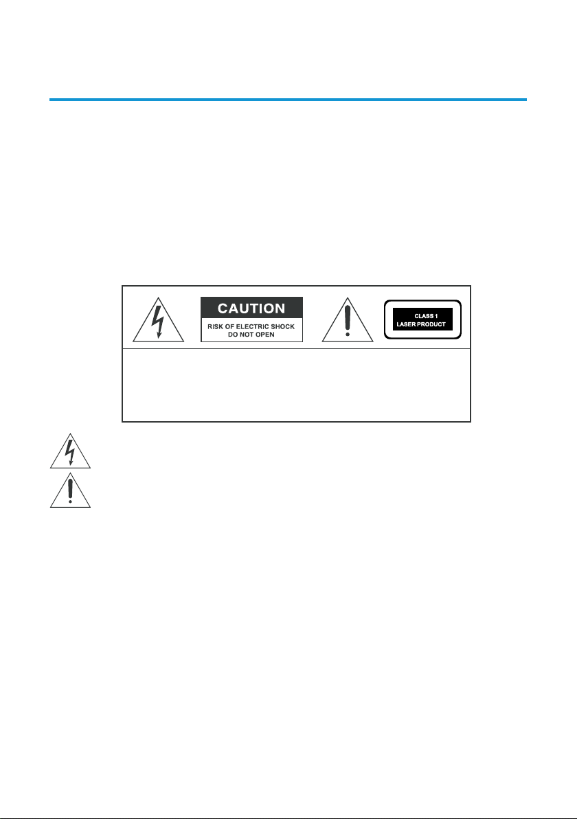
IMPORTANT SAFETY INSTRUCTIONS
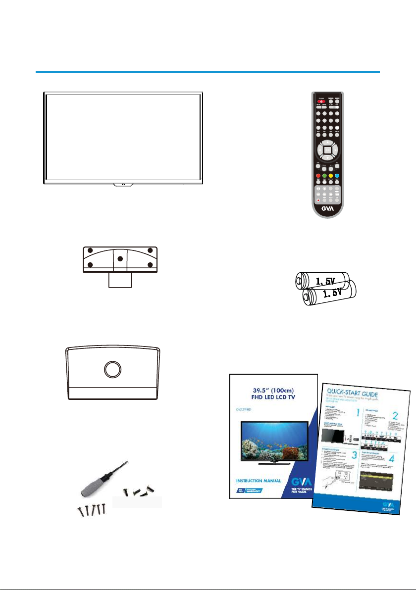
Read this manual thoroughly before rst use and keep it in a safe place for future reference,
along with the warranty card, purchase receipt and carton. The safety precautions enclosed
herein reduce the risk of re, electric shock and injury when correctly adhered to.
Usage conditions and restrictions
To prevent any injuries, the following safety precautions should be observed in the
installation, use, servicing and maintenance of equipment. Before operating this equipment,
please read this manual completely, and keep it nearby for future reference.
• Take notice of all the warnings.
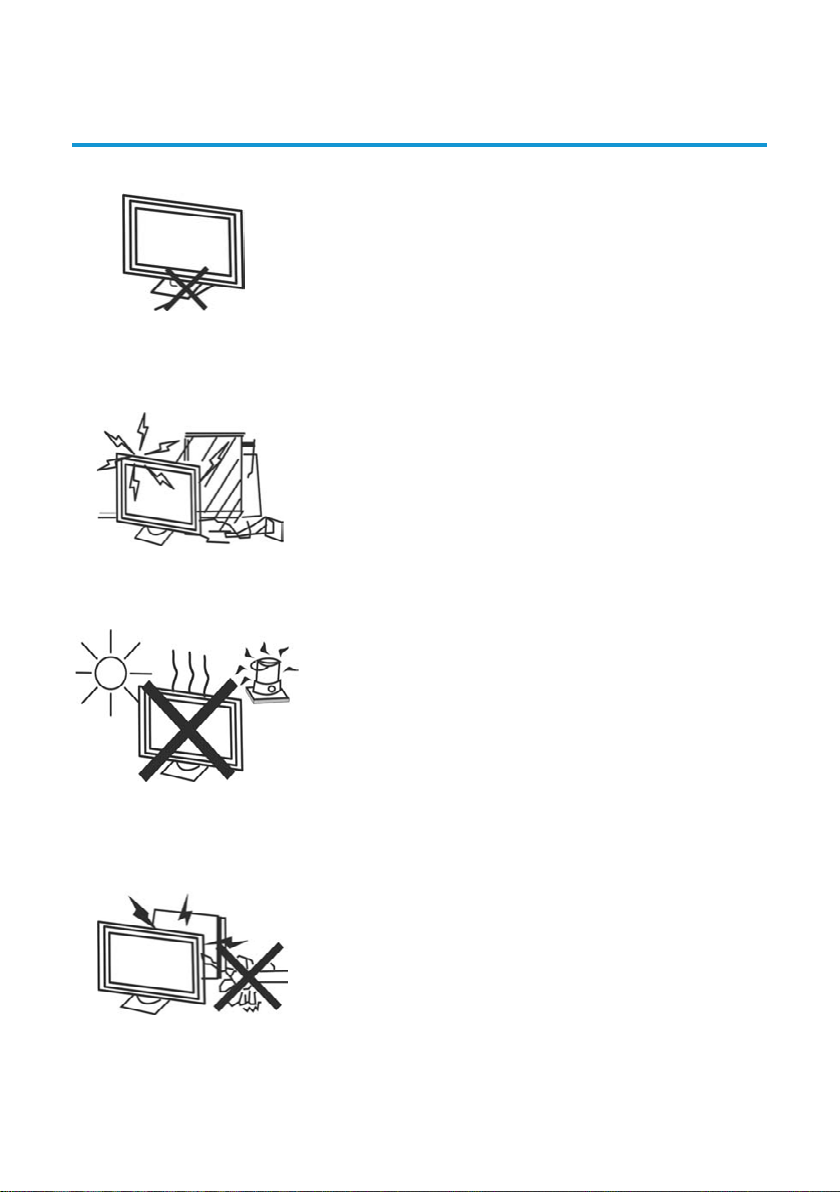
• Do not use this TV near water.
• Clean only with a dry cloth.
• Do not block any of the ventilation openings.
• Install in accordance with the manufacturer’s instructions.
• Do not install near any heat sources such as radiators, heat registers, stoves, or other
TV’s (including ampliers) that produce heat.
• Do not alter the grounding type plug provided with the TV. A grounding type plug
has two blades and a third grounding prong. The third prong is provided for your
safety. When the provided plug does not t into your outlet, consult an electrician for
replacement of the obsolete outlet.
• Protect the power cord from being walked on or pinched particularly at plugs,
convenience receptacles, and the point where they exit from the TV.
• Only use the attachments/accessories specied by the manufacturer.
• Use only with a cart, stand, tripod, bracket, or table specied by the manufacturer, or
sold with the TV.
• Unplug this TV during lightning storms or when unused for long periods of time.
• The appliance is not intended for use by persons (including children) with reduced
physical, sensory or mental capabilities, or lack of experience and knowledge, unless
they have been given supervision or instruction concerning use of the appliance by a
person responsible for their safety.
• Young children should be supervised to ensure they do not play with the appliance.
• Refer all servicing to qualied service personnel. Servicing is required when the TV has
been damaged in any way, such as power supply cord or plug is damaged, liquid has
been spilt or objects have fallen into the TV, the TV has been exposed to rain or moisture,
does not operate normally, or has been dropped.
• If the supply cord is damaged, it must be replaced by the manufacturer, its service agent
or similarly qualied persons in order to avoid a hazard.
NOTE: The TV must not be exposed to dripping or splashing and no objects lled with
liquids, such as vases, should be placed on the TV.