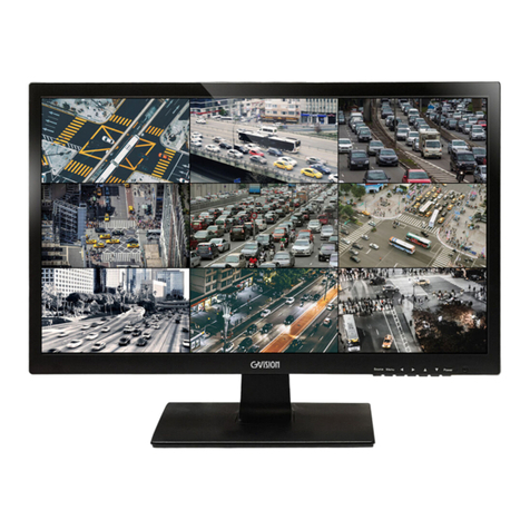
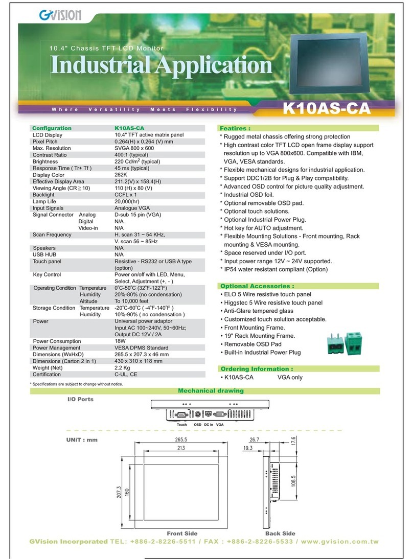
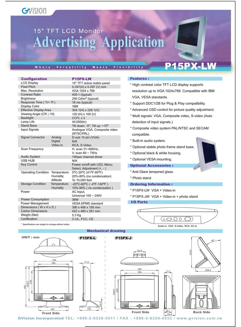
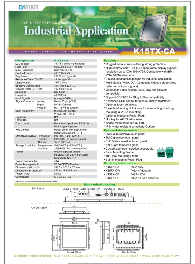
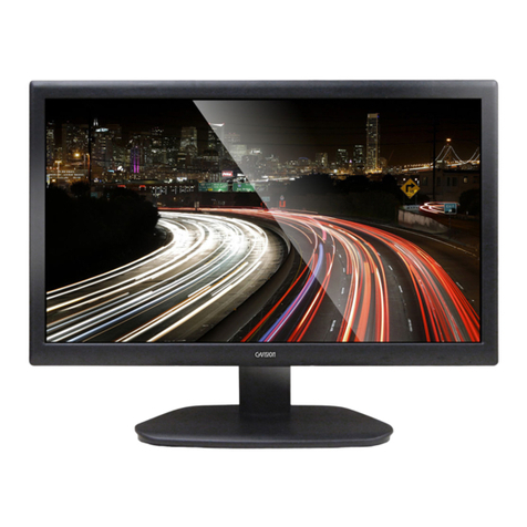
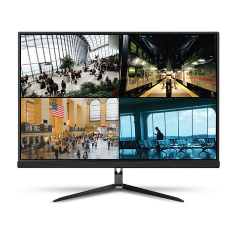
GVision VW55CD-OM-40003 User manual

VW55CD-OM-
40003
USER’S MANUAL
3.5MM BEZEL /55-INCH VIDEO WALL MONITOR
GVISION USA, INC
30398 Esperanza, Rancho Santa Margarita CA 92688 / 949.586.3338 / info@gvision-usa.com
WWW.GVISION-USA.COM

WWW.GVISION-USA.COM
30398 Esperanza Rancho Santa Margarita CA 92688 / Tel. 949-586-3338 / Fax. 949-272-4594 / Email. info@gvision-usa.com
2
Important Information
Care and Cleaning
WARNING
TO PREVENT FIRE OR SHOCK HAZARDS, DO NOT EXPOSE THIS UNIT TO RAIN OR MOISTURE. ALSO, DO NOT USE THIS
UNIT’S POLARIZED PLUG WITH AN EXTENSION CORD RECEPTACLE OR OTHER OUTLETS UNLESS THE PRONGS CAN BE
FULLY INSERTED.
REFRAIN FROM OPENING THE CABINET AS THERE ARE HIGH VOLTAGE COMPONENTS INSIDE. REFER SERVICING TO
QUALIFIED SERVICE PERSONNEL.
CAUTION
TO REDUCE THE RISK OF ELECTRIC SHOCK, MAKE SURE POWER CORD IS UNPLUGGED FROM WALL SOCKET. TO FULLY
DISENGAGE THE POWER TO THE UNIT, PLEASE DISCONNECT THE POWER CORD FROM THE AC OUTLET. DO NOT
REMOVE COVER (OR BACK). NO USER SERVICEABLE PARTS INSIDE. REFER SERVICING TO QUALIFIED SERVICE
PERSONNEL.
This symbol warns user that uninsulated voltage within the unit may have sufficient magnitude to cause electric shock.
Therefore, it is dangerous to make any kind of contact with any part inside this unit.
This symbol alerts the user that important literature concerning the operation and maintenance of this unit has been included.
Therefore, it should be read carefully in order to avoid any problems.
CAUTION: Please use the power cord provided with this display in accordance with the table below. If a power cord is not supplied with
this equipment, please contact GVISION. For all other cases, please use the power cord with the plug style that matches the power
socket where the monitor is located. The compatible power cord corresponds to the AC voltage of the power outlet and has been
approved by, and complies with, the safety standards in the country of purchase.
*When operating this monitor with its AC 125-240V power supply, use a power supply cord that matches the power supply voltage of
the AC power outlet being used.
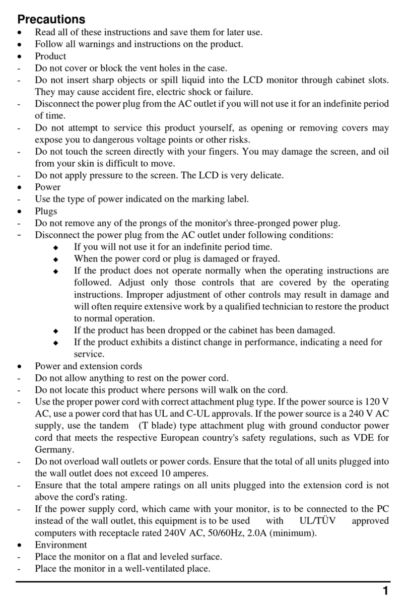
•Always unplug your monitor from the wall outlet before cleaning. Clean the LCD monitor surface with a lint-free, non-abrasive
cloth. Avoid using any liquid, aerosol or glass cleaners.
•Slots and openings on the back or top of the cabinet are for ventilation. They must not be blocked or covered. Your monitor
should never be placed near or over a radiator or heat source, or in a built-in installation unless proper ventilation is provided.
•Never push objects or spill liquid of any kind into this product.

WWW.GVISION-USA.COM
30398 Esperanza Rancho Santa Margarita CA 92688 / Tel. 949-586-3338 / Fax. 949-272-4594 / Email. info@gvision-usa.com
3
Safety Precautions / Maintenance
Do not use this apparatus near water.
Clean only with dry cloth.
Do not block any ventilation openings. Install in
accordance with the manufacturer’s instructions.
Do not install near any heat sources such as radiators,
heat registers, stoves, or other apparatus (including
amplifiers) that produce heat.
Do not defeat the safety purpose of the polarized or
grounding-type plug. A polarized plug has two blades
with one wider than the other. A grounding type plug
has two blades and a third grounding prong. The wide
blade or the third prong are provided for your safety. If
the provided plug does not fit into your outlet, consult an
electrician for replacement of the obsolete outlet.
Protect the power cord from being walked on or pinched
particularly at plugs, convenience receptacles, and the
point where they exit from the apparatus.
Only use attachments/accessories specified by the
manufacturer.
Use only with the cart, stand, tripod, bracket, or table
specified by the manufacturer, or sold with the
apparatus. When a cart is used, use caution when
moving the monitor combination to avoid injury from tip-
over.
Unplug the monitor during lightning storms or when
unused for long periods of time.
Refer all servicing to qualified service personnel.
Servicing is required when the apparatus has been
damaged in any way, such as power-supply cord or
plug is damaged, liquid has been spilled or objects have
fallen into the apparatus, the monitor has been exposed
to rain or moisture, does not operate normally, or has
been dropped.
Do not press strongly upon the panel with a hand or a
sharp object such as a nail, pencil, or pen, or make a
scratch on it.
Do not stick metal objects or any other conductive
material into the power cord. Do not touch the end of
the power cord while it is plugged in.
Keep the packing anti-moisture material or vinyl
packing out of the reach of children. Anti-moisture
material is harmful if swallowed. If swallowed, induce
vomiting and go to the nearest hospital. Additionally,
vinyl packing can cause suffocation. Keep it out of the
reach of children.
Concerning the Power Cord (Can differ by country):
Check the specification page of this owner’s manual to
be certain concerning current requirements. Do not
connect too many devices to the same AC power outlet
as this could result in fire or electric shock. Do not
overload wall outlets. Overloaded wall outlets, loose or
damaged wall outlets, extension cords, frayed power
cords, or damaged or cracked wire insulation are
dangerous. Any of these conditions could result in
electric shock or fire. Periodically examine the cord of
your device, and if its appearance indicates damage or
deterioration, unplug it, discontinue use of the device,
and have the cord replaced with an exact replacement
part by an authorized servicer. Protect the power cord
from physical or mechanical abuse, such as being
twisted, kinked, pinched, closed in a door, or walked
upon. Pay particular attention to plugs, wall outlets, and
the point where the cord exits the device. Do not move
the monitor with the power cord plugged in. Do not use
a damaged or loose power cord. Be sure do grasp the
plug when unplugging the power cord. Do not pull on
the power cord to unplug the monitor.
To reduce the risk of fire or electrical shock, do not
expose this product to rain, moisture or other liquids. Do
not touch the screen with wet hands. Do not install this
product near flammable objects such as gasoline or
candles, or expose the TV to direct air conditioning.
Do not use high voltage electrical equipment near the
TV (e.g., a bug zapper). This may result in product
malfunction.
Do not expose to dripping or splashing and do not place
objects filled with liquids, such as vases, cups, etc. on
or over the apparatus (e.g., on shelves above the unit).
Do not attempt to modify this product in any way without
written authorization from GVISION. Unauthorized
modification could void the user’s authority to operate
this product.
Moving: Make sure the product is turned off, unplugged,
and all cables have been removed. Do not press or put
stress on the front panel of the monitor screen.
If you smell smoke or other odors coming from the
monitor screen, unplug the power cord and contact an
authorized service center.
If water or another substance enters the product (like an
AC adapter, power cord, or display unit), disconnect the
power cord and contact the service center immediately.
Otherwise, this may result in fire or electric shock.
WWW.GVISION-USA.COM
30398 Esperanza Rancho Santa Margarita CA 92688 / Tel. 949-586-3338 / Fax. 949-272-4594 / Email. info@gvision-usa.com
4
Table of Contents
1. Controllers & Settings……………………………………………………………………………………………………5
1.1 Monitor Interface………………………………………………………………………………………………….5
1.2 Remote Control……………………………………………………………………………………………………6
1.2.1 IR Receiver………………………………………………………………………………………………..6
1.2.2 Software Address Setting…………………………………………………………………………...…7
2. Color Balance Adjustment………………………………………………………………………………………..….10
2.1 Preparation……………………………………………………………………………………………………..…10
2.2 Adjustment…………………………………………………………………………………………………...…...12
3. Driver Board…………………………………………………………………………………..…………...…...............15
3.1 Features…………………………………………………………………………………………………………....15
3.2 Driver-Board Overview…………………………………………………………………………………...……..16
3.3 Main-Board Description………………………………………………………………………………………...17
3.3.1 PCB Dimension………...……………………………………………………………………………..…17
3.3.2 Mechanical Dimension…………………………………………………………………………………17
3.4 I/O Description.…………………………………………………………………………………………...………17
3.5 Performing Index…………………………………………………………………………………………………21
3.6 Software Upgrade……………………………………………………………………………………………..…21
4. Power Board……………………………………………………………………………………………………………..22
4.1 Isolation……………………………………………………………………………………………………………25
4.2 Safety……………………………………………………………………………………………………………….25
4.3 EMC……………………………………………………………………………………………………………..….25
4.4 Environmental Requirement…………………………………………………………………………………...26
4.5 Dimension…………………………………………………………………………………………………………26
4.6 Weight……………………………………………………………………………………………………………...26
4.7 Pin Connection…………………………………………………………………………………………………...27
4.8 Power Supply Mounting………………………………………………………………………………………...28
5. Specification…………………………………………………………………………………………………………..29
6. Mechanical Drawing………………………………………………………………………………………………….30

WWW.GVISION-USA.COM
30398 Esperanza Rancho Santa Margarita CA 92688 / Tel. 949-586-3338 / Fax. 949-272-4594 / Email. info@gvision-usa.com
5
INTERFACES INSTRUCTION
1 DVI IN DVI Input Source
2 HDMI IN 1 HDMI 1 Input Source
3 HDMI IN 2 HDMI 2 Input Source
4 DP IN DisplayPort (DP) Input Source
5 DP OUT DisplayPort (DP) Output Source
6 USB IN Software Update
7 RS232 IN Control the Screen via RS232 Protocol Input
8 RS232 OUT Control the Screen via RS232 Protocol Output
GVision’s 3.5mm Ultra Narrow Bezel Video Wall monitors designed for 24/7 365 mission-critical operations.
GVision provides a complete Video Wall Solutions.
1Controllers & Settings
1.1 Monitor Interface

WWW.GVISION-USA.COM
30398 Esperanza Rancho Santa Margarita CA 92688 / Tel. 949-586-3338 / Fax. 949-272-4594 / Email. info@gvision-usa.com
6
FUNCTIONS
1 Power Off
2 Power On
3 ID: Software address setting
4 Source: Change media source
5 Menu: Press to access the menu
6 Up: Press to move up
7 Left: Press to move left
8 Right: Press to move right
9 Down: Press to move down
10 Enter: Press to enter
11 Exit: Press to exit the menu
1.2 Remote Control
1.2.1 IR Receiver
Plug the IR receiver in the RS232 (RJ45 Shape) port.

WWW.GVISION-USA.COM
30398 Esperanza Rancho Santa Margarita CA 92688 / Tel. 949-586-3338 / Fax. 949-272-4594 / Email. info@gvision-usa.com
7
1.2.2 Software Address Setting
Press the MENU button from the
remote controller to display
following image (Figure 1.1).
Figure 1.1
Figure 1.2
Press UP/DOWN to move and
select VIDEO WALL icon, press
ENTER. (Figure 1.2)
Press ENTER again to set the ID.

WWW.GVISION-USA.COM
30398 Esperanza Rancho Santa Margarita CA 92688 / Tel. 949-586-3338 / Fax. 949-272-4594 / Email. info@gvision-usa.com
8
Figure 1.3
The ID is randomly generated, if
any duplicated ID found on
screens, press the ENTER again
to re-generate ID until all IDs are
independent. (Figure 1.3)
Fill in the numbers according to
the generated ID, then press EXIT
to return.
.
Figure 1.4
Press UP/DOWN to navigate and
set parameters item by item. (The
following takes 3Χ3 video wall as
an example). (Figure 1.4)
The [Row Start] item and
[Column Start] item
represent the software
address of the top-left screen
in the wall matrix.
The [Row End] item and
[Column End] item
represent the software
address of the bottom-right
screen in the wall matrix.

WWW.GVISION-USA.COM
30398 Esperanza Rancho Santa Margarita CA 92688 / Tel. 949-586-3338 / Fax. 949-272-4594 / Email. info@gvision-usa.com
9
Row Start 1 Row End 1
Column Start 3 Column End 3
Row Total 3 Column Total 3
Example of 3x3 Video Wall Configuration.
Move to [Video Wall Enable], select [On] to start splicing, select [Off] to display
independently.

WWW.GVISION-USA.COM
30398 Esperanza Rancho Santa Margarita CA 92688 / Tel. 949-586-3338 / Fax. 949-272-4594 / Email. info@gvision-usa.com
10
2.1 Preparation
2Color Balance Adjustment
Enter the factory menu through MENU+1234 on the remote control to check the version information and the
production date of the software.
Note: Try not to use different software which may lead to problems due to customized effects.
Make a pure white and a pure
black picture (red, green and blue
are both 255, the following picture
is the setting method of the
drawing tool in the WIN10 system,
other systems are similar), If it is a
scene with a lot of static files, you
can create pictures similar to pure
red, pure green and pure blue, or
use a small tool to generate it
yourself, in following test will be
used.
It is recommended to use the host computer for debugging work, which is convenient and
quick to operate.

WWW.GVISION-USA.COM
30398 Esperanza Rancho Santa Margarita CA 92688 / Tel. 949-586-3338 / Fax. 949-272-4594 / Email. info@gvision-usa.com
11
Use the host computer control:
after Unicom host computer, first
perform the overall reset action,
the password is “cjfw”, Ensure
that the software is in the default
factory state.
NOTE: To avoid the reset action during the customer is in use, do not send this password to the
customer.
After the screen is reset, set the ID address of each screen through the host computer or
remote control.
NOTE: Press the ID key on the remote control to call up the setting interface, and the host
computer needs to enter the super user interface; Part of the parameters and parameter
positions needed to adjust the screen:
Some parameters and parameter positions needed to adjust the screen.
PC software:
Open the image adjustment interface, and the adjustment is mainly based on "brightness",
"red gain", "green gain", "blue gain" and "saturation". When adjusting the screen, you need
to select the corresponding screen in the main frame. Then adjust the parameters in
"Image Adjustment".
Please do not do any operation on the backlight brightness.

WWW.GVISION-USA.COM
30398 Esperanza Rancho Santa Margarita CA 92688 / Tel. 949-586-3338 / Fax. 949-272-4594 / Email. info@gvision-usa.com
12
Use the remote control to press
the MENU key button to access
the “Color” menu.
The parameters are mainly red
gain, green gain and blue gain in
white balance.
2.2 Adjustment
Figure 2.1
Play the
black picture in full
screen, as shown in figure 2.1,
and observe whether the picture
has whitening or uneven the
brightness.
•Screen whitening: Reduce the
brightness value of a single
screen.
•The black field of the screen
is uneven
: This situation is
caused by the unevenness of
the light guide plate. This state
is not avoided. It is necessary to
increase the brightness value to
make the screen white as much
as possible, Adjust the value
within 10 unit values.

WWW.GVISION-USA.COM
30398 Esperanza Rancho Santa Margarita CA 92688 / Tel. 949-586-3338 / Fax. 949-272-4594 / Email. info@gvision-usa.com
13
Figure 2.2
After the black picture is adjusted,
the created pure white picture will
be played in full screen at this
time.
Stand in front of the screen to
observe the splicing and select
one of the most gray and dark
screens, as shown in the figure
2.2.
Taking the darker screen as the benchmark, adjust the brightness and grayscale of other
screens to a similar level to the dark screen.
Specific method: Reduce the brightness of the lower screen of the white screen by reducing
the red, green and blue gains in the color temperature of a single screen. For example, the
above picture should be based on the first screen in the upper left corner, and the surrounding
screens should reduce the red, green and blue gains one by one to achieve dark degree of
consistency.
Note: Try not to operate by reducing the brightness. First, the brightness has changed after
adjusting the black point, and second, the brightness change will also cause a large difference in
color temperature.
The solution to the color deviation between the screens under the white screen:
•Picture is reddish: reduce the "red gain" or increase ("green gain" and "blue gain")
•Picture is greenish: Decrease "Green Gain" or increase ("Red Gain" and "Blue Gain")
•Picture is bluish: Decrease "Blue Gain" or increase ("Red Gain" and "Green Gain")
•Picture is yellowish: increase "Blue Gain" or decrease ("Red Gain" and "Green Gain")
•Picture is purple: increase the "green gain" or decrease ("red gain" and "blue gain")
•Picture is too blue: increase the "red gain" or decrease ("blue gain" and "green gain")
Note: Changing the "Blue Gain" has a great impact on the brightness of the picture, try to minimize
the changes to the "Blue Gain"

WWW.GVISION-USA.COM
30398 Esperanza Rancho Santa Margarita CA 92688 / Tel. 949-586-3338 / Fax. 949-272-4594 / Email. info@gvision-usa.com
14
Figure 2.3
In response to the problem of
inconsistent colors in the solid color
screen raised by the customer, first
confirm that the white screen has
been debugged, and then refer to
the following method, the effect is
shown in the figure 2.3
•The difference in color shades is slight: it can be improved by increasing the "saturation" of
the screen with slightly lighter colors.
•Large difference in color shades: it can be improved by reducing the "saturation" of the screen
with higher color density.
•The problem of color cast, for example, some screens are watery red or purple under the red
screen, and some screens are green or blue under the yellow screen. At this time, please
make sure that the colors of pure red, pure green and pure blue are not too different; if the
color cast problem cannot be reduced by adjustment, please try to reduce the "saturation" to
improve such problems.
Note: Reducing the saturation will result in a lighter color, so the one with the closest visual effect
is the best.

WWW.GVISION-USA.COM
30398 Esperanza Rancho Santa Margarita CA 92688 / Tel. 949-586-3338 / Fax. 949-272-4594 / Email. info@gvision-usa.com
15
Support dual-channel 10bit LVDS output, output resolution 1920*1080@60Hz.
Support quad-way signal source picture-splice-picture function, support dual-way signal
source picture-in-picture function.
Support 90 degree, 180 degree, and 270 degree rotation of the screen, and the highest
resolution of the rotation function supports 1920*1080@60hz.
Support 1080P signal three-line synchronous display.
Support input signal:
•1 Χ DVI;
•3 Χ HDMI-in (the highest resolution supports 4096x2160@30Hz)
•1 Χ DP-in (the highest resolution supports 3840*2160@60Hz)
•1 Χ USB
•1 Χ RS232-in (RJ45 Shape)
Output signal:
•1 Χ DP-out
•2 Χ RS232-out (RJ45 Shape)
Support DP daisy chain (the highest resolution supports 3840*2160@60Hz).
Using the latest LVDS driver chip, the peripheral circuit is simpler and the power
consumption is lower.
With an automatic temperature control system, work is stable.
With USB upgrade function, easy maintenance and assembly.
Efficient 3D comb filter image processing engine, the output image is clearer and more
realistic.
Complete hardware design without OS.
Multi-CANBUS parallel processing, powerful processing capability.
Work 24/7.
Support remote control to operate all splicing functions.
No risk of virus infection, good safety.
3Driver Board
M292W is a TFT-LCD driver board specially designed for displays. It adopts a highly integrated LVDS LCD screen
driver chip, which enables it to have a smaller PCB size, support abundant signal source input, and high-quality
1080P image output.
3.1 Features

WWW.GVISION-USA.COM
30398 Esperanza Rancho Santa Margarita CA 92688 / Tel. 949-586-3338 / Fax. 949-272-4594 / Email. info@gvision-usa.com
16
I/O Port Overview
1 (CN38) DVI Input 10 (J11) Fan Connector 1
2 (CN4) HDMI Input 1 11 (J10) Fan Connector 2
3 (CN6) HDMI Input 2 12 (CN34) OSD Connector
4 (CN2) DP Input 13 (J3) UART Connector
5 (CN28) DP Output 14 (CN25) I2C & ADC Connector
6 (CN31) USB (Upgrade) 15 (CN33) Power Input
7 (J7) RS232 Input 16 (CN36) Backlight Connector
8 (CN32) 2 Χ RS232 Output 17 (CN39) Screen Cable Connector
9 (J12) External RTC 18 (CN37) Internal HDMI Input
3.2 Driver-Board Overview

WWW.GVISION-USA.COM
30398 Esperanza Rancho Santa Margarita CA 92688 / Tel. 949-586-3338 / Fax. 949-272-4594 / Email. info@gvision-usa.com
17
PCB Dimension: 1.6mm (H) x 201mm (L) x 122mm (W)
3.3 Main-Board Description
3.3.1 PCB Dimension
3.3.2 Mechanical Dimension

WWW.GVISION-USA.COM
30398 Esperanza Rancho Santa Margarita CA 92688 / Tel. 949-586-3338 / Fax. 949-272-4594 / Email. info@gvision-usa.com
18
J12 (2PIN/2.54mm): External RTC
NO
SYMBOL
DESCRIPTION
1
NTC
Temperature Sensor Signal Input
2
GND
Ground
J10, J11 (3PIN/2.54mm): Fan Connector
NO
SYMBOL
DESCRIPTION
1
FAN
12V Fan Power
2
NC
NC
3
GND
Ground
CN34 (14Pin/2.0mm): OSD Connector
NO
SYMBOL
DESCRIPTION
1
POWER
Power On/Off
2
DOWN
Down
3
UP
Up
4
ENTER
Confirm
5
MENU
Menu
6
SOURCE
Signal Source Switch
7
AUTO
Automatic
8
GND
Ground
9
LED-G
Green LED Light
10
LED-R
Red LED Light
11
K8
K8 Key
12
GND
Ground
13
IR-IN
Infrared Reception
14
5V
5VDC Power
J3 (4Pin/2.0mm): UART Connector
NO
SYMBOL
DESCRIPTION
1
3.3V
3.3V Stand-by Power
2
GND
Ground
3
RX
Reception
4
TX
Transmission
3.4 I/O Description

WWW.GVISION-USA.COM
30398 Esperanza Rancho Santa Margarita CA 92688 / Tel. 949-586-3338 / Fax. 949-272-4594 / Email. info@gvision-usa.com
19
CN25 (5Pin/2.0mm):I2C & ADC Connector
NO
SYMBOL
DESCRIPTION
1
ADC
Analog-Digital Conversion
2
GND
Ground
3
SDA
Data
4
SCL
Clock
5
3.3V
3.3V Stand-by Power
CN33 (10PIN /2.54mm): Power Input
NO
SYMBOL
DESCRIPTION
1
STB
Power Control Pin
2
GND
Ground
3
GND
Ground
4
5VS
5V Stand-by Power
5
5V
5V Controlled DC Power Supply
6
5V
5V Controlled DC Power Supply
7
GND
Ground
8
GND
Ground
9
12V
12V Controlled DC Power Supply
10
12V
12V Controlled DC Power Supply
CN36 (6Pin/2.0mm): Backlight Connector
NO
SYMBOL
DESCRIPTION
1
GND
Ground
2
GND
Ground
3
ADJ
Brightness Adjustment
4
BL
Backlight On/Off Pin
5
12V
12V DC Power Output
6
12V
12V DC Power Output

WWW.GVISION-USA.COM
30398 Esperanza Rancho Santa Margarita CA 92688 / Tel. 949-586-3338 / Fax. 949-272-4594 / Email. info@gvision-usa.com
20
CN39 (2X18_2.0mm): Screen Cable Connector
NO
SYMBOL
DESCRIPTION
1
VLCD
Power Out
2
VLCD
Power Out
3
VLCD
Power Out
4
SEL
Data Format Selection
5
GND
Ground
6
GND
Ground
7
GND
Ground
8
GND
Ground
9
4-
Data Channel 4-
10
4+
Data Channel 4+
11
3-
Data Channel 3-
12
3+
Data Channel 3+
13
C-
Clock Channel C-
14
C+
Clock Channel C+
15
2-
Data Channel 2-
16
2+
Data Channel 2+
17
1-
Data Channel 1-
18
1+
Data Channel 1+
19
0-
Data Channel 0-
20
0+
Data Channel 0+
21
GND
Ground
22
GND
Ground
23
04-
Data Channel 04-
24
04+
Data Channel 04+
25
03-
Data Channel 03-
26
03+
Data Channel 03+
27
0C-
Clock Channel 0C-
28
0C+
Clock Channel 0C+
29
02-
Data Channel 02-
30
02+
Data Channel 02+
31
01-
Data Channel 01-
32
01+
Data Channel 01+
33
00-
Data Channel 00-
34
00+
Data Channel 00+
35
GND
Ground
36
GND
Ground
Table of contents
Other GVision Monitor manuals

GVision
GVision P17PH-L User manual

GVision
GVision K12TS-C User manual

GVision
GVision P10PS-J User manual

GVision
GVision K08AS-F User manual

GVision
GVision P17BH-D User manual

GVision
GVision I43ZI-OC-45P0 User manual

GVision
GVision P17PH-L User manual

GVision
GVision P10PS-JW User manual

GVision
GVision L5PX Series User manual

GVision
GVision P12AS-L User manual

GVision
GVision K15TX-C User manual

GVision
GVision K12TS-C User manual

GVision
GVision K10AS-CA User manual

GVision
GVision K19BH-F User manual

GVision
GVision F17AH-D User manual

GVision
GVision K17TH-C User manual

GVision
GVision P12ES-L User manual

GVision
GVision C19BD-A6-4000 User manual

GVision
GVision P15PX-L User manual

GVision
GVision P17BH-AA User manual