H.C Duke & Son Arby's Electro Freeze Compact Series Manual

H. C. Duke & Son, LLC P/N 185260 June 2017 Printed in U.S.A.
COMPACT SERIES
SHAKE FREEZER
Model CS704
185260 - 6/17
OPERATOR’S MANUAL
with Replacement Parts List


Operator’s Manual
for the
Electro Freeze Model CS704
Compact Series Flavor Injected
Shake Freezer
All contents © Copyright 2017 H.C. Duke & Son, LLC, 2116 Eighth Avenue, East Moline, Illinois 61244
i
ELECTRO FREEZE Shake Model CS704
ii
SAFETY FIRST!
3. Follow Safety Instructions ....
Read and understand all safety messages in this manual.
Read and understand the decal safety messages on your
freezer. Take notice of the location of all decals on the freezer
and keep the safety decals in good condition. Check them
periodically and replace missing, damaged or illegible safety
decals. The safety decals must remain in place and legible
for the life of the freezer. If you need new decals, use the
information and illustrations on pages v and vi of this manual to
identify the decal and call or write to H.C. Duke & Son, LLC. or
local Electro Freeze distributor.
DO NOT attempt to operate the soft serve freezer until you
read and understand all safety messages and the operating
instructions in this manual.
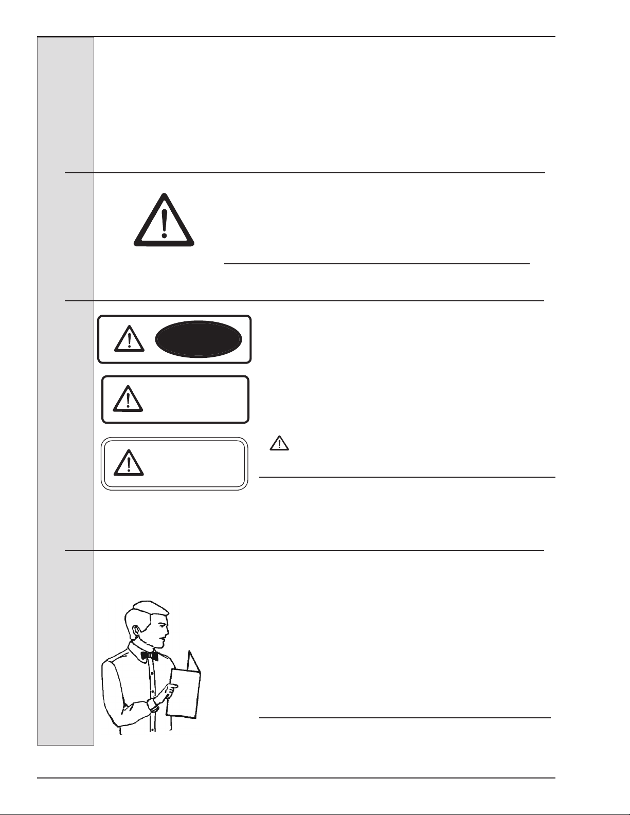
DANGER
The signal words — DANGER, WARNING and
CAUTION — are used with the safety alert symbol
(DANGER decals on the freezer may or may not have the
safety alert symbol, but the message is the same). Decals
with the words DANGER, WARNING or CAUTION appear
on the freezer. DANGER identies the most serious
hazard. Decals with the words DANGER or WARNING
are typically near specic hazards on the freezer. General
precautions are listed on CAUTION safety decals. In this
manual, CAUTION messages with the safety alert symbol
call attention to safety messages.
1. Recognize Safety Information ....Look for this
safety alert symbol throughout this manual.
When you see this symbol on your freezer or in this manual, be
alert to the potential for personal injury. Follow recommended
precautions and safe operating practices.
2. Understand Signal Words ....
Follow these four steps to safety ....
WARNING
CAUTION

ELECTRO FREEZE Shake Model CS704
SAFETY FIRST!
iii
Trained person (or Operator): A person who has been trained in the basic operation of
the freezer. This person is knowledgeable in the operation of machine startup, stopping,
lling, and basic cleaning, disassembly, washing, and sanitation of the freezer.
Freezer Technician: A person who has been trained by a factory representative, or
an experienced and qualied service person, to perform more complicated operations
such as freezer installation, maintenance repairs, component replacement , is aware of
hazards associated with electricity, moving parts, and takes necessary steps to protect
against injury to themselves and other people.
4. Definitions ....
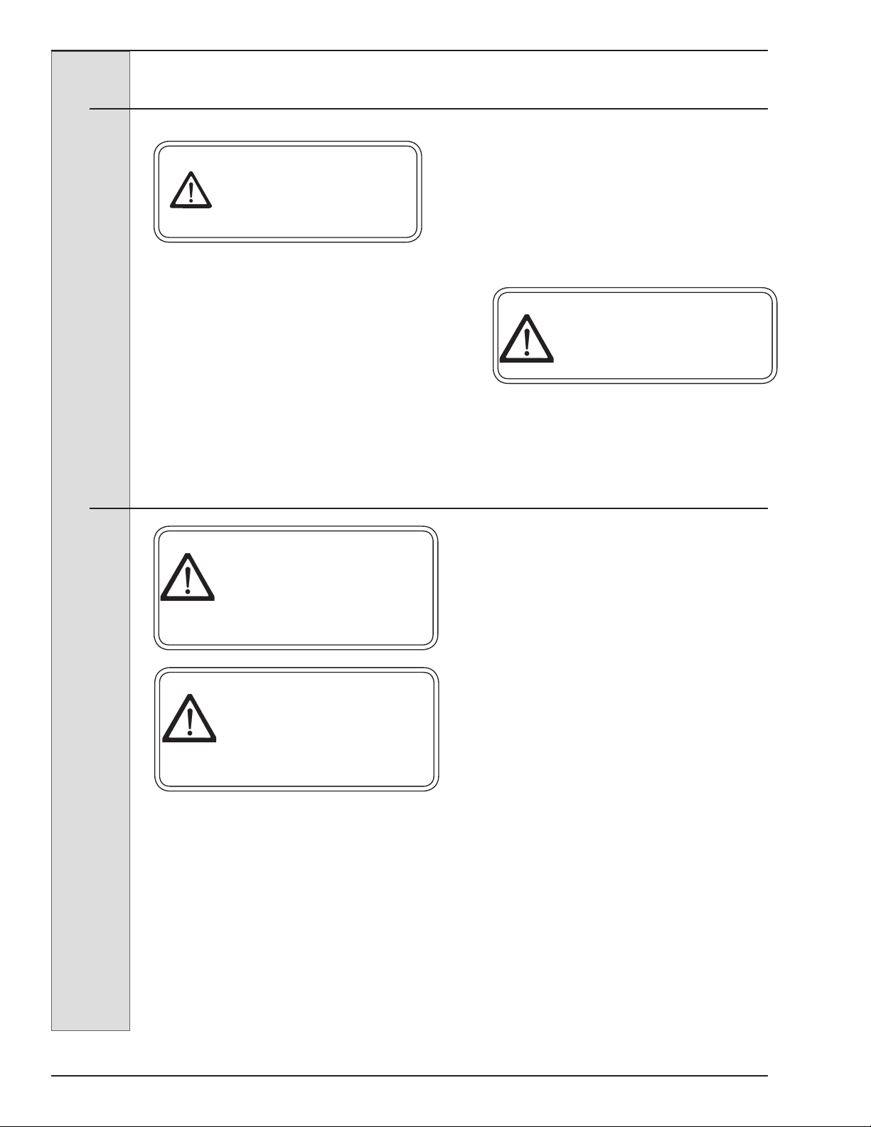
5. Operate Safely ....
DO NOT allow untrained personnel to maintain or
service this freezer. Failure to follow this instruction
may result in severe personal injury. DO NOT operate
the freezer until all service and access covers are
secured with screws. DO NOT attempt to repair
the freezer until the main power supply has been
disconnected. Some freezers have more than one
disconnect switch. Contact your authorized service
representative for original equipment parts.
6. Caution ....
• This Freezer is to be operated by trained persons. The Dispense
feature, if used by public in self-serve applications, shall be monitored
by trained persons able to assist people with physical, sensory or mental
impaired capabilities.
• Children should not be allowed to play around this equipment.
• Do not store explosive substances such as aerosol cans with a ammable propellant
in freezer.
• This appliance is not designed for outdoor weather conditions and shall not be
exposed to rain.
• Do not wash machine with power sprayer. Do not install machine next to a power
sprayer where splash of freezer can occur.
• Machine is designed for use in areas of normal atmosphere. It is not to be used in
areas subject to explosion-proof standards.
IMPORTANT: Store Managers,owners, and supervisors must be aware of staff
capabilities and that they do not perform freezer operations outside their level of
knowledge or responsibility.

ELECTRO FREEZE Shake Model CS704
iv
Safety Decal Locations
Do not attempt to operate the freezer
until all safety precautions and operating
instructions in this manual are read and
understood.
Take notice of all warning, caution,
instruction and information decals (or
labels) on the freezer as shown in the
gure on the following page. The labels
have been put there to help maintain a
safe working environment.
The labels have been designed to
withstand washing and cleaning. All
labels must remain legible for the life of
the freezer. Check labels periodically
to be sure they can be recognized as
warning labels.
If it is necessary to replace any label,
please contact your local authorized
Electro Freeze Distributor or H. C. Duke
& Son, LLC. When ready to order you will
need to determine the (1) part number,
(2) type of label, (3) location of label, and
(4) quantity required, and include a return
shipping address.
You may contact your local authorized
Electro Freeze Distributor, as follows:
Name:
Address:
Phone:
or — for factory service assistance —
contact H. C. Duke & Son, LLC. Electro
Freeze Service Department by phone or
FAX:
Phone: 309-755-4553
800-755-4545
FAX: 309-755-9858
(The decals on the next page are num-
bered 1 and 2. Those numbers corre-
spond to the numbers in the table below.
The table provides the part number,
description, and quantity for each decal.)
No. Part No. Description (Qty)
1 HC165126 Decal — Panel Removal Warning (3)
2 HC165025 Decal — Beater Warning (1)

ELECTRO FREEZE Shake Model CS704
Safety Decal Locations
v
1 P/N HC165126
2 P/N HC165025

ELECTRO FREEZE Shake Model CS704
Table of Contents
SECTION DESCRIPTION PAGE
SAFETY ...........................................................................................ii
SAFETY DECALS LOCATIONS............................................iv
PART I
1. INTRODUCTION .............................................................................1
2. NOTE TO INSTALLER ...................................................................1
2.1. Uncrating and Inspection ................................................................2
2.2. Installation ......................................................................................2
2.3 Electrical Connections ...................................................................3
3. SPECIFICATIONS ...........................................................................3
3.1 Particulars.......................................................................................3
3.2 Data Plate........................................................................................4
3.3 Reference Information .....................................................................4
3.4 Installation Date ..............................................................................4
3.5 Dimensions......................................................................................5
4. PART NAMES AND FUNCTIONS .............................................6
5. OPERATOR CONTROLS & INDICATORS .................. 10
5.1 Rinse Switch .................................................................................11
5.2 Spinner Motor Fuse .......................................................................11
5.3 Lexible Spinner Shaft.....................................................................11
5.4 Reset -Circuit Breaker ...................................................................11
5.5 Selector Switch .............................................................................11
5.6 Prime / Calibrate............................................................................12
5.7 Flavor Selection Buttons................................................................12
5.8 Indicator Light “ADD MIX” .............................................................12
5.9 Mix Float........................................................................................12
6. DISASSEMBLY AND CLEANING ...........................................13
6.1 Accessories ..................................................................................13
6.2 Disassembly Instructions...............................................................14
6.3 Cleaning Instructions ....................................................................17
7. ASSEMBLY .......................................................................................19
vi

ELECTRO FREEZE Shake Model CS704
Table of Contents - continued
SECTION DESCRIPTION PAGE
8. START-UP INSTRUCTIONS .....................................................23
8.1 Sanitizing ......................................................................................23
8.2 Priming ...........................................................24
8.3 Dispensing Milk Shakes .................................................................25
9. DAILY PROCEDURES ................................................................ 26
9.1 Night or Idle Operation..................................................................... 26
9.1.1 General Cleaning ..................................................................26
9.1.2 Operation..............................................................................27
9.2 Draining Product From Freezer ........................................................ 28
10. PRODUCT INFORMATION ............................... 29
10.1 Overrun........................................................................................ 29
10.2 Rerun ............................................................................................29
11. SYRUP FLAVOR SYSTEM ................................ 30
11.1 Syrup Line Disassembly and Sanitizing......................................... 30
11.2 Syrup Line Assembly and Sanitizing ............................................. 32
11.3 Syrup Calibration...........................................................................34
12. ROUTINE MAINTENANCE ............................................ 35
13. TROUBLESHOOTING TABLES ........................ 39
vii


ELECTRO FREEZE Shake Model CS704
185260
1
If you require technical assistance, please
contact your local authorized Electro
Freeze Distributor, as follows:
Name:
Address:
Phone:
For factory service assistance — contact
H. C. Duke & Son, LLC, Electro Freeze
Service Department as follows.
Phone: (309) 755-4553
(800) 755-4545
FAX: (309) 755-9858
E-mail: [email protected]
1 Introduction
This freezer is designed to produce four
avors of milkshakes plus vanilla, with
a temperature range of 24° to 30°F (-4°
to -1°C). If such products are prepared
from powdered concentrate, they should
be precooled to 38°F (3°C) prior to
introduction to the freezer. Syrups should
be free of pulp, seeds or matter that could
clog injection ports. Use of other products
in this machine is considered misuse (see
Warranty).
This manual has been prepared to assist
you in the proper operation and general
maintenance of the Electro Freeze Model
CS704 Freezer.
Your freezer will not compensate for or
correct any assembly or priming errors
made during the initial start-up. Therefore,
it is important to follow the assembly
and priming procedures detailed in this
manual.
Make sure all personnel responsible for
equipment operation completely read and
understand this manual before operating
the freezer. When properly operated and
maintained, the freezer will produce a
consistent quality product.
This freezer must be installed and serviced by an Electro Freeze Distributor or
authorized service technician in accordance with the installation instructions.
After installation, the warranty registration card must be completed and returned to
validate the warranty.
2 Note to Installer
ELECTRO FREEZE Shake Model CS704
185260
2
2.1 Uncrating and Inspection
CAUTION
Be sure to properly
support the machine
when removing bolts and
installing legs or casters.
When the unit is received and while
the carrier is still present, inspect the
shipping carton for any damage that
may have occurred in transit. If the
SHOCKWATCH®label indicates red and/
or the carton is broken, torn, or punctured
note the damage on the carrier’s freight
bill and notify the carrier’s local agent
immediately. Also note on the freight bill.
1. Remove the carton from the pallet,
and move the machine as close as
possible to the permanent location.
2. Remove the shipping bolts on the
bottom of the freezer and remove the
freezer from the pallet.
2.2 Installation
3. A minimum 3-inch (7.6 cm) air
space is required on both sides and back
of the freezer for adequate ventilation.
4. Test the operation of the head and
ex shaft cover safety switches prior to
placing the freezer in service. See Section
12, Routine Maintenance, Monthly.
1. This freezer is designed for indoor
use and must be protected from outdoor
weather conditions.
2. This freezer requires a potable
water connection for the rinse line. The
water inlet is located at the back of the
freezer next to the power supply. A 3/8”
MPT water inlet connector will be needed.
CAUTION
All materials and connections
must conform to local
requirements and be in
compliance with the National
Electrical Code (NEC).
CAUTION
Use caution when moving the
freezer to avoid a tip hazard.
CAUTION
Tip Hazard. Front side of freezer
must remain positioned on door
side of cart. DO NOT reverse
position of freezer on cart.
ELECTRO FREEZE Shake Model CS704
185260
3
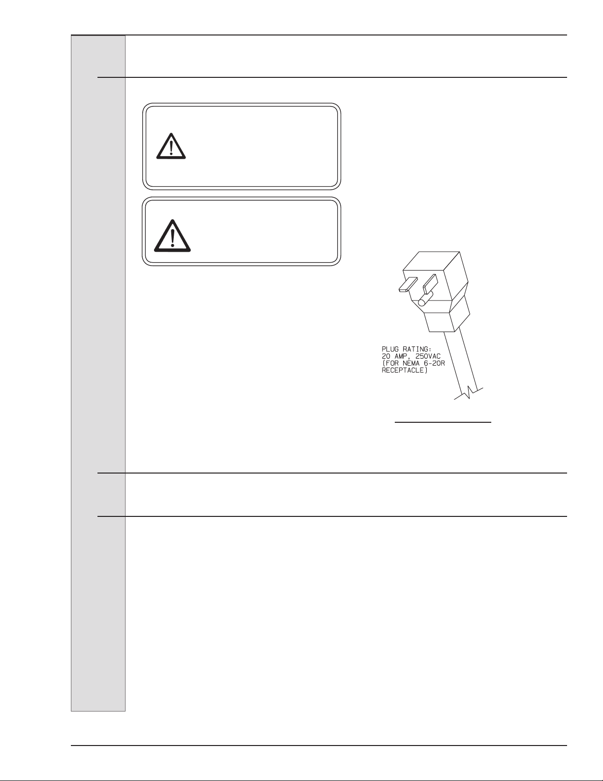
CAUTION
All materials and
connections must conform
to local requirements and
be in compliance with the
National Electric Code (NEC).
CAUTION
To prevent accidental
electrical shock, a receptacle
with a positive earth ground
is required.
1. Always verify electrical
specications on the data plate (gure
3-2) of each individual freezer. Data plate
specications will always supersede the
information in this manual.
2. This freezer requires a protected
20 amp 230 volt circuit. Connect the
freezer to a circuit separate from any
other electrical equipment. The power
cord on this freezer connects to a NEMA
6-20R receptacle. See Figure 2-1.
3. Supply voltage must be within
±10% of voltage indicated on the
nameplate. Request your local power
company to correct any voltage problem.
4. The control transformer in the
electrical box is factory wired to 208 volts
(red) wire tap for 208V nominal power
supply. If power supply is between 230-
240 volts use 240V (orange) wire tap on
transformer.
3.1 Particulars
3 Specifications
Figure 2-1
2.3 Electrical Connections
Width (in/cm) 18.4/46.7
Height (in/cm) 58.9/149.7
Depth (in/cm) 28.1/71.4
Weight (lbs/kg) 250/113.4
Voltage* 208-230/60/1
Min. Circuit Ampacity 20.0
Compressor 1 HP/8000 (BTUH)
.75 kw (Motor)
2.3 kw (Cooling)
Beater Motor 1/2 HP/.37 kw
Refrigerant R-404a
Charge 32.0 oz/.91 kg
Cooling Air
Hopper 20 qts/18.8 liters
Cylinder 7 qts/7.1 liters
*Contact factory for other voltages.

ELECTRO FREEZE Shake Model CS704
185260
4
3.4 Installation Date
Fill in the date of installation, and the name, address, and phone number of the
installer in the space provided below. This information will be needed when ordering
parts or service for the CS704 freezer.
Date of installation: _____________________________________
Installed by: _____________________________________
Address: _____________________________________
_____________________________________
Phone: _____________________________________
The data plate provides important
information that the operator should
record and have available for parts
ordering, warranty inquiries and service
requests.
Figure 3-1
Fill in the following information as soon as
you receive the Electro Freeze CS704.
(The item numbers — encircled, below —
correspond with the call-out numbers in
gure 4-1.)
1.) Model Number: _________________
2.) Serial Number:__________________
3.) Electrical Spec: Voltage ________
Phase _______ Hertz _________
4.) Maximum Fuse Size: ____________
5.) Minimum Circuit Ampacity: _______
Write in Reference
Information HERE!
3.3 Reference Information
3.2 Data Plate
Model:
Ser. No.
~ Volts:
Ph. Hz. Wire:ASSEMBLED IN USA
SINGLE UNIT
Cyl. Compressor RLA LRA V
Beater Motor FLA HP V
Condenser Fan FLA HP V
Hopper Compressor RLA LRA V
Cylinder Refrigerant: Amt:_____LB Type:_____
Design Pressure: High:_____psig Low:_____psig
Hopper Compressor Refrigerant Amt:____ oz Type:____ Design Pressure High:_____psig Low:______psig
Min. Circuit Ampacity: _____A
Max Fuse Size or HACR Cir. Breaker: _____A
ELECTRO FREEZE Shake Model CS704
185260
5
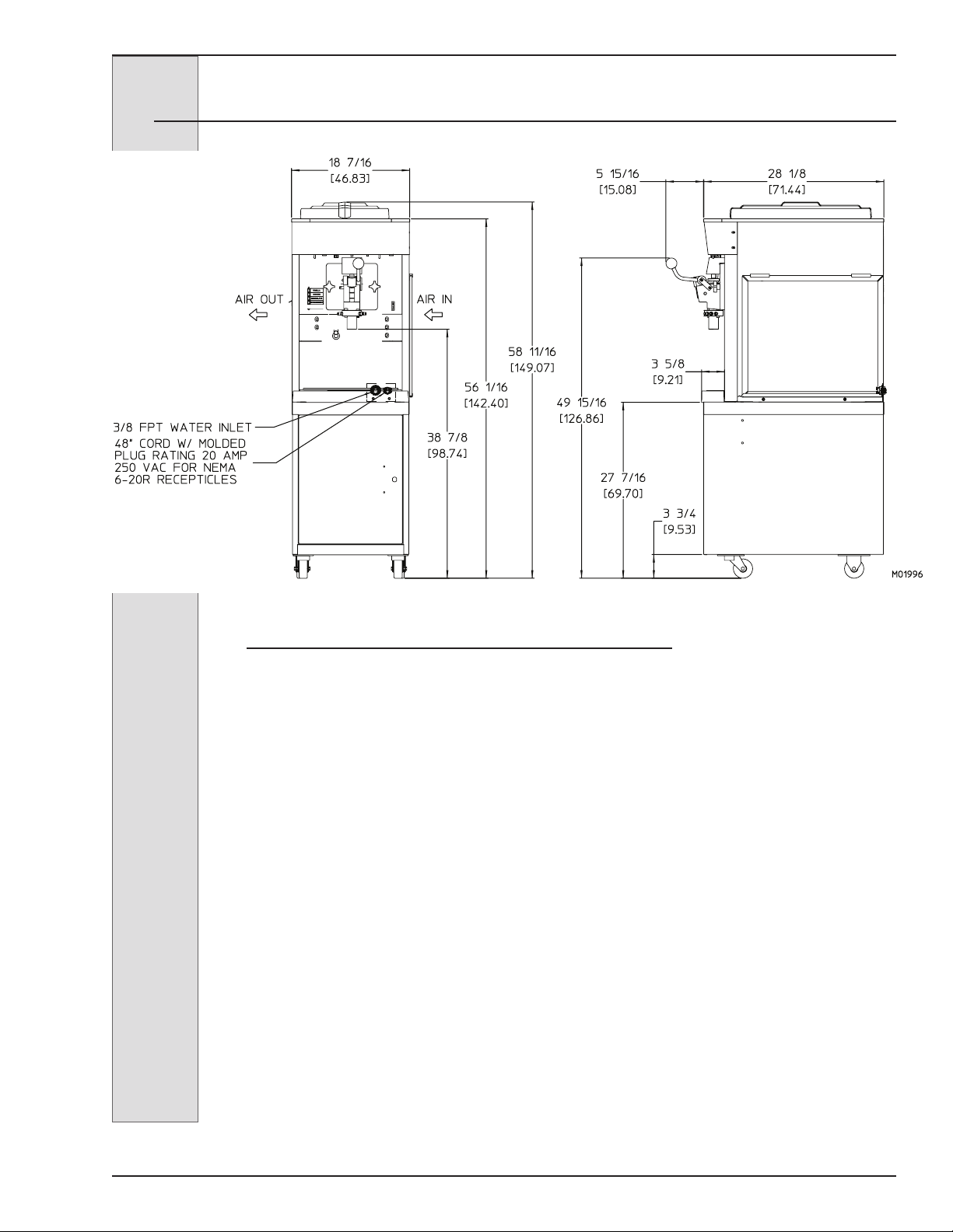
3.5 Dimensions
Figure 3-2 Electro Freeze Model CS704 Dimensions

ELECTRO FREEZE Shake Model CS704
185260
6
4 Part Names and Functions
Figure 4-1 Head Assembly
19
20

ELECTRO FREEZE Shake Model CS704
185260
7
4 Part Names and Functions — continued
1.) COVER - ASSY FLEX SHAFT: Protects
from accidental contact with rotating
shaft. Must be in place to operate.
2.) O-RING - HEAD: Seals the head to the
freezing cylinder. Must be lubricated.
3.) BUSHING - BEATER BEARING: Holds
the beater in place at the front of the
cylinder. Must be inserted into the
head and lubricated before assembly.
4.) KEEPER - ASSY SPINDLE: Secures
the handle to the head.
5.) HEAD - ASSY. W/RETAINERS 4
FLAVOR: Encloses the freezing
cylinder and provides an opening for
product to be dispensed.
6.) QUICK CONNECT WITH SHUT OFF:
Allows syrup line to be removed from
the mix chamber.
7.) O-RING - SYRUP LINE: Prevents syrup
from leaking.
8.) SHAFT - ASSY MIX: Mixes avor into
shake mix.
9.) CHAMBER - MIX: Delivers syrup to the
shake mix.
10.) O-RING - CHAMBER: Prevents mix
from leaking. Lightly lubricate.
11.) HANDLE - ASSY COMPLETE: Opens
and closes the plunger to start and stop
the ow of product from the freezer.
12.) O-RING - PIVOT POST: Holds the pivot
post in place. Lightly lubricate.
13.) POST - PIVOT: Holds the handle in
place.
14.) PLUNGER - DISPENSING: Seals the
product opening in the head when
closed. Allows product to ow when
open.
The following part names and descriptions refer to gure 4-1.
15.) BUSHING - MIXER SHAFT: Holds the
mixing shaft in place. Prevents wear
on plunger.
16.) ROD - ACTUATOR: Starts the freezer
when dispensing. Must be in place
before product can be dispensed.
17.) O-RING - PLUNGER-LOWER
18.) O-RING - PLUNGER-LOWER: Seals
the plunger in the head. Must be
lubricated to seal and slide properly.
19.) SHAFT - FLEXIBLE W/CASING 16-
1/2: Spins the mix shaft.
20.) CONNECT - ASSY DRIVE: Quick
connector used to connect or
disconnect the exible shaft from the
mix shaft
ELECTRO FREEZE Shake Model CS704
185260
8
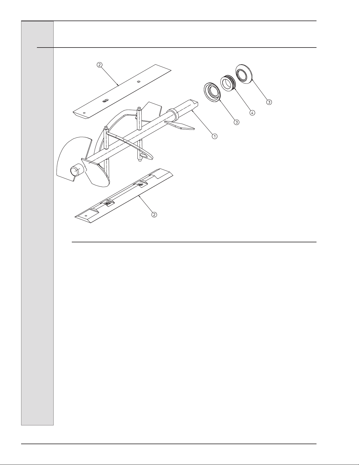
Figure 4-2 Beater Shaft Assembly
1.) SHAFT - BEATER:
Rotates in the
freezing cylinder, blending air and
mix and ejecting product.
2.) BLADE - SCRAPER:
Scrapes the
frozen product from the freezing
cylinder wall.
3.) SEAL (CUP) - BEATER SHAFT:
Seals the opening between the
freezing cylinder and the beater. DO
NOT LUBRICATE.
4.) WASHER - SHAFT SEAL:
Holds
the shaft seals together. Must be
lubricated.
The following part names and descriptions
refer to gure 4-2.
4. Part Names and Functions — continued
SEAL(CUP)-BEATER SHAF
T
BLADE-SCRAPER
WASHER-DOUBLE SHAFT SEAL
BLADE-SCRAPER
SHAFT-BEATER
SEAL(CUP)-BEATER SHAFT

ELECTRO FREEZE Shake Model CS704
185260
9
Figure 4-3 Mix Feed Tube
4. Part Names and Functions — continued
The following part names and descriptions refer to gure 4-3.
1.) TUBE - MIX FEED: Meters the correct
amount of mix and air into the freezing
cylinder from the hopper.
2.) INSERT - ASSEMBLY MIX FEED
(Regulator): Regulates mix ow.
Open position for day operation and
closed position for night.
3.) O-RING - INSERT ASSEMBLY: Holds
the insert in place in the mix tube.
Must be lubricated.
4.) O-RING - MIX FEED ASSEMBLY:
Seals the opening between the
hopper and mix feed tube. O-rings do
not need lubrication.
Tube-Mix Feed
O-Ring
O-Ring
Insert-Assy. Mix
Feed

ELECTRO FREEZE Shake Model CS704
185260
10
The following paragraphs describe
the operator controls and indicators.
Refer to gure 5-1 for location of these
controls and indicators on the freezer.
NOTE: The head, actuator rod, and
metal cover must be in place before the
beater will operate.
—continued
5.1 Syrup Pump Switch (1)
This two-position switch controls the
operating mode of your freezer.
a. “ON” (right) — This position
operates the syrup motor. Always use this
mode when operating the syrup system.
b. “OFF” (left) — In this position
the syrup motors do not run.
5 Operator Controls
CAUTION
Test operation of the head switch
prior to placing the freezer in
service. See Section 12, Routine
Maintenance, Monthly.
Figure 5-1
This manual suits for next models
1
Table of contents
Other H.C Duke & Son Freezer manuals

H.C Duke & Son
H.C Duke & Son Freedom 360 Degrees Series Setup guide

H.C Duke & Son
H.C Duke & Son Electro Freeze FM8 User manual

H.C Duke & Son
H.C Duke & Son 959R Setup guide

H.C Duke & Son
H.C Duke & Son Electro Freeze COMPACT Series User manual

H.C Duke & Son
H.C Duke & Son Electro-Freeze Genesis Series Setup guide

H.C Duke & Son
H.C Duke & Son Electro-Freeze Genesis Series Setup guide


