H.C Duke & Son Electro-Freeze Genesis Series Setup guide

H.C. Duke & Son, LLC. P/N 185240 April 2015 Printed In U.S.A.
OPERATOR’S MANUAL
with Illustrated Parts List
Combination Soft Serve and
Shake Freezer
Model GEN-2080
185240— 4/15


All contents © Copyright 2015 H.C. Duke & Son, LLC., 2116 EighthAvenue, East Moline, Illinois 61244
Operator’s Manual
for
Electro Freeze Combination
Soft Serve and Shake
Freezer Model GEN-2080
i
HC185240

ELECTRO FREEZE Soft Serve Model GEN-1578
The signal words — DANGER, WARNING and
CAUTION— are used with the safety alert symbol
(DANGER decals on the freezer may or may not
have the safety alert symbol, but the message is the
same). Decals with the words DANGER, WARNING
or CAUTION appear on the freezer. DANGER
identies the most serious hazard. Decals with the
words DANGER or WARNING are typically near
specic hazards on the freezer. General precautions
are listed on CAUTION safety decals. In this manual,
CAUTION messages with the safety alert symbol
call attention to safety messages.
1. Recognize Safety Information ....Look for
this safety alert symbol throughout this manual.
When you see this symbol on your freezer or in this
manual, be alert to the potential for personal injury.
Follow recommended precautions and safe operating
practices.
2. Understand Signal Words ....
SAFETY FIRST!
Follow these four steps to safety ....
WARNING
CAUTION
ii
DANGER

ELECTRO FREEZE Soft Serve Model GEN-1578
3. Follow Safety Instructions ....
4. Operate Safely ....
Read and understand all safety messages in this
manual. Read and understand the decal safety
messages on your freezer. Take notice of the location
of all decals on the freezer and keep the safety decals
in good condition. Check them periodically and replace
missing, damaged or illegible safety decals. The safety
decals must remain in place and legible for the life of
the freezer. If you need new decals, use the information
and illustrations on pages v and vi of this manual to
identify the decal and contact your local Electro Freeze
Distributor — or call or write to H.C. Duke & Son, LLC.
DO NOT attempt to operate the GEN-2080 freezer until
you read and understand all safety messages and the
operating instructions in this manual.
SAFETY FIRST!
DO NOT allow untrained personnel to maintain or
service this machine. Failure to follow this instruction
may result in severe personal injury. DO NOT operate
the freezer unless all service panels and access doors
are secured with screws. DO NOT attempt to maintain
or repair the freezer until the main power supply has
been disconnected. Some freezers have more than one
disconnect switch. Contact your local Electro Freeze
Distributor for authorized service.
Safety
First!
iii

ELECTRO FREEZE Soft Serve Model GEN-1578
Do not attempt to operate the freezer
until all safety precautions and operating
instructions in this manual are read and
understood.
Take notice of all warning, caution,
instruction and information decals (or
labels) on the freezer as shown in the
gure to the right. The labels have been
put there to help maintain a safe working
environment.
The labels have been designed to with-
stand washing and cleaning. All labels
must remain legible for the life of the
freezer. Check labels periodically to be
sure they can be recognized as warning
labels.
If it is necessary to replace any label,
please contact your local authorized
Electro Freeze Distributor or H. C. Duke
& Son, LLC. When ready to order, you will
need to determine the (1) part number,
(2) type of label, (3) location of label, and
(4) quantity required, and include a return
shipping address.
Safety Decal Locations
You may contact your local authorized
Electro Freeze Distributor, as follows:
Name:
Address:
Phone:
or, for factory service assistance,contact
H. C. Duke & Son, Electro Freeze Service
Department by phone, FAX or e-mail:
Phone: (309) 755-4553
(800) 755-4545
FAX: (309) 755-9858
(The decals on the next page are
numbered 1, 2, 3 and 4. Those numbers
correspond to the numbers in the table
below. The table provides the part
number, description, and quantity for each
decal.)
No. Part No. Description (Qty)
1 HC165025 Decal — Beater Warning (1)
2 HC165246 Decal — Pressurized System Warning (2)
3HC165048 Decal — Warning Rotating Parts (2)
4HC165126 Decal — Panel Removal Warning (3)
iv

ELECTRO FREEZE Soft Serve Model GEN-2080
185240 vii
Safety Decal Locations
HC165025
1
HC165246
2
HC165048
3
HC165126
4
Pressurized system.
Depressurize unit
before dismantling mix
transfer system.
Do not
operate
with cover
removed!
165048

ELECTRO FREEZE Soft Serve Model GEN-1578
Table of Contents
vi
Safety First ................................................................................................... ii
Safety Decal Locations................................................................................... iv
Part I
1 Introduction ......................................................................... 1
2 Note to Installer ................................................................... 1
2.1 Uncrating and Inspection............................................................. 2
2.2 Installation.................................................................................... 2
2.3 Electrical Requirements............................................................... 3
2.4 Electrical Connections ................................................................. 3
3 Specications ...................................................................... 4
3.1 Particulars.................................................................................... 4
3.2 Installation Date........................................................................... 4
3.3 Data Plate.................................................................................... 5
3.4 Reference Information ................................................................. 5
3.5 Dimensions.................................................................................. 6
4 Part Names and Functions — Soft Serve............................ 8
5 Part Names and Functions — Shake .................................. 14
6 Operator Controls ................................................................ 18
7 Operator Display Menu................................................................. 21
8 Disassembly and Cleaning — Soft Serve............................ 24
8.1 Cleaning Accessories................................................................... 25
8.2 Disassembly Instructions............................................................. 26
8.3 Cleaning Instructions ................................................................... 29
8.3.1 Cleaning & Lubricating MTS Assembly...................................... 31
9 Disassembly and Cleaning — Shake .................................. 33
9.1 Cleaning Accessories ......................................................... 34
9.2 Disassembly Instructions............................................................. 36
9.3 Cleaning Instructions ................................................................... 37
9.3.1 Cleaning and Lubricating MTS Assembly .................................. 39

ELECTRO FREEZE Soft Serve Model GEN-1578
vii
Table of Contents — continued
10 Assembly — Soft Serve....................................................... 40
11 Assembly — Shake ..................................................................... 45
12 Start-up Instructions — Soft Serve ........................................... 51
12.1 Sanitizing Instructions ................................................................ 51
12.2 Priming....................................................................................... 52
13 Start-up Instructions — Shake ............................................ 53
13.1 Sanitizing Instructions ................................................................ 54
13.2 Priming....................................................................................... 55
14 Closing Procedures ............................................................. 56
14.1 Night Switch Operation............................................................... 56
14.2 Draining Product......................................................................... 56
15 Product Information ............................................................. 58
15.1 Overrun ...................................................................................... 58
15.2 Overrun Adjustment.................................................................... 59
15.3 Rerun.......................................................................................... 59
16 Routine Maintenance........................................................... 60
17 Troubleshooting Table ......................................................... 66
18 VQM Error Codes ................................................................ 75
Part II
Model GEN-2080 Replacement Parts Manual with Illustrations............ *
* Refer to Part II Table of Contents


ELECTRO FREEZE Soft Serve Model GEN-2080
185240 1
1 Introduction
The GEN-2080 Freezer is designed to
produce soft serve ice cream, ice milk,
yogurt, and similar frozen dairy products,
with a product serving temperature range
of 15 to 25°F (-9 to -4°C). It also produces
shakes with a product temperature of
26°F (-3°C). If such products are prepared
from powdered concentrate, they should
be precooled to 40ºF (4°C) prior to
introduction to the freezer. Use of other
products in this machine is considered
misuse (see Warranty).
This manual has been prepared to assist
you in the proper operation and general
maintenance of the Electro Freeze Soft
Serve and Shake Freezer Model GEN-
2080.
Your freezer will not compensate for or
correct any assembly or priming errors
made during the initial start-up. Therefore,
it is important to follow the assembly
and priming procedures detailed in this
manual.
Make sure all personnel responsible for
equipment operation completely read and
understand this manual before operating
the freezer. When properly operated and
maintained, the freezer will produce a
consistent quality product.
If you require technical assistance, please
contact your local authorized Electro
Freeze Distributor as follows:
Name:__________________________
Address: ________________________
________________________________
Phone: __________________________
For factory service assistance — contact
H. C. Duke & Son, LLC., Electro Freeze
Service Department as follows:
Phone: (309) 755-4553
(800) 755-4545
FAX: (309) 755-9858
2 Note to Installer
This freezer must be installed and serviced by an Electro Freeze Distributor or
authorized service technician.
After installation the warranty registration card must be completed and
returned to validate the warranty.

ELECTRO FREEZE Soft Serve Model GEN-2080
2 185240
2.1 Uncrating and Inspection
Figure 2-1 Machine Bolted to Shipping Base
CAUTION
Be sure to properly support
the machine when removing
bolts and installing legs or
casters.
When the unit is received and while
the carrier is still present, inspect the
shipping carton for any damage that
may have occurred in transit. If the
SHOCKWATCH®label indicates red and/
or the carton is broken, torn, or punctured,
note the damage on the carrier’s freight
bill and notify the carrier’s local agent
immediately.
1. Remove the carton from the
pallet, and move the machine as close as
possible to the permanent location.
2. Remove the shipping bolts on
the bottom of the freezer (gure 2-1) and
install either the legs or casters (gure
2-2).
Figure 2-2 Installing Mounting Legs or Casters
2.2 Installation
CAUTION
All materials and connections
must conform to local
requirements and be in
compliance with the National
Electrical Code (NEC).
1. This freezer is designed for indoor
use and must be protected from outdoor
weather conditions.
– continued
NOTE: Screw casters
or legs all the way in
coupling, then adjust
out to level side to side
with a 1/4” slope to the
front.

ELECTRO FREEZE Soft Serve Model GEN-2080
185240 3
2. Where codes permit, we
recommend that the freezer be installed
on casters and have exible water and
electrical connections for service and
cleaning ability.
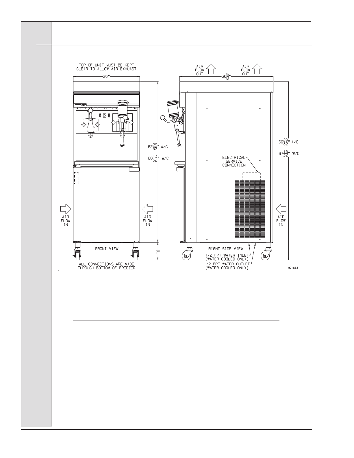
3. All models require a minimum 6
inch (15 cm) clearance on either the side
panels or the rear panel for adequate
ventilation. Freezers designed with top air
discharge require that at least 18 inches
(45 cm) above the top panel be free of
obstructions. Anything blocking ventilation
of the freezer (including cone dispensers)
will reduce the efciency of the freezer.
4. Water cooled models will require
a 1/2 inch MPT water inlet and water
waste connection. Both condensers are
2.3 Electrical Requirements
2.2 Installation (continued)
3. Refer to the wiring diagram
provided for proper power connections.
4. Electrical connections are made in
the junction box located mid-level behind
the left side panel.
5. Use a exible connection when
permissible. All materials and connections
must conform to local codes and the
National Electrical Code.
6. For 3 phase freezers, beater shaft
rotation must be clockwise as viewed
from the front of the freezer.
2.4 Electrical Connections
1. Double freezers with two
compressors require one power supply for
each side of the freezer. Each side of the
freezer operates independently.
2. Check the data plate for fuse
size, wire ampacity and electrical
specications.
tied together so that one water inlet and
one water waste is all that is required.
The connections are found on the bottom
under the compressor mounting area
and are tagged “Water Inlet” and “Water
Waste.” A manual shut-off valve should be
installed in the water inlet line at the time
of installation. The water pressure must
be above 35 psig (241 kPa) and below
140 psig (965 kPa) for proper operation.
5. Place the freezer in the nal
location and level by adjusting the legs or
casters so that it is level side-to-side and
the front is approximately ¼ inch lower
than the rear (to allow proper drainage of
the freezing cylinder).
2. Supply voltage must be within
+ 10% of voltage indicated on the
nameplate. Also, on three-phase
systems, voltage between phases must
be balanced within 2%. (More than a 6
volt difference between any two voltage
measurements at 208-230 volts indicates
a possible imbalance.) Request your local
power company to correct any voltage
problem.
3. An easily accessible main power
disconnect must be provided for all poles
of the wiring to the freezer.
1. Always verify electrical
specications on the data plate of each
freezer. Data plate specications (see
Figure 3-1) will always supersede the
information in this manual.
CAUTION
To prevent acciden-
tal electrical shock, a
positive earth ground is
required.
CAUTION
To prevent accidental elec-
trical shock, a positive earth
ground is required.

ELECTRO FREEZE Soft Serve Model GEN-2080
4 185240
3.1 Particulars
Always check and verify voltage and amperage on the data
plate located on the back panel of each freezer.
3 Specifications
Fill in the date of installation, and the name, address, and phone number of the
installer in the space provided below. This information will be needed when ordering
parts or service for the GEN-2080 Freezer.
Date of installation: ___________________________________
Installed by: ___________________________________
Address: ___________________________________
___________________________________
Phone: ___________________________________
3.2 Installation Date
GEN-2080 Combination Soft Serve and Shake Freezer
Width (in/cm) 26 / 66
Height (in/cm) 70 / 178 (Air Cooled Models)
67.5 / 172 (Water and Air Cooled Remote Models)
Depth (in/cm)36.5 / 93
Weight (lbs/kg) 852 / 408
Soft Serve Shake
Compressors 2 HP / 9500 BTU 2 HP 12000 BTU
1.5 kw (Motor) 1.5 kw (Motor)
2.8 kw (Cooling) 2.8 kw (Cooling)
Beater Motor2 HP / 1.5 kw 1 .5 HP / 1.1 kw
Refrigerant 404a 404a
Charge 3.75 lb. / 1.7 kg 3.75 lb. / 1.7 kg
Mix Container 30 qts. / 28.4 L 28 qts. / 26.5 L
Cylinder 4 Qts. / 3.8 L 9 Qts. / 8.51 L

ELECTRO FREEZE Soft Serve Model GEN-2080
185240 5
3.3 Data Plate
The data plate provides important infor-
mation that the operator should record
and have available for parts ordering,
warranty and service requests.
Figure 3-1
3.4 Reference Information
Write in
Reference
Information HERE!
Fill in this information as soon as you
receive the Electro Freeze GEN-2080
Soft Serve/Shake Freezer. The item
numbers, encircled, correspond with the
call-out numbers in gure 3-1.
1.) Model Number: ________________
2.) Serial Number: ________________
3.) Electrical Spec: Voltage _________
Phase _______ Hertz _________
4.) Maximum Fuse Size: ____________
5.) Minimum Circuit Ampacity:________

ELECTRO FREEZE Soft Serve Model GEN-2080
6 185240
Figure 3-2
3.5 Dimensions
W/C = Water Cooled Models
A/C = Air Cooled Models
ACR = Air Cooled Remote Models dimensions are the same as W/C
MODEL GEN-2080

ELECTRO FREEZE Soft Serve Model GEN-2080
185240 7
Please note that in the following pages of this manual,
some sections relate specifically to either the “Soft
Serve” side of the freezer or the “Shake” side of the
freezer. The GEN-2080 combination freezer actually
contains two separate systems — one side provides
soft serve ice cream and the other, shakes. Although
there are some part and procedure similarities
between the shake and soft serve sides, we have
separated them to make it easier for you to find the
information you need. You may notice a duplication of
some information. Where feasible the information is
only provided once, for both sides.
Look for the Electro Freeze Cone and term “Soft
Serve” in the section header for instructions
concerning the frozen dessert side of the freezer.
Look for the Electro Freeze Shake and the term
“Shake” in the section header for instructions
concerning the shake side of the freezer.
NOTE: Combination Soft Serve/Shake
Freezers

ELECTRO FREEZE Soft Serve Model GEN-2080
8 185240
4 Part Names and Functions — Soft Serve
Figure 4-1 Head Assembly
HEAD-
DISPENSE
NOZZLE
PLUNGER
O-RING-PLUNGER
O-RING-PLUNGER
O-RING-HEAD
ROD-PLUNGER
PLUG-AIR BLEED
O-RING-PLUG
PIN-HANDLE
HANDLE-DISPENSE
KNOB-HAND

ELECTRO FREEZE Soft Serve Model GEN-2080
185240 9
4 Part Names and Functions — Soft Serve
The following descriptions apply to gure 4-1. The number preceding the
part name corresponds to the number in the gure.
1.) HEAD: Encloses the freezing
cylinder and provides an opening for
product to be dispensed.
2.) NOZZLE: Shapes the frozen
product as it is dispensed.
3.) KNOB-HAND: Secures the
dispensing head to the freezing
cylinder.
4.) HANDLE-DISPENSE: Opens and
closes the plunger to start and stop
the ow of product from the freezer.
5.) PIN-HANDLE: Secures the handle
to the dispense head.
6.) O-RING-PLUG: Seals the air bleed
plug in the dispense head.
7.) PLUG-AIR BLEED: Seals the air
bleed opening in the head when
closed. Allows excess air to be
removed from the cylinder in the
lling process.
8.) ROD-PLUNGER: Starts the freezer
when dispensing. Must be in place
before freezer will operate.
9.) PLUNGER: Seals the product
opening in the head when closed.
Allows product to ow when open.
10.) O-RING-PLUNGER-UPPER: Seals
the plunger in the dispensing head.
Must be lubricated to seal and slide
properly.
11.) O-RING-PLUNGER-LOWER: Seals
the plunger in the dispensing head.
Must be lubricated to seal and slide
properly.
12.) O-RING-HEAD: Seals the
dispensing head to the freezing
cylinder. Must be lubricated.

ELECTRO FREEZE Soft Serve Model GEN-2080
10 185240
4 Part Names and Functions — Soft Serve
Figure 4-2 Soft Serve Beater Shaft Assembly
Other manuals for Electro-Freeze Genesis Series
1
This manual suits for next models
1
Table of contents
Other H.C Duke & Son Freezer manuals

H.C Duke & Son
H.C Duke & Son Freedom 360 Degrees Series Setup guide

H.C Duke & Son
H.C Duke & Son 959R Setup guide

H.C Duke & Son
H.C Duke & Son Electro Freeze COMPACT Series User manual

H.C Duke & Son
H.C Duke & Son Electro Freeze FM8 User manual

H.C Duke & Son
H.C Duke & Son Arby's Electro Freeze Compact Series Manual

H.C Duke & Son
H.C Duke & Son Electro-Freeze Genesis Series Setup guide