H.C Duke & Son Electro Freeze COMPACT Series User manual

H. C. Duke & Son, LLC P/N 184596 July 2013 Printed in U.S.A.
C
OMPACT SERIES
SOFT SERVE FREEZER
Model CS600
184596 - 7/13
OPERATOR'S MANUAL
with Illustrated Parts List


Operator’s Manual
for the
Electro Freeze Model CS600
Compact Series
Soft Serve Freezer
All contents © Copyright 2012 H.C. Duke & Son, LLC, 2116 Eighth Avenue, East Moline, Illinois 61244
i

ELECTRO FREEZE Model CS600
184596
When you see this symbol on your freezer or in this
manual, be alert to the potential for personal injury.
Follow recommended precautions and safe
operating practices.
WARNING
CAUTION
The signal words — DANGER, WARNING and
CAUTION — are used with the safety alert symbol
(DANGER decals on the freezer may or may not
have the safety alert symbol, but the message is the
same). Decals with the words DANGER, WARN-
ING or CAUTION appear on the freezer. DANGER
identifies the most serious hazard. Decals with the
words DANGER or WARNING are typically near
specific hazards on the freezer. General precautions
are listed on CAUTION safety decals.
In this manual, CAUTION messages with the safety
alert symbol call attention to safety messages.
ii
SAFETY FIRST!SAFETY FIRST!
SAFETY FIRST!
Follow these four steps to safety ....
DANGER
2. Understand Signal Words ....
1. Recognize Safety Information ....Look fLook f
Look fLook f
Look for this safor this saf
or this safor this saf
or this safetyety
etyety
ety
aleraler
aleraler
alert symbol thrt symbol thr
t symbol thrt symbol thr
t symbol throughout this manoughout this man
oughout this manoughout this man
oughout this manual.ual.
ual.ual.
ual.

ELECTRO FREEZE Model CS600
184596
SAFETY FIRST!SAFETY FIRST!
SAFETY FIRST!
iii
3. Follow Safety Instructions ....
Read and understand all safety messages in this
manual. Read and understand the decal safety
messages on your freezer. Take notice of the
location of all decals on the freezer and keep the
safety decals in good condition. Check them
periodically and replace missing, damaged or
illegible safety decals. The safety decals must
remain in place and legible for the life of the
freezer. If you need new decals, use the
information and illustrations on pages iv and v of
this manual to identify the decal and order
replacement parts.
DO NOT attempt to operate the CS600 freezer
until you read and understand all safety
messages and the operating instructions in this
manual.
4. Operate Safely ....
DO NOT allow untrained personnel to maintain or
service this machine. Failure to follow this
instruction may result in severe personal injury. DO
NOT operate the freezer unless all service panels
and access doors are secured with screws. DO
NOT attempt to maintain or repair the freezer until
the main power supply has been disconnected.
Contact your local Electro Freeze Distributor for
authorized service.

ELECTRO FREEZE Model CS600
184596
iv
Safety Decal Locations
Do not attempt to operate the freezer until
all safety precautions and operating
instructions in this manual are read and
understood.
Take notice of all warning, caution, instruc-
tion and information decals (or labels) on
the freezer as shown in the figure on the
following page. The labels have been put
there to help maintain a safe working
environment.
The labels have been designed to with-
stand washing and cleaning. All labels
must remain legible for the life of the
freezer. Check labels periodically to be
sure they can be recognized as warning
labels.
If it is necessary to replace any label,
please contact your local authorized
Electro Freeze Distributor or H. C. Duke &
Son. When ready to order you will need to
determine the (1) part number, (2) type of
label, (3) location of label, and (4) quantity
required, and include a return shipping
address.
You may contact your local authorized
Electro Freeze Distributor, as follows:
Name:
Address:
Phone:
or —for factory service assistance —contact
H. C. Duke & Son, LLC, Electro Freeze
Service Department by phone or FAX:
Phone: 309-755-4553
800-755-4545
FAX: 309-755-9858
E-mail: [email protected]
(The decals on the next page are numbered
1 and 2. Those numbers correspond to the
numbers in the table below. The table
provides the part number, description, and
quantity for each decal.)
(
No. Part No. Description (Qty)
1HC165126 Decal — Panel Removal Warning (3)
2HC165025 Decal — Beater Warning (1)

ELECTRO FREEZE Model CS600
184596
Safety Decal Locations
v
WARNING
!
Hazardous moving parts.
Machine starts automatically.
Do not operate with panel
removed.
1 P/N HC165126
2 P/N HC165025
Hazardous rotating beater shaft. Do not
operate unit with dispense head removed.
Before removing dispense head:
1. Turn all control switches to "OFF", and
2. Disconnect all power supplies. Unit
may have more than one power supply.

ELECTRO FREEZE Model CS600
184596
Table of Contents
SECTION DESCRIPTION PAGE
SAFETY .......................................................................................... ii
PART I
1. INTRODUCTION ............................................................................ 1
2. NOTE TO INSTALLER ................................................................. 1
3. ELECTRICAL REQUIREMENTS ............................................. 2
4. SPECIFICATIONS .......................................................................... 2
4.1 Particulars. .................................................................................... 2
4.2 Data Plate ...................................................................................... 3
4.3 Reference Information ................................................................... 3
4.4 Installation Date ............................................................................ 3
4.5 Dimensions. ................................................................................... 4
5. PART NAMES AND FUNCTIONS ............................................ 5
6. OPERATOR CONTROLS & INDICATORS ........................... 7
6.1 Selector Switch ............................................................................. 7
6.2 Day-Night Switch ........................................................................... 7
6.3 "ADD MIX" Indicator Light .............................................................. 7
6.4 Mix Float ........................................................................................ 8
6.5 Mix Feed Tube & Insert .................................................................. 8
7. DISASSEMBLY AND CLEANING ............................................ 9
7.1 Accessories ................................................................................... 9
7.2 Disassembly Instructions ............................................................. 10
7.3 Cleaning Instructions................................................................... 11
8. ASSEMBLY..................................................................................... 13
9. START-UP INSTRUCTIONS .................................................... 15
9.1 Sanitizing ..................................................................................... 15
9.2 Priming ........................................................................................ 16
vi

ELECTRO FREEZE Model CS600
184596
Table of Contents - continued
SECTION DESCRIPTION
PAGE
10. CLOSING PROCEDURES ....................................................... 17
10.1 Night Switch Operation ............................................................... 17
10.2 Draining Product From Freezer................................................... 18
11. SOFT SERVE INFORMATION ................................................ 19
11.1 Overrun ....................................................................................... 19
11.2 Rerun ........................................................................................... 19
12. ROUTINE MAINTENANCE ..................................................... 20
13. TROUBLESHOOTING TABLE ............................................... 23
PART II
MODEL CS600 REPLACEMENT PARTS WITH ILLUSTRATIONS *
* Refer to Part II Table of Contents for help with locating part numbers and illustrations.
vii

ELECTRO FREEZE Model CS600
184596 1
1 Introduction
The CS600 freezer is designed to produce
soft serve ice cream, ice milk, yogurt, and
similar frozen dairy products, with a product
serving temperature range of 15° to 25ºF (-9°
to -4°C). If such products are prepared from
powdered concentrate, they should be
precooled to 40ºF (4°C) prior to introduction
to the freezer. Use of other products in this
machine is considered misuse (see War-
ranty).
This manual has been prepared to assist
you in the proper operation and general
maintenance of the Electro Freeze
Model CS600 freezer.
Make sure all personnel responsible for
equipment operation completely read
and understand this manual before
operating the freezer. When properly
operated and maintained the freezer will
produce a consistent quality product.
If you require technical assistance, please
contact your local authorized Electro Freeze
Distributor, as follows:
Name:
Address:
Phone:
Forfactoryserviceassistance —contact
H.C. Duke & Son, LLC, Electro Freeze
ServiceDepartmentasfollows.
Phone: 309-755-4553
800-755-4545
FAX: 309-755-9858
E-mail: [email protected]
((
((
(
2 Note to Installer
This freezer must be installed and
serviced by an Electro Freeze Distribu-
tor or authorized service technician in
accordance with the installation instruc-
tions in this manual.
Verify the weight of the freezer. Ensure a
counter or table of sufficient strength is
used to hold this weight and prevent exces-
sive vibration.
All models require a minimum of 3-inches
(7.6 cm) air space on both sides and back
of the freezer for adequate ventilation.
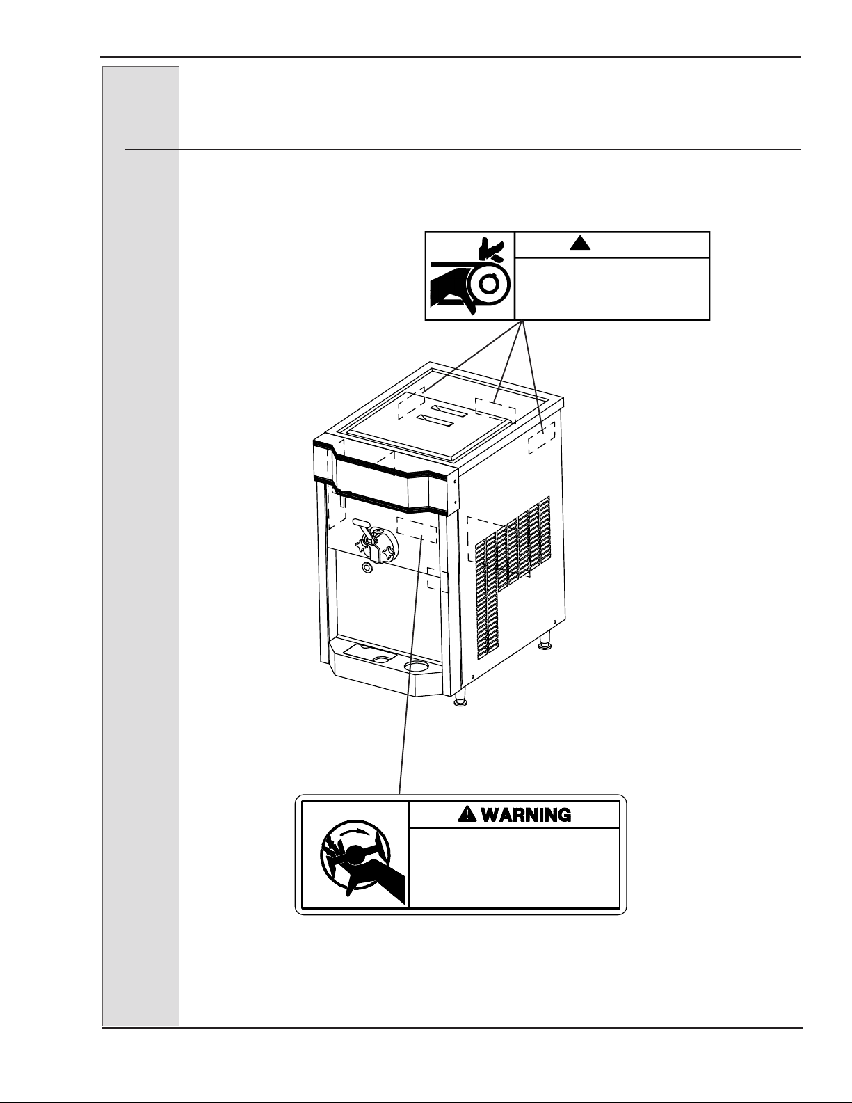
If this freezer is to be used in a self-service
application, it is recommended that the
machine be fitted with a self-service kit.
Contact your Electro Freeze Distributor or
H. C. Duke & Son, LLC. for this kit.
Test the operation of the head safety switch
prior to placing the freezer in service. See
Section 12, Routine Maintenance, Monthly.
After installation the warranty registration
card must be completed and returned to
validate the warranty.

ELECTRO FREEZE Model CS600
2184596
CAUTION
All materials and connec-
tions must conform to
local requirements and be
in compliance with the
National Electric Code
(NEC).
CAUTION
To prevent accidental
electrical shock, a
receptacle with a positive
earth ground is required.
1. Always verify electrical specifi-
cations on the data plate (figure 4-1) of
each individual freezer. Data plate
specifications will always supersede
the information in this manual.
2. This freezer
requires a protected
20 amp 208/230 volt
circuit. Connect the
freezer to a circuit
separate from any
other electrical
equipment. The
power cord on this
freezer connects to a
NEMA 5-20R recep-
tacle. See Figure 3-
1.
3. Supply
voltage must be
within ±10% of
voltage indicated on
the nameplate.
3 Electrical Requirements
4.1 Particulars
4 Specifications
Width (in/cm) 18-3/8 / 46.7
Height (in/cm) 35-13/64 / 89.4
Depth (in/cm) 28-3/32 / 71.4
Weight (lbs/kg) 240/109
Voltage* 208-230/60/1
Min.Circuit Ampacity20.0
Compressor 1-1/2 HP/6500(BTUH)
1.1kw (Motor)
1.9 kw (Cooling)
Beater Motor 1-1/2 HP / 1.1kw
Refrigerant R-404a
Charge 20-34 oz/.57-.96kg
Cooling Water / Air
Hopper 22 qts/21.2 liters
Cylinder 3.7 qts/3.5 liters
*Contact factory for other voltages.
Figure 3-1

ELECTRO FREEZE Model CS600
184596 3
4.2 Data Plate
The data plate provides important
information that the operator should
record and have available for parts
ordering, warranty inquiries and service
requests.
Figure 4-1
4.3 Reference Information
Fill in the following information as soon as
you receive the Electro Freeze CS600. (The
item numbers — encircled, below — corre-
spond with the callout numbers in figure 4-1.)
1Model Number: _________________
2Serial Number:__________________
3Electrical Spec: Voltage ________
Phase _______ Hertz _________
4Maximum Fuse Size: ____________
5 Minimum Circuit Ampacity: _______
4.4 Installation Date
Write in Reference
Information HERE!
E
Fill in the date of installation, and the name, address, and phone number of the installer in
the space provided below. This information will be needed when ordering parts or service for
the CS600 Freezer.
Date of installation: _____________________________________
Installed by: _____________________________________
Address: _____________________________________
_____________________________________
Phone: _____________________________________

ELECTRO FREEZE Model CS600
4184596
Figure 4-2 Electro Freeze Model CS600 Dimensions
4.5 Dimensions
The dimensions of the CS600 freezer are
provided in figure 4-2, below.
*Optional Top Air Discharge Chute, p/n HC120991
Figure 4-3 Optional Stainless Steel Cart, p/n HC162200 is available
28 1/8
71.4
27 3/4
70.5
Side View
28 1/8” deep
18 1/16” wide
27 3/4” height
*
*

ELECTRO FREEZE Model CS600
184596 5
5Part Names and Functions
Figure 5-1 Head Assembly
5 PLUNGER. Seals the product
opening in the head when closed. Allows
product to flow when open.
6 HANDLE - DISPENSE. Opensand
closes the plunger to start and stop the flow
of product from the freezer.
7 PIN - HANDLE. Secures handle to
thehead.
8 KNOB - HAND. Secures the head
to the freezing cylinder.
9 NOZZLE. Shapesthefrozen
product as it is dispensed.
1 HEAD. Encloses the freezing
cylinderandprovidesanopeningforproduct
to be dispensed.
2 O-RING - HEAD. Seals the head
to the freezing cylinder. Must be lubricated.
3 O-RING - PLUNGER. Seals the
plunger in the head. Must be lubricated to
seal and slide freely.
4 ROD - PLUNGER. Starts the
freezer when dispensing. Must be in place
beforefreezerwilloperate.
HANDLE -
DISPENSE
KNOB -
HAND
ROD - PLUNGER
PLUNGER
O-RING - PLUNGER
O-RING - HEAD
DISPENSE - HEAD
PIN - HANDLE
NOZZLE

ELECTRO FREEZE Model CS600
6184596
5Part Names and Functions
1BAR-BREAKER.Keepsproduct
blended in the center of the beater shaft.
2SHAFT-BEATER.
Rotatesinthe
freezing cylinder blending air and mix. Ejects
productwhendispensingplungerisopened.
3BLADE-SCRAPER Scrapesfrozen
product from cylinder walls.
SEAL- SHAFT.Sealsthe openingbetween
the freezing cylinder and the beater shaft.
consists of:
4SEAL-BEATERSHAFT
5WASHER-DOUBLESHAFT
SEAL
1TUBE- MIX FEED.188. Metersthe
correct amount of mix and air into the
freezing cylinder from the hopper.
2O-RING-TUBE.
Sealstheopening
between the hopper and mix feed tube. (O-
rings do not need lubrication.)
3INSERT-ASSYMIXFEED. Providesa
positive shut off of mix flow to the freezing
cylinder.
4O-RING-INSERT. Holds theinsert
tube in place in the mix tube. Must be
lubricated.
Figure 5-2 Beater Shaft Assembly
Figure 5-3 Mix Feed Tube Assembly
O-RING
O-RING INSERT-ASSY. MIX FEED
TUBE-MIX FEED
2
3
4
1

ELECTRO FREEZE Model CS600
184596 7
l
6.1 Selector Switch 1
This three-position switch selects the
mode of operation of the freezer.
a. “CLEAN” (left) — This position
operates the beater only (no refrigera-
tion). Always use this mode when
performing cleaning and sanitizing
operations.
b. “OFF” (center) — In this position
the beater motor and refrigeration
system will not operate.
Important:
Do not use the automatic position
with water or sanitizer in the cylinder
or hopper — the freezer will be dam-
aged.
c. “AUTO” (right) — This position
activates both the beater motor and
refrigeration unit. This is the normal
operating position.
6.2 Day– Night Switch 2
a. “DAY” (left) — The low tempera-
ture thermostat controls the system
refrigeration to maintain the product
serving temperature between 18
°
–21°F
(-8 to -6°C). This is the normal operating
position.
b. “NIGHT” (right) — This energy
saving mode will reduce product agita-
tion. The freezer will automatically cycle
to maintain temperatures below 41
º
F (5
º
C). Use this position when the freezer
will not be in use for periods of more
than an hour.
6.3 “ADD MIX” Indicator Light 3
Figure 6-1
CAUTION
Test operation of the head
switch prior to placing the
freezer in service. See Section
12, Routine Maintenance,
Monthly.
6 Operator Controls
The following paragraphs describe the
operator controls and indicators. Refer to
figure 6-1 for location of these controls and
indicators on the Model CS600 freezer.
NOTE: The plunger rod must be in place
before the freezer will operate in “DAY”,
“NIGHT”, or “CLEAN” position.
Important:
If proper mix level is not maintained,
a freeze-up may occur and damage
the freezer.
When lit, this light indicates the mix in
the hopper is at a low level and should
be refilled as soon as possible. Always
maintain at least 2 inches (5 cm) of mix
in the hopper. For best operating results
keep hopper full.

ELECTRO FREEZE Model CS600
8184596
6 Operator Controls – continued
This two-position regulating device
(figure 6-3) meters the correct amount
of mix and air into the freezing cylinder.
a. “OPEN” - Always use this position
when dispensing product. (See figure 6-4.
When OPEN you can see clear through the
hole in the top of mix feed tube.)
Important:
If product is dispensed when the
regulator is in the “CLOSED” posi-
tion, a freeze-up will occur and may
damage the freezer.
b. “CLOSED” - Use this position
when the freezer is in the “NIGHT”
mode, and when product will not be
dispensed for a long period of time.
(See figure 6-4. When CLOSED you
cannot see through the hole in the top
of the mix feed tube — the white plastic
insert tube inside will block the hole.)
Figure 6-3
Figure 6-4
6.4 Mix Float (not shown)
6.5 Mix Feed Tube & Insert
Pin
Location
Pin
Location
Insert-Assy.
Miix Feed
When this float is mounted on the float
stem inside the hopper it automatically
senses the mix level. It activates the “Add
Mix” light

ELECTRO FREEZE Model CS600
184596 9
7Disassembly and Cleaning
7.1 Cleaning Accessories
The following are accessories necessary for cleaning, sanitizing and disassembly/
assembly.
1. BRUSH - HC158009.4-inch diam-
eter used to clean the cylinder.
2. HANDLE - HC158012. 36-inch
handle used with brush p/n HC15010.
3. BRUSH - HC158077.9/16-inch in
diameter with 36-inch handle used to clean
drain tube.
4. BRUSH - DOUBLE END -
HC158003.1-1/8-inch diameter and 7/16-
inch diameter used for cleaning mix feed
tube and general cleaning.
5. TOOL - O-RING REMOVAL.
HC169374. Aids in removing O-rings from
plunger, head, air relief plug, and spindle.
6. LUBRICANT - LUBRI-FILM PLUS
HC158054A.Approved lubricant for moving
parts and O-rings.
7. BRUSH - HC158026.1-inch in
diameter 12 inches long used to clean the
hopper walls.
8. WASH BOTTLE - HC196103.used
to flush the plunger and hopper walls.
Figure 7-1 Accessories
HC158009 BRUSH-4” DIA
HC158077 BRUSH-9/16” DIA X 36” HANDLE
HC158012 HANDLE-BRUSH 36” FIBERGLASS
HC169374 TOOL-O RING REMOVAL
HC158003 BRUSH-7/16” DIA & 1-1/8” DIA DOUBLE END
HC158026 BRUSH-1” DIA X 12” LONG
HC158054A LUBRICANT-LUBRI-FILM PLUS
HC196103 BOTTLE WASH
CAUTION
To avoid electrical shock or
contact with moving parts,
make sure all switches are
in the “OFF” position and
that the main power supply
is disconnected.
It is important that the freezer be disas-
sembled, washed, lubricated and sanitized
before operation.
The cleaning and sanitizing instructions
explained in this manual are required to
maintain a clean, sanitary freezer. The
freezer should be disassembled, cleaned,
reassembled, lubricated and sanitized to
ensure the best possible product quality
and freezer operation.
Persons assembling, cleaning, or sanitizing
the freezer must wash and sanitize hands
and forearms with an approved sanitizer.

ELECTRO FREEZE Model CS600
10 184596
7.2 Disassembly Instructions
CAUTION
To avoid electrical shock or
contact with moving parts, make
sure all switches are in the
“OFF” position and that the main
power supply is disconnected.
It is important that the freezer be disas-
sembled, washed, lubricated and sani-
tized before operation.
NOTE: If there is product in the
freezer, refer to Section 10, Closing
Procedures, 10.1 Draining Product.
Figure 7-2
1. Remove plunger rod (4, figure 7-2),
hand knobs (8) and pull dispensing head (1)
straight out.
2. Remove the handle pin (7), plunger
(5) and nozzle (9) from head (1).
3. Remove O-ring (figure 7-2, 2) from
head (1). Remove O-rings (3) from plunger
(5).
4. Remove the beater shaft assembly
(2, figure 7-3) from the cylinder.
Then remove
breaker bar (1), scraper blades (3) and shaft
seal (4,5) from the beater shafts. Remove
the cup seals (4) from the washer (5) on the
shaft seal assembly.
5. Remove hopper cover, drip tray and
insert.
6. Remove the mix feed tube (figure 7-
4) and mix float from the hopper. Remove
insert (2) from mix feed tube.
CAUTION
To prevent bacteria growth,
remove all O-rings when
cleaning. Failure to do so
could create a health hazard.
7. Remove O-rings (3) from mix feed
tube (4). Remove O-ring (7) from insert (2).
Figure 7-4
HANDLE -
DISPENSE
KNOB -
HAND
ROD - PLUNGER
PLUNGER
O-RING - PLUNGER
O-RING - HEAD
DISPENSE - HEAD
PIN - HANDLE
NOZZLE
O-RING
O-RING INSERT-ASSY. MIX FEED
TUBE-MIX
FEED
3
4
12
Figure 7-3

ELECTRO FREEZE Model CS600
184596 11
7.3 Cleaning Instructions
The cleaning instructions explained in this section are procedures to remove bacte-
ria and maintain a clean sanitary freezer. The soft serve freezer must be disas-
sembled, washed and sanitized according to the instructions in this manual before
start-up to ensure the best possible cleanliness.
Figure 7-5 Clean the mix feed tube
CAUTION
Electric shock hazard. Do not splash water on switches or allow water
to flow onto electrical components inside the machine.
CAUTION
To prevent bacteria growth, use only approved sanitizer to sanitize the
machine. Failure to do so could create a health hazard.
Important:
Do not use unapproved sanitizer or
laundry bleach. These materials may
contain high concentrations of chlo-
rine and will chemically attack freezer
components.
Figure 7-6 Clean the head ports
NOTE: It is your responsibility to be
aware of the requirements for meeting
federal, state, and local laws concerning
the frequency of cleaning and sanitizing
the freezer.
1. Prepare a three-compartment
sink in accordance with local health
regulations. The sink will be used to
wash, rinse, and sanitize the freezer
components which will be removed
later. Also, prepare a clean surface to
air-dry all parts.
NOTE: The sanitizer should be mixed
according to the manufacturer’s instruc-
tions to yield 100 parts per million (PPM)
available chlorine solution. (example:
Stera Sheen Green Label). Use warm
water (100º-110ºF or 38º - 43ºC) to
wash, rinse, and sanitize.
Important:
Do not leave parts in sanitizer for
more than 15 minutes.
2. Wash all parts removed from the
freezer thoroughly with dish detergent.
Clean the following parts with the appro-
priate brush provided:
a. the mix feed tube and regula-
tor main bore and cross holes (figure 7-
5)
— continued
This manual suits for next models
1
Table of contents
Other H.C Duke & Son Freezer manuals

H.C Duke & Son
H.C Duke & Son Freedom 360 Degrees Series Setup guide

H.C Duke & Son
H.C Duke & Son 959R Setup guide

H.C Duke & Son
H.C Duke & Son Electro-Freeze Genesis Series Setup guide

H.C Duke & Son
H.C Duke & Son Electro-Freeze Genesis Series Setup guide

H.C Duke & Son
H.C Duke & Son Electro Freeze FM8 User manual

H.C Duke & Son
H.C Duke & Son Arby's Electro Freeze Compact Series Manual