H.F.Prints CLB 200 wb User manual

CLB 200 wb
CLR 200 wb
CLR 200 dual
Radio reporter base station.
Incl. Hidyn
This is a product description for VHF diversity receiver with build in UHF return transmitter type CLB 200
(CLR 200 is equal to CLB200 but without build in return transmitter)
CLB 200 is a complete radio broadcast station. With a CLB 200 you can receive a portable transmitter on
VHF, but also transmit on UHF at the same time. This is very useful for interacting with a reporter in the
field.
Functions explained:
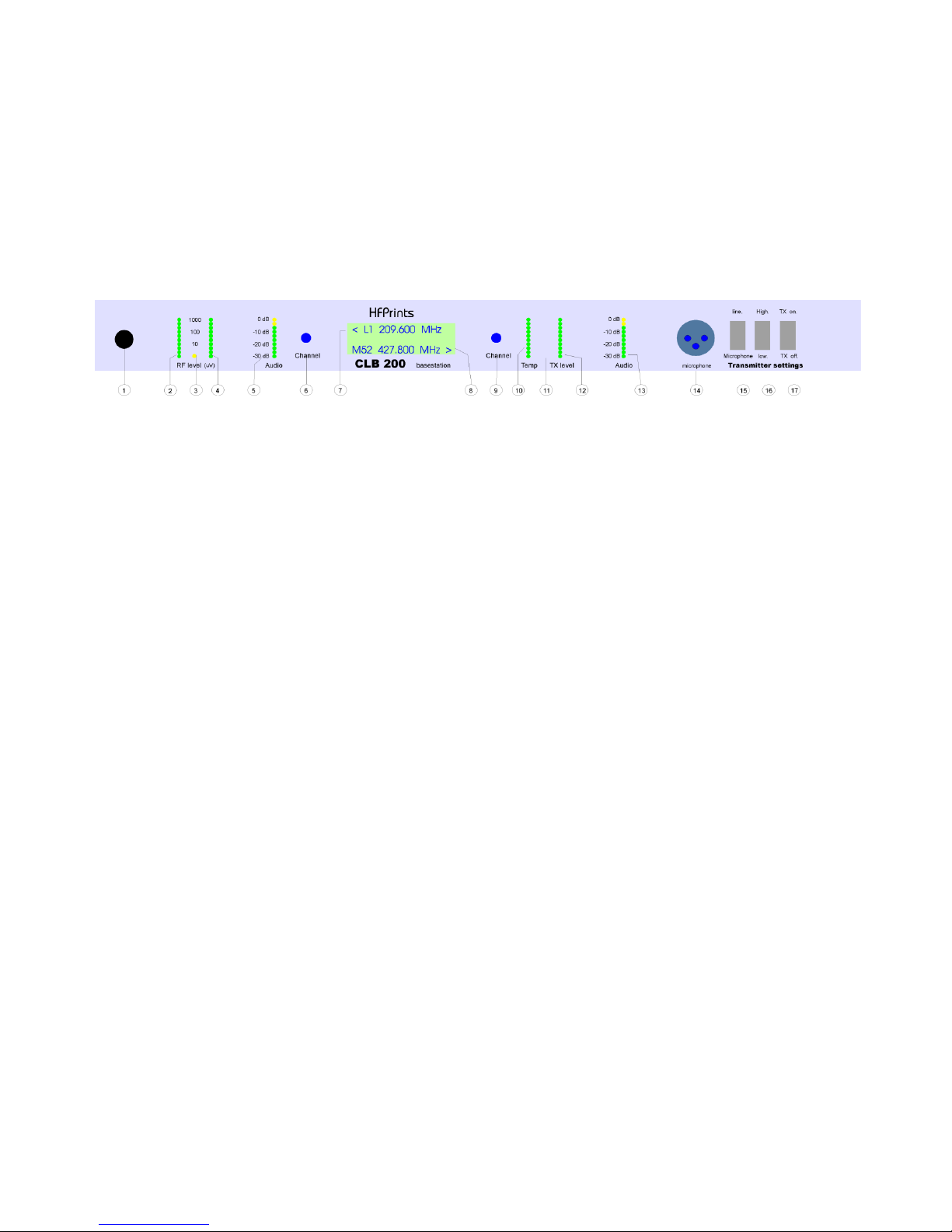
On front are several led bars and switches available including a 2 line display for frequency readout.
Drawing from the front.
1: Adjustable mute (optional).
(Standard mute by remote control port)
2 - 4 Led bar field strength indication for both receivers. Yellow LED (3) will light up when audio is present.
5: Led bar indication of audio output level. Level from -30 - 0 dB (= 6dBU)
6: Channel switch for the diversity receiver(s)
7: Display. Top line of the display shows the channel number and frequency of the VHF receiver.
8: Display. Bottom line of the display shows the channel number and frequency of the UHF transmitter.
9: Channel switch for UHF transmitter.
10: Led bar for temperature indication. CLB200 is equipped with a temperature controlled cooling fan.
11: Yellow LED lights up when the transmitter is on air.
12: LED bar indicates output level of the transmitter. This is indicative only. Low power two to four LED,
High power 8 to10 LED.
13: LED bar for transmitters audio level, both audio inputs have built in audio limiter to prevent overload / clipping.
14: Microphone input, XLR 3 connector, requires a microphone (2 - 5 mV dynamic).
15: Selection switch between Line in (rear) and microphone (front)
16: Selection switches between high and low transmitting power.
17: Selection between transmitter "standby" or transmitter "on air".

Operation:
Receiver:
Left channel switch controls the receiver frequency. Frequency can be read on the top line of the display. With an
optional adjustable mute, mute level can be controlled. If a remote control is used, mute can be controlled by the
remote. In remote control mode, left channel switch is overruled by the remote control.
Transmitter (only for CLB200WB):
Right channel switch controls the transmitter’s frequency. Frequency can be read on the bottom line of the display. In
remote control mode, right channel switch is overrules by the remote control. Note: channel changing can only be
done in standby mode.
Audio switch
Audio switch selects between line in (6 dBU) and microphone at the front (about 2-5 mV)
Note: Microphone level is not adjustable.
High low power
Default UHF transmitting power is 5W (high mode), changing the hi / low switch to low, transmitter has a reduced
output power. In remote control, Hi /Low can only be controlled if the Hi / low switch is in High mode.
TX on air.
This switch controls the standby and on air mode of the transmitter. In remote, switch must be in standby mode to be
able to control the transmitter. (note: transmitter must also be in standby mode before changing the transmitters
frequency)
Note to PTT.
GND is transmitting, open standby.
Notes on using remote control.
By using the remote control, several dc voltages can be read out and take external control over the receivers and
transmitter. Some functions are in parallel with switches that are located on the front panel.
CLR 200 WB (mono and stereo)
Several switches like on-off and mono-stereo are not used to prevent unwanted settings on the front panel that makes
remote control impossible.
CLB 200 WB transmitter settings:
Input selection, Microphone or Line in. Cannot be controlled by remote control.
Power, high or low, High Cannot be controlled by the remote control.
TX on / standby mode, Can be controlled by the remote control.
If the transmitter is turned on using the front, the transmitter is turned on, regardless of the remote control.

Power of the CLB 200 WB:
The CLB has a standard 230V power supply. For use in cars, planes etc. where no 230V is present
CLB 200 can be provided with a 12V connector. This is a 4-pin XLR connector.
12V Input and 230V secondary output are not parallel, YOU CAN NOT recharge a battery this way.
Cooling the CLB 200 (installation instructions).
The CLB produces very little heat. In a situation where the CLB is rack mounted and external heat (heat stress of
other equipment) the unit be overheated. In a case of overheating, a temperature controlled fan will cool down the
internal temperature. The internal temperature can be read from led bar on the front panel that indicates the internal
temperature. (read out on lead bar is for indication only)
The internal fan takes fresh air from slides in the right-hand side of the enclosure that flows along the power supply
and the rest of the electronics. The hot air exits at the left side of the enclosure. On both sides should be space where
air can flow without any obstructions (Usually, there is a 2cm space in mounting racks, what is sufficient. The entire
system is calculated to handle an internal temperature of 60 degrees C.)
Remote control.
The CLB includes a remote control controller.
Remote controls are designed in many shapes and functionalities, depending on client’s wishes.
By default, there is a 25 pin Sub D connector available, pinning see page 22)
The operation of the transmitter is parallel to the front switches. TX Standby / on air can be controlled.
Note on channel selection from the transmitter.
The UHF transmitter module can be extended with an extra receiver that operates at the same frequency.
Activating the PTT contact, the transmitter will receive new data. The UHF transmitter’s PLL will shift slightly to avoid
interference in the extra UHF receiver module. Frequency changes while transmitting will only be active at the moment
that the PTT contact reactivates. Read: only in standby frequencies can be changed.
HiDyn.
CLB200 features a broadband receiving system that is compatible with Sennheiser HiDyn. Other brands also use this
system that is called HiDyn. HiDyn is an audio compression technique (2: 1) on the transmitter side, an audio
expansion technique (1: 2) on the receive side. This gives additional signal noise ratio.
CLR 200 dual:
CLR 200 Dual has two dual receivers that usually operate on its own frequency. If both receivers are set to the same
frequency for test purposes it can generate a noise sound on the output. This is caused by a low crosstalk between
the two oscillators. Because the receivers are never used on the same frequencies, this will not occur, but we have to
mention it to avoid it to occur.
Selecting audio from the Reporter transmitter. Special for the France market we can switch the audio to “Line out” for
the normal program to the second audio out for talkback options.

Specifications CLB 200 WB reporter base station
General:
Power supply 230V 40VA 12 - 15V 2.5A
Antenna connectors N optional BNC - TNC
Audio connector (s) XLR 3 male / female
Dimensions 1U 19 "depth 280mm
Transmitter
Number of channels: 16 adjustable at front
Frequency range standard (narrowband) 410-470 MHz bands 415-430 440-470
Switching bandwidth > 15 MHz
PLL Frequency Step 12.5 to 25 or 100 kHz programmable
Channel switching BCD switch,
RF power ledbar 10 led
Temperature ledbar 10 led
Audio input ledbar 10 led = 30dB audio
Range audio ledbar -24 - + 6dBm
PTT front or via remote = parallel
RF + audio specifications
RF power 5 Watt switchable 5 or 1 Watt
Frequency modulation (standard) 3 kHz peak
Line input signal audio 6 dBm symmetric
De-emphases 750 us
Distortion 0,5 % typical
Signal noise > 45 dB (300 Hz –3 kHz unweight)
Audio frequency range (standard) 200 Hz –3 kHz Flat within +/- 1 dB
Receiver
Number of channels 16 adjustable via front
Frequency range VHF 174 - 230 MHz
UHF 556 –606 MHz
Switching band width > 50 MHz
Frequency step 25 –100 kHz programmable.
IF 1eIF 125 MHz 2e IF 10,7 MHz
IF band width 180 kHz
Antenna connection N 2x diversity
Audio connections XLR
Led bar 10 led 2x RF 1 uV - 1000 uV
10 led audio -24 / + 6dBm
Mute signaling led internal adjust, extern via remote
RF + audio specifications
Sensitivity for 20dB Sinad < 1,0 uV typical 0,7 uV
Image rejection > 70 dB typ.
Blocking 50 MHz > 80 dB
Spurious > 76 dB typical > 80 dB
IM 3e> 76 dB typical > 80 dB
Input IP3 > 6 dBm typical > 10 dBm
Audio output level 0 dBm a-symmetric non floating
6 dBm symmetric non floating
De-emphases 50 us
Distortion 0,5 % typical 0,7 % max
Audio 20 Hz –15 kHz mono +/- 1 dB
mono signal to noise versus field strength (Typical) HD=HIDYN
HF signal 2 uV 40 dB 70 dB
10 uV 54 dB 90 dB
100uV >60 dB 90 dB

Programming the entire unit:
Connect a laptop with RS232 adapter cable to connect the program to the interface board.
(Interface Print the front print, connection behind the unit (next antenna connector) via a 3.5mm jack)
Open the HyperTerminal program. (desk accessories), or use eq. Program.
Settings:
Port: COM1 ?? depending on the PC
Bits per second 9600
Data Bits 8
Paritity no
Stop bit 1
Flow control no
The settings for communications made now.
Reading memory button P
Channel Change key line number than channel name
Change frequency key line number than frequency

Remote pin configuration of the CLB 200 W. (French version)
standard description I / O remarks
pin number
1 Ground O
2 +5V O
3 reporter talkback select out O for France only
4** TX signalizing O +5V = TX on
5** NC
6** TX contact (PTT) I GND is TX on open is front control
7** RF output level (TX) O 0 –5V load >1k
8** temperature indication O 0 –5V load >1k
9** internal / external select TX I GND is extern open = internal
10** TX channel bit 4 I GND = 0 open = 1
11** TX channel bit 3 I GND = 0 open = 1
12** TX channel bit 2 I GND = 0 open = 1
13** TX channel bit 1 I GND = 0 open = 1
14 +5V O
15 reporter talkback select out O for France only
16 Mute / audio led O 0V = mute > 5V = audio
17 audio level O 0 –5V load > 1k
18 Mute control RX I 0 –5V adjustable voltage
19 field strength B O 0 –5V load >1k
20 field strength A O 0 –5V load >1k
21 internal / external select RX I GND is extern open = internal
22 RX channel bit 4 I GND = 0 open = 1
23 RX channel bit 3 I GND = 0 open = 1
25 RX channel bit 2 I GND = 0 open = 1
25 RX channel bit 1 I GND = 0 open = 1
Note Mute setting via remote.
0V (GND) audio
5V maximum mute threshold, about 50 uV
In between all levels adjustable.
*PTT GND pin 6 to Ground, is parallel to the front switch. On remote PTT, front switch off.
** CLB 200 only not at CLR
I/O I = in O = out
I if possible open collector control.
GND is ground

Remote pin configuration of the CLR 200-W dual receiver .
standard description I / O remarks
pin number
1 Ground O
2 +5V O
3 reporter talkback select out O for France only
4 RX2 Mute / audio led O 0V = mute > 5V = audio
5 RX2 audio level O 0 –5V load > 1k
6 NC
7 RX2 field strength B O 0 –5V load >1k
8 RX2 field strength A O 0 –5V load >1k
9 RX2 internal / external select RX I GND is extern open = intern
10 RX2 RX channel bit 4 I GND = 0 open = 1
11 RX2 RX channel bit 3 I GND = 0 open = 1
12 RX2 RX channel bit 2 I GND = 0 open = 1
13 RX2 RX channel bit 1 I GND = 0 open = 1
14 +5V O
15 RX1 reporter talkback select out O for France only
16 RX1 Mute / audio led O 0V = mute > 5V = audio
17 RX1 audio level O 0 –5V load > 1k
18 RX1 Mute control RX I 0 –5V adjustable voltage
19 RX1 field strength B O 0 –5V load >1k
20 RX1 field strength A O 0 –5V load >1k
21 RX1 internal / external select RX I GND is extern open = internal
22 RX1 RX channel bit 4 I GND = 0 open = 1
23 RX1 RX channel bit 3 I GND = 0 open = 1
25 RX1 RX channel bit 2 I GND = 0 open = 1
25 RX1 RX channel bit 1 I GND = 0 open = 1
Note Mute setting via remote.
0V (GND) audio
5V maximum mute threshold, about 50 uV
In between all levels adjustable.
I/O I = in O = out
I if possible open collector control.
.
H.F.Prints
Overcinge 40
8226 TN Lelystad
0320-250487
www.hfprints.com
This manual suits for next models
1
Table of contents


