Hütter PRO300 User manual

Hütter Safety International
1
EN 795 TYPE B
BEAM ANCHOR PRO 300-450-600 / PUNTO DE ANCLAJE MÓVIL PRO 300-450-600
HANDLEIDING VOOR GEBRUIK EN ONDERHOUD
OPERATING INSTRUCTIONS
MANUAL DE INSTRUCCIONES Y MANTENIMIENTO
HÜTTER SAFETY INTERNATIONAL B.V.
Kruisweg 763, 2132 NG Hoofddorp, The Netherlands
TEL +31 (0)20 - 6533400 | info@hutter.nl | www.hutter.nl
v.2.0
USER MANUAL
SLIDING BEAM ANCHOR PRO300 / PRO450 / PRO600
PUNTO DE ANCLAJE MÓVIL PRO300 / PRO450 / PRO600


Hütter Safety International
3
MERKTEKEN / LABELLING / MARCACIÓN
EN795:2013 15kN 1x pers.

Hütter Safety International
4
Warning!:
This product is to be used as part of a personal fall protection system. The user must read the manufacturer’s instruction and be familiar with each component of the
equipment. The user must fully understand this instruction and to be trained before using this equipment. This equipment should not be used for material lifting or any
other use other than a fall protection system. This product is intended for one person using. Any alteration and misuse of this equipment, or failure to follow instructions,
may result in serious injury or death.
IMPORTANT: lf you have questions on the use, care, installation or suitability of this Dual Beam Trolley Anchor · for your application, please contact your dealers,
distributors, or manufacturer for a guide.
DUAL BEAM TROLLEY ANCHOR COMPONENTS: DUAL BEAM TROLLEY ANCHOR COMPONENTS:
SPECI FICATIONS
DIMENSIONS
Beam Size Range: 12-in. (305mm) Maximum
2.5-in. (63.5mm) Minimum
18-in. (457mm) Maximum
2.5-in. (63.5mm) Minimum
24-in. (610mm) Maximum
2.5-in. (63.5mm) Minimum
Flange Thickness : 1.S-in.(38mm) Maximum
Purpose:
The Dual Beam Trolley Anchor is used as an anchorage connector for a personal fall arrest system. lt’s designed to be attached on the Horizontal 1-Beam. The Dual Beam
Trolley Anchor might be used as an end termination for either. a shock-absorbing lanyard or self-retracting lifeline for fall arrest, or with a positioning lanyard for fall
restraint.
Limitations:
• Beam Flange Sizes: The Dual Beam Trolley Anchor may only be installed on beams with flanges within the adjustment range of the model. See the SPECIFICATION.
• capacity: This Dual Beam Trolley Anchor is designed for one person use with a combined weight (clothing, tools, etc.) of no more than 310 Ibs (140kgs).
No more than one personal protective system may be connected to this equipment at one time.
• Free Fall: Personal fall arrest systems used with this equipment must be rigged to limit the free fall to a maximum of 6 feet. The maximum free fall must always
be within the manufacturer’s free fall capacity of the system components used to arrest the fall. When a free fall greater than 6 feet and up to a maximum of 12
feet if possible, Hütter Safety recommends using a personal fall arrest system incorporating with an energy absorbing lanyard.
• Trolley Load Angle: Leads imposed on the Dual Beam Trolley Anchor by the personal fall arrest system must remain within 30 degrees of the vertical center line
of the beam.
• Swing Faits: Before installing or using, make consideration for eliminating or minimizing all swing fall hazards. Swing
falls occur when the anchor is not directly above the location where a fall occurs. The user must always work as close
to be in line with the anchor point as possible. Swing falls significantly increase the possibility of serious injury or death
in the event of a fall.
EN
1 Trolley Clamp 6 Positioning ratchet for Lock Pin
2 Trolley Wheel with Ball Bearing 7 Safety Lock
3 Nylon Nut 8 Quick release Lock Pin
4 Hexagonal Rod 9 D-ring Hanger
5 End Screw w/Nylon Nut 10 D-ring
MATERIALS:
All materials used in the construction of this equipment are as follows:
• Stainless Steel
• Anodized Alloy Aluminum
• Plated Alloy Steel
WEIGHT:
Pro 300: 6.61 LB(3.00KG)
Pro 450 : 7.23LB{3.28KG)
Pro 600: 7.8SLB{3.56KG)

Hütter Safety International
5
EN
• Fall Clearance: There must be sufficient clearance below the anchorage connector
to arrest a fall before the user strikes the ground or other obstruction.
The clearance required is dependent on the following safety factors:
+ Elevation of Dual Beam Trolley Anchor
+ Length of connecting subsystem
+ Deceleration distance
+ Movement of harness attachment element
+ Worker height
+ Free fall distance
Personal Fall Arrest System: The Dual Beam Trolley Anchor is designed for use with Hütter
Safety approved components or CE/ANSI certified components. Use of this
equipment with non-approved components may result in incompatibility between equip-
ment , and could affect the reliability and safety of the complete system. A full body
harness must be worn by the user when connected to the Dual Beam Trolley Anchor. When making connections with the Dual Beam Trolley Anchor, eliminate all possibility
of roll-out. Roll-out occurs when interference between a hook and the attachment point causes the hook gate to unintentionally open and release. All connector gates must
be self-closing and self-locking.
INSTALLATION AND USE
lnspect the equipment according to INSPECTION of this manual before each use.
The Dual Beam Trolley Anchor could only be installed on any 1-beam for horizontal position, and located on the bottom of the 1-beam.
Step 1. Remove the quick release loek pins. Then press the safety loek to adjust the trolley clamps.
Step 2. Place the Dual Beam Trolley Anchor onto beam flange on the bottom position of the 1-beam.
Step 3. Place trolley clamp against one side of the beam flange. Slide the other trolley clamp against
opposite side of the beam flange. Ensure the D-ring is at the middle position of the I-beam.
Step 4. Ensure the safety loek is in nearest position to the beam flange.
Step 5. lnsert the quick release loek pins to fix the safety locks, ensuring pins are locked into place.
Step 6. Ensure the quick release loek pins have not bottomed out. lf quick release pins have bottomed out,
reinstall the trolley clamp to the next locking position. lf the quick release loek pin is damaged or absent, the equipment is still in a workable condition. However for safety
concerning, when one of the quick release loek pins is damaged or absent, the equipment must be sent back to your dealers, distributors, or manufacturer to replace a new
quick release loek pin.

Hütter Safety International
6
EN
TRAINING
lt is the responsibility of the users to assure that they are familiar with the instructions, and are trained in the correct care and use of this equipment. Users must also be
aware of the operating characteristics, application limits, and the consequences of improper use of this equipment.
INSPECTION
Frequency:
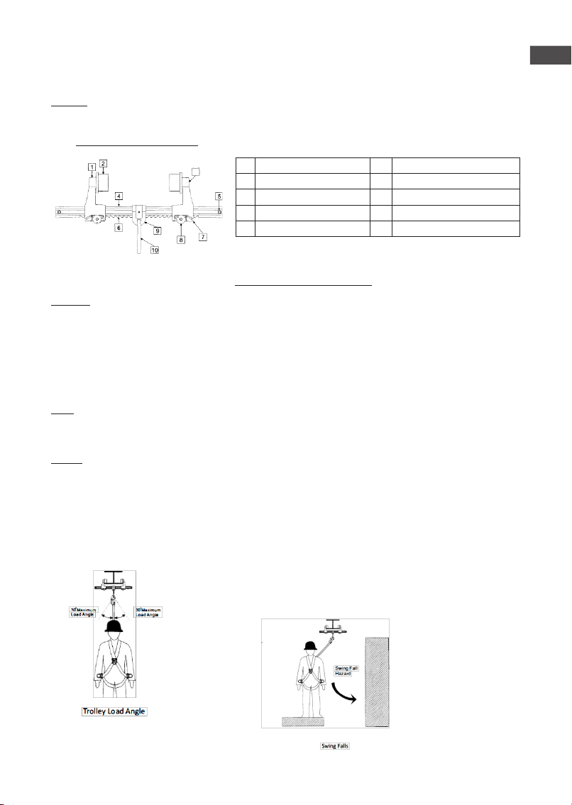
Before each use, inspect the Dual Beam Trolley Anchor according to following steps and see DUAL BEAM TROLLEY ANCHOR COMPONENTS for part identification. The Dual
Beam Trolley Anchor must be formally inspected by a competent person other than the user at least annually. Record the results in
INSPECTION AND MAINTENANCE LOG.
lnspection Steps:
Step 1.lnspect Dual Beam Trolley Anchor for damage: Look for cracks, dents, or deformities. Look for bending or wear on the hexagonal rod, trolley
clamps, safety loek, quick release loek pin, and trolley wheels. Ensure no parts are missing.
Step 2. lnspect entire unit for excessive corrosion.
Step 3. Ensure the quick release loek pin can be inserted through the hole on safety loek button, and locks in place.
Step 4. Record the inspection date and results in the INSPECTION AND MAINTENANCE LOG.
lf inspection reveals an unsafe or detective condition, remove the equipment from service and destroy, or return to Hütter Safety for repair.
NOTE: Only Hütter Safety or porties authorized in writing are qualified to repair this equipment.
MAINTENANCE, SERVICE, STORAGE
Cleaning:
Periodically clean the Dual Beam Trolley Anchor by water and a mild soap solution. Do not use acids or other caustic chemicals that could damage the system components.
A lubricant may be applied to the safety loek button and the quick release lock pin.
Storage:
Store the equipment in a cool, dry, dark place, chemically neutra 1, away from sharp corners, sources of heat, humidity, corrosive substances or other damaging conditions.
VERIFICATION PROCEDURE:
Service life of the product is 10 years (in accordance with the annual examination by a competent person authorized by Hütter Safety),
although its actual service life may be longer or shorter, depending on its usage and/or annual inspection results.
Hütter Safety or his authorised representative must systematically check the beam anchor in case of doubt or after a fall and at least every
year by, to guarantee its state and thus the safety of the end-user.
The product data sheet should be completed after each annual product verification.
SERVICING AND STORAGE: (Comply strictly with these instructions)
During transport, keep the beam anchor in its packaging, away from any cutting surface. Wipe it with a rag and place it in a well-ventilated location, let
it dry naturally and keep it away from a flame or heat source. The beam anchor should be stored in its packaging in a warm, dry, ventilated place, away
from chemicals.
INSPECTION AND MAINTENANCE LOG
Company: Location : Date Purchased:
Serial Noº : Model Noº :
Year Date By a Qualified Person No missing parts No corrosion No Deformation Functioning condition No changes to
Attachment structure
Corrective Action Maintenance
Performed
Corrective Action Maintenance
Performed
Corrective Action Maintenance
Performed

SERIAL NUMBER:
MODEL NUMBER:
DATE OF PURCHASE: DATE OF FIRST USE:
INSPECTION DATE OBSERVATIONS OF
INSPECTION
MEDIDAS CORRECTIVAS PERFORMED MAINTENANCE
Approved by:
Approved by:
Approved by:
Approved by:
Approved by:
Approved by:
Approved by:
Approved by:
Approved by:
Approved by:
Approved by:
Approved by:
Approved by:
Approved by:
Approved by:
Approved by:
Approved by:
Approved by:
Hütter Safety International
7

EN 363
Voorbeelden van valbeveiligingssystemen / Examples of fall arrest system / Ejemplos de sistemas de detención de caídas
Eksempler på faldsikringssystemer:
EN 365
Voorbeeld van bevestigingssysteem en werkpositionering /
Example of work restraint and work positioning system /
Ejemplo de sistema de retención y posicionamiento en el trabajo
Eksempel på tilbageholdenhed og arbejde positionering:
EN795
+
EN362
+
EN358
+
EN354/EN358
EN795
+
EN362
EN795
+
EN362
EN795
+
EN362
EN795
+
EN362
EN795
+
EN362
+
Naam van de gebruiker / User’s name
Nombre del usuario
Bestelnr. / Nº ref. / Reference / Referencia :
Serienummer / Serial n° / N° de série :
Productiejaar / Date of manufacture /
Año de fabricación :
Aankoopdatum / Date of purchase / Fecha
de compra:
Datum eerste gebruik / Date of 1st use /
Fecha de la 1ª puesta en servicio:
OPMERKINGEN / COMMENTS / COMENTARIOS / KOMMENTARER:
Als onderdeel van uw risicobeoordeling moet er een noodplanworden opgemaakt voordat het werken op hoogte aanvangt
zodat adequaat op eventuele noodgevallen gereageerd kan worden.
As part of your risk assessment, you must have a rescue plan before working at height to deal with any emergency that may
arise.
Como parte de su evaluación de riesgos, debe haber implementado un plan de rescate antes de iniciar trabajos en altura
para confrontar cualquier emergencia que pueda surgir.
I tillæg til risikovurderingen du får brug for en redningsplan, før alt arbejde i højden for at opfylde en nødsituatio
EN341 // EN567 // EN1496 // EN1498 // EN1865 // EN12272 // EN12841
Hütter Safety International
Kruisweg 763, 2132 NG Hoofddorp
The Netherlands
Distributeur / Distributor / Distribudor
This manual suits for next models
2
Table of contents
Popular Safety Equipment manuals by other brands

VSPL
VSPL viraj SECURE FIRST SF-FBRL-2301 User instructions

Tractel
Tractel LCAD Operating and maintenance instructions

Petzl
Petzl PROGRESS ADJUST I TECHNICAL NOTICE

Werner
Werner AUTOCOIL 2 User instructions

Capital Safety
Capital Safety DBI SALA PROTECTA EN361 Instructions for use and maintenance

NSSL
NSSL Start Right Safety Device installation manual