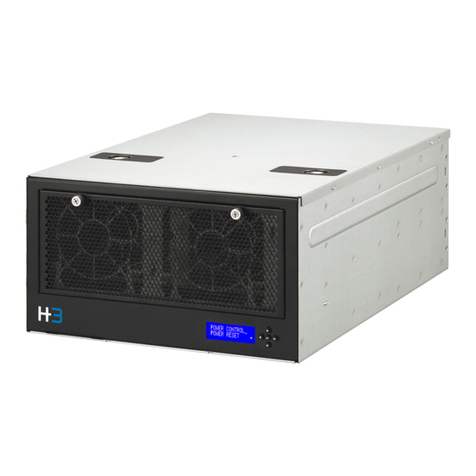
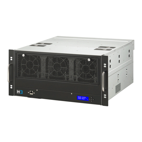
H3 Falcon PCIe User manual

Version 1.0
February 20th , 2022
Falcon PCIe Expansion Solution
User Manual
◼Falcon 4109
◼Falcon 4118

© 2022 H3 Platform Inc. or its subsidiaries. All rights reserved.H3 Platform and other trademarks are trademarks of H3 Platform
Inc. or its subsidiaries. Other trademarks may be trademarks of their respective owners.
Dear Users
Thank you for choosing our product.
The excellent quality and performance make our products superior in the like
product. For you to have the good understanding to Falcon Composable PCIe
Expansion Solutions, please read the user manual and operate according to
the suggested steps for each feature.
If you have any questions when using our machine, please feel free to contact
us. We are more than happy to serve you constantly.
Technical Support: [email protected]m
FAQ: https://www.h3platform.com/
H3 Platform Inc. researches and develops PCIe switch-based technology
and solutions.
---- H3 Platform Inc.

© 2022 H3 Platform Inc. or its subsidiaries. All rights reserved.H3 Platform and other trademarks are trademarks of H3 Platform
Inc. or its subsidiaries. Other trademarks may be trademarks of their respective owners.
Notes, Cautions, and Warning
Note
A NOTE indicates important information that helps you make better use of your
product.
Caution
A CAUTION indicates either potential damage to hardware or loss of data and tells
you how to avoid the problem.
Warning
A WARNING indicates a potential for property damage, personal injury, or death.

Table of Contents
1. Introduction ..............................................................................................................................................2
1.1 Key Features............................................................................................................................................ 2
1.2 System Modes ........................................................................................................................................ 2
2. Technical Specification...........................................................................................................................3
2.1 Chassis ..................................................................................................................................................... 3
Falcon 4109 ............................................................................................................................................ 3
Falcon 4118 ............................................................................................................................................ 3
2.2 Accessories.............................................................................................................................................. 4
External Cable ........................................................................................................................................ 4
PSU........................................................................................................................................................... 4
Host Adapter........................................................................................................................................... 4
2.3 Compatible Devices................................................................................................................................ 6
3. Requirements...........................................................................................................................................7
3.1 CPU............................................................................................................................................................ 7
3.2 Host OS..................................................................................................................................................... 7
3.3 BIOS........................................................................................................................................................... 7
3.4 Web Browsers ......................................................................................................................................... 7
4. Graphical User Interface.........................................................................................................................8
4.1 Log-In ........................................................................................................................................................ 8
4.2 Functions.................................................................................................................................................. 8
4.2.1 Overview ........................................................................................................................................ 9
4.2.2 Resource Management............................................................................................................13
4.2.3 Port Configuration .....................................................................................................................17
4.2.4 Monitor.........................................................................................................................................20
4.2.5 System Health............................................................................................................................22
4.2.6 Chassis ........................................................................................................................................25
4.2.7 Maintenance...............................................................................................................................25
4.2.8 Event Logs...................................................................................................................................27
4.2.9 Setting..........................................................................................................................................28
5. LCD ......................................................................................................................................................... 36
5.1 Operation................................................................................................................................................36
5.2 Menu .......................................................................................................................................................37
5.2.1 Power control .............................................................................................................................38
5.2.2 Power reset.................................................................................................................................38

5.2.3 System.........................................................................................................................................38
5.2.4 Slot................................................................................................................................................39
5.2.5 Devices.........................................................................................................................................39
5.2.6 Hosts............................................................................................................................................40
5.2.7 Health...........................................................................................................................................40
5.2.8 Temperature ...............................................................................................................................41
5.2.9 Network .......................................................................................................................................42
5.2.10 Reset to default .......................................................................................................................42
6. Part Replacement................................................................................................................................. 43
6.1 Fans.........................................................................................................................................................43
6.2 Power Supply Unit ................................................................................................................................43
7. Operational Safety ................................................................................................................................ 44
8. Trouble Shooting................................................................................................................................... 45
PCIe out of resource ...................................................................................................................................45
GPU P2P underperforming........................................................................................................................46
PCIe link health error...................................................................................................................................46
Failure to assign/remove a device ...........................................................................................................47
Information does not display properly on GUI.......................................................................................48
Failure to access GUI..................................................................................................................................48
Device Link Down ........................................................................................................................................48
Host Link Down............................................................................................................................................49

1

2
1. Introduction
1.1 Key Features
▪PCIe device composability
▪Device surprise-add and remove
▪PCIe port configuration
▪Real-time cluster topology
▪System performance monitoring
▪Role-based authentication and access control
1.2 System Modes
There are two system modes for Falcon PCIe Expansion solutions. The Standard mode is limited to single
host connection and does not support device dynamic allocation or host port bifurcation. The Advanced
mode supports multiple host connection and could allocated devices to hosts dynamically. You could
activate the Advanced mode with Premium License.
Please contact sales@h3platform.com for license purchase.
Standard mode
Advanced mode
▪System monitor
▪Power control from GUI
▪Download system performance data from GUI
▪Firmware update
▪User management
▪Limited to single host
▪System monitor
▪Power control from GUI
▪Download system performance data from GUI
▪Firmware update
▪User management
▪Multiple host
▪Device hot plug (OS has to support)
▪Port configuration (bifurcation)
▪Device dynamic allocation
▪Mode switch
Advanced mode requires following host BIOS setting:
Host BIOS → Advanced → PCIe/PCI/PnP configuration
▪Enable 4G decode
▪Set MMIOHBase to 56T (if possible)
▪Set MMIO High Size to 512G or higher (if possible)

3
2. Technical Specification
2.1 Chassis
Falcon 4109
Model
Falcon 4109
BMC/mCPU
Aspeed AST2500
PCIe Switch
PEX 88096; PCIe 4.0
PCIe Slots
8x PCIe4.0 x8 FHFL and 1x PCIe 4.0x16 FHFL
Slot Power
75 W, slot 1,2,7 and 8 supports +225W PCIe 8 pin power
Host Interface
SFF-8644 connectors
Fan
4x 120x120x38mm; 6700 RPM; hot swap
Operating Temp.
0°C ~ 35°C (32°F ~ 95°F)
Dimension
174(H) x 320(W) x 466(D) mm
Weight
12.75 Kg
Falcon 4118
Model
Falcon 4118
BMC/mCPU
Aspeed AST2500
PCIe Switch
PEX 88096; PCIe 4.0
PCIe Slots
16x PCIe4.0 x8 FHFL and 2x PCIe 4.0x16 low-profile
Slot Power
75 W, slot 1,2,7 and 8 (both drawers) supports +225W PCIe 8 pin power.
Host Interface
SFF-8644 connectors
Fan
6x 120x120x38mm; 6700 RPM; hot swap
Operating Temp.
0°C ~ 35°C (32°F ~ 95°F)
Dimension
5U; 219(H) x 435(W) x 450(D) mm
Weight
21.7 Kg

4
2.2 Accessories
External Cable
Interface
Mini-SAS HD
Connector
SFF-8644 to SFF-8644
Bandwidth
PCIe Gen4 x4 (per cable)
Type
Copper
Length
2m
PSU
PSU
1200 W
AC Input
100-127V
200-240V
100-240V
DC Output
+12V
+12Vsb
82A
98A
2.1A
Efficiency
94% at full load
Lifespan
250,000+ hrs.
Operating Env.
0°C ~ 56°C
85% relative humidity (non-condensing)
80 PLUS Certified
Platinum
Host Adapter
Form factor
PCIe Low-profile; MD2; PCIe 4.0 x16
Connector
Quad SFF-8644
PCIe switch
PEX 88032; PCIe 4.0
Dimension
160(L) x 68(H) mm

5
Host Adapter Guide:
Image 1 Image 2
⚫LED Signals
LED No.
Component
Signal indication
1
SFF-8644 connector 0
Good
Incorrect
No connection
2
PCIe link speed
PCIe Gen 4
PCIe Gen 3
3,4,5
Port configuration
3
4
5
Config.
1 x16 lanes
2 x8 lanes
4 x4 lanes
6
SFF-8644 connector 1
See LED 1 signal indication.
7
PCIe Switch Status
Good
Error
8
SFF-8644 connector 2
See LED 1 signal indication.
9
SFF-8644 connector 3
See LED 1 signal indication.
1. SFF-8644 connectors
2. Connection LED
3. PCIe link LED
4. Heartbeat LED
5. Jumpers
Each jumper has 3 pins. Please pay attention to the labels on PCB,
▽
sign indicates pin 1.
Image 1 illustrates pin number. Image 2 illustrates the setting for [Pin 1, 2]

6
⚫Jumpers
Jumper
Function
Setting
J5
Reserved Jumper
--
J7, J8
PCIe bifurcation
J7
J8
Config.
Pin 1, 2
Pin 1, 2
1 x16 lanes
Pin 2, 3
Pin 2, 3
2 x8 lanes
Pin 1, 2
Pin 2, 3
4 x4 lanes
J9
Mode
J9
Config.
Pin 1, 2
Host mode
Pin 2, 3
Target mode
2.3 Compatible Devices
Devices
Accelerator
▪Nvidia A10
▪Nvidia RTX A4000
Storage
▪Intel® P4500, P4600, P4800X
▪Samsung PM1725a, PM1725b, PM1733, PM1735
NIC
▪Mellanox ConnectX®-4, ConnectX®-5, ConnectX®-6
Devices listed above are devices that have been tested. Standard PCIe devices may also be compatible.
If you can’t find your device on the list or is planning to use our products with special PCIe device, please contact
[email protected] for help.

7
3. Requirements
3.1 CPU
3.2 Host OS
3.3 BIOS
3.4 Web Browsers
Intel
Xeon E5 V3 family or later.
AMD
EPYC 7001 series or later.
Standard Mode
Advanced mode
Ubuntu
No limitations
16.04 LTS, 18.04 LTS, 20.04 LTS
Windows
Build 1903-20H2
Cent OS / RHEL
7.3-8.0
Host BIOS Capability
▪4G decode
▪MMIOBase > 56T
▪MMIO High size >512G
▪PCI Access Control Services (ACS) disability.
Mozilla Firefox
Please update to the latest version.
Google Chrome
Please update to the latest version.
Advanced mode is not limited to the OS listed above. The listed OS are recommended as they have been tested to
support PCIe device hot plug.
Also requires a vacant PCIe x16 slot on the host server for host adapter card installation. (PCIe Gen3 or later)
Enabling ACS may impact GUP P2P support.
However, it does not affect the operation of Falcon
PCIe Expansion solutions.

8
4. Graphical User Interface
4.1 Log-In
Every time you access the GUI, you will be asked to log in.
Please enter your Username and Password.
4.2 Functions
The menu at the top (or top-left corner) of the page shows all the available functions.
Please find details of each function in the relative section.

9
4.2.1 Overview
The Overview page sorts out the basic performance data of the Falcon PCIe Expansion system.
Resource List
The Resource List provides PCIe device usage and host port usage information.
Usage of specific device types (GPU, NVMe SSD, FPGA and NIC) features can be accessed with Premium
License activated.
“Used” indicates the number of devices that are currently assigned to hosts.
e.g. Used 2 of 10.
There are 10 devices installed in Falcon system, 2 of them are assigned to the host(s).

10
GPU Utilization Rate(%)
In the GPU utilization chart, users can check the GPU utilization of a specific GPU in a specific period. Y-axis
represents the utilization rate and X-axis represents a specific GPU. The data is read from PCIe devices
directly, only the compatible devices with the out-band information will be shown here.
1. Graph title:
GPU Utilization Rate (%)
2. Utilization rate:
The average GPU utilization, scaled from 0~100%.
3. Bar graph:
Utilization rate of the GPUs, displayed in bar graphs.
4. Device number:
Displayed as [Drawer #]:[slot#]. E.g., 1:1 represents device on slot 1 of drawer 1
5. Display period:
The graph will display the utilization rate of the GPUs in the past
hours. (1-, 12-, 24-, or 72-hours options available)
6. Download:
Download the GPU utilization data (up to the past 72 hours)
PCIe Throughput (MB/s)
Only shows the utilization rate of GPU devices.

11
1. Graph title:
PCIe Throughput (MB/s)
2. Throughput rate:
The numbers on throughput rate scale (MB/s) will change as throughput changes.
3. Time:
The X-axis display system times. (per hour)
4. Devices:
List all the devices installed. Every device has a unique color indicator.
5. Throughput curve:
The curve of PCIe throughput of each device, distinguished by the color.
6. List down menu:
Displays throughput of each device at a specific time point.
Move the mouse over the curve to see this menu.
7. Traffics:
Select traffic types to display on the throughput graph.
There are three types: Ingress, Egress, and Sum.
8. Display period:
The graph will display the throughput rate of the devices in the past
hours. (1, 12, 24, or 72-hours options available)
9. Download:
Download the PCIe throughput data. (Up to the past 72 hours)
PCIe Link Health
1. Graph title:
PCIe Link Health
2. Health status:
Green=healthy, Red=error, Gray=no link.
3. Port #:
PCIe port number.
4. Port type:
Indicates whether the PCIe port is a device port or host port.
5. Device name:
The name of the device linked to the PCIe port.

12
Thermal
Displays the average temperature of each component (in °C) in the Falcon PCIe chassis is displayed.
Green = good, Amber = moderate, Red = overheat
System Profile
The System Profile displays basic system information of the machine.
Model:
Chassis model name.
Serial number:
Serial number of this machine.
Mac address:
Mac address of this machine.
Firmware:
BMC firmware version.
System up time:
Time since the system is powered-on.
Last login:
The last user.
Last login time:
The time of last login
Online user:
The number of users currently online.
IP address:
The IP address of this machine.
Falcon System will shut down automatically when the system detects any
device temperature >85°C for over 10 seconds.
This temperature threshold is adjustable, please see Advanced Config →
Thermal Control for more detail.
4118

13
4.2.2 Resource Management
There are two tabs under Resource Management, Topology and List. The topology view shows the graph of
hosts, devices, and PCIe switch. The list view lists all the devices and hosts in a table.
Topology View
1. Display mode:
Select Topology or List view for resource management.
2. Allocate:
This button is used when allocating resources. (See Device Allocation section for detail)
3. Drawer 1 PCIe ports:
PCIe ports topology of drawer 1.
4. Drawer 2 PCIe ports:
PCIe ports topology of drawer 2. (Falcon 4118)
5. System mode:
Displays the current system mode of the drawer.
6. Refresh:
Refresh the topology display.
7. Legends:
Help users to identify components in the topology view.
8. Port label:
Port label diagram that helps users to identify PCIe ports.
Device provisioning can only be done under Topology tab.

14
⚫Port Information
List View
1. Slot #:
This column shows the slot number.
2. Status:
The status of the device.
3. Assigned host:
The host that the device is assigned to.
4. Device Name:
Model name of the device
5. Device type:
The type of the device. (GPU, NVMe SSD, FPGA, NIC…)
6. Temperature:
The temperature of the device.
7. Link capability:
Link capability of the device / Link capability of the PCIe slot.
Displayed in [PCIe generation x lanes]
8. Device details:
Click on the drop-down icon to show detailed information of the device.
9. Refresh:
Click to refresh the list.
10. Port label:
Port label diagram that helps users to identify PCIe ports.
1. Color tag:
Indicates which host that the device is assigned too. The color is corresponding to the color frame of
host port. (E.g., the device is assigned to 1:H1, color=Blue)
2. Port & device:
Port number and device name.
The data is read from PCIe devices directly, only available if the device provides the out-band information.

15
Assign Devices
Device allocation is only enabled in Advance mode.
Select Topology view to assign devices.
Confirmation window will pop-up. Click “Yes” to proceed. Then Click “OK” to finish the process.
1. Select the host.
2. Select the available device.
3. Click “Allocate” to assign.
Users could select multiple devices at a time for batch assignment.
The link icon and color tag should appear when the device is successfully assigned.
Table of contents
Other H3 Computer Hardware manuals
Popular Computer Hardware manuals by other brands

Kodak
Kodak Digital Science 4800 user guide

Hynix Semiconductor
Hynix Semiconductor GMS81508A user manual

LS Industrial Systems
LS Industrial Systems SV-iS7 PLC user manual

HighPoint
HighPoint RR3700 Series installation guide

Linear Technology
Linear Technology DC1307A Demo Manual

Joranalogue
Joranalogue DELAY 1 quick start guide

Silver Monkey
Silver Monkey Stormy 120 mm user manual

Renesas
Renesas Converter Board M3T-FLX-42SPB user manual

Panasonic
Panasonic 2SC1473 Specification sheet

National Instruments
National Instruments BNC-208 Series user manual

Hypertec
Hypertec HyperNet HYNTR70002 user guide

Epson
Epson S5U13C00M00C100 user manual