H3C S12500R Series Application guide

H3C S12500R Switch Router Series
Hardware Reference
New H3C Technologies Co., Ltd.
http://www.h3c.com
Document version: 6W101-20201015

Copyright © 2020, New H3C Technologies Co., Ltd. and its licensors
All rights reserved
No part of this manual may be reproduced or transmitted in any form or by any means without prior written
consent of New H3C Technologies Co., Ltd.
Trademarks
Except for the trademarks of New H3C Technologies Co., Ltd., any trademarks that may be mentioned in this
document are the property of their respective owners.
Notice
The information in this document is subject to change without notice. All contents in this document, including
statements, information, and recommendations, are believed to be accurate, but they are presented without
warranty of any kind, express or implied. H3C shall not be liable for technical or editorial errors or omissions
contained herein.

Preface
This document describes the hardware information of H3C S12500R switch routers, including
chassis views and technical specifications, FRUs and compatibility matrixes, LEDs, and cables.
This preface includes the following topics about the documentation:
•
Audience.
•
Conventions.
•
Documentation feedback.
Audience
This documentation is intended for:
•
Network planners.
•
Field technical support and servicing engineers.
•
Network administrators working with the S12500R switch routers.
Conventions
The following information describes the conventions used in the documentation.
Command conventions
Convention
Description
Boldface Bold text represents commands and keywords that you enter literally as shown.
Italic Italic text represents arguments that you replace with actual values.
[ ] Square brackets enclose syntax choices (keywords or arguments) that are optional.
{ x | y | ... }
Braces enclose a set of required syntax choices separated by vertical bars, from which
you select one.
[ x | y | ... ]
Square brackets enclose a set of optional syntax choices separated by vertical bars,
from which you select one or none.
{ x | y | ... } *
Asterisk marked braces enclose a set of required syntax choices separated by vertical
bars, from which you select a minimum of one.
[ x | y | ... ] *
Asterisk marked square brackets enclose optional syntaxchoices separated by vertical
bars, from which you select one choice, multiple choices, or none.
&<1-n> The argument or keyword and argument combination before the ampersand (&) sign
can be entered 1 to n times.
# A line that starts with a pound (#) sign is comments.
GUI conventions
Convention
Description
Boldface Window names, button names, field names, and menu items are in Boldface. For
example, the New User window opens; click OK.
> Multi-level menus are separated by angle brackets. For example, File > Create >
Folder.

Symbols
Convention
Description
WARNING! An alert that calls attention to important information that if not understood or followed
can result in personal injury.
CAUTION:
An alert that calls attention to important information that if not understood or followed
can result in data loss, data corruption, or damage to hardware or software.
IMPORTANT:
An alert that calls attention to essential information.
NOTE:
An alert that contains additional or supplementary information.
TIP:
An alert that provides helpful information.
Network topology icons
Convention
Description
Represents a generic network device, such as a router, switch, or firewall.
Represents a routing-capable device, such as a router or Layer 3 switch.
Represents a generic switch, such as a Layer 2 or Layer 3 switch, or a router that
supports Layer 2 forwarding and other Layer 2 features.
Represents an access controller, a unified wired-WLAN module, or the access
controller engine on a unified wired-WLAN switch.
Represents an access point.
Represents a wireless terminator unit.
Represents a wireless terminator.
Represents a mesh access point.
Represents omnidirectional signals.
Represents directional signals.
Represents a security product, such as a firewall, UTM, multiservice security
gateway, or load balancing device.
Represents a security module, such as a firewall, load balancing, NetStream, SSL
VPN, IPS, or ACG module.
Examples provided in this document
Examples in this document might use devices that differ from your device in hardware model,
configuration, or software version. It is normal that the port numbers, sample output, screenshots,
and other information in the examples differ from what you have on your device.
T
T
T
T

Documentation feedback
You can e-mail your comments about product documentation to info@h3c.com.
We appreciate your comments.

i
Contents
1 Chassis views and technical specifications··············································1-1
Chassis views·················································································································································1-1
Chassis components·······································································································································1-2
Technical specifications··································································································································1-5
Weights and dimensions·························································································································1-5
Module power consumption and system power consumption·································································1-7
Heat dissipation·······································································································································1-8
Environmental specifications···················································································································1-8
Chassis ordering information ··························································································································1-8

1-1
1 Chassis views and technical
specifications
The H3C S12500R Ethernet Switch Router Series is a set of next-generation rack switch routers
designed for data center core networks. It optimizes the CLOS switching fabric architecture and uses
the variable cell-based traffic scheduling and control forwarding mechanism to deliver higher
forwarding efficiency, more refined congestion control, and hierarchical scheduling.
Unless otherwise stated, MPUs, service modules, and fabric modules are collectively referred to as
"modules" in this document.
Chassis views
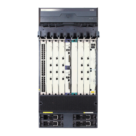
Figure 1-1 S12516R

1-2
Figure 1-2 S12508R
Figure 1-3 S12504R
Chassis components
The device has an MPU section, service module section, power module section, fan tray section,
and fabric module section. The following figure uses the S12516R for illustration.

1-3
Figure 1-4 Front and rear views of the S12516R
(1) MPU section
(2) Service module section
(3) Power module section
(4) Fan tray section
(5) Fabric module section
Table 1-1 Description for the device sections
Section Description
MPU section
•(S12516R and S12508R—Ejector levers
of the MPUs and ejector lever pillow
blocks on the MPU slots are pink marked.
The MPU slots are above the service
module slots.
•S12504R—MPU slot numbers on the
chassis and the names on the MPUs are
pink marked. The MPU slots are below
the service module slots.)
No MPUs are provided with the device. Purchase MPUs
yourself.
The device has two MPU slots. You can install one MPU,
or two MPUs for redundancy for the device. To install only
one MPU for the device, you can install it in either of the
MPU slots.
Service module section
(The edges or ejector levers of the service
modules and the ejector lever pillow blocks on
the service module slots are purple marked.)
No service modules are provided with the device.
Purchase service modules yourself.
•S12516R—16 service module slots.
•S12508R—8 service module slots.
•S12504R—4 service module slots.
You can install a service module in any of the empty
service module slots.
3
4
1
25

1-4
Section Description
Power module section
No powermodules are provided with the device. Purchase
power modules yourself.
•S12516R—16 power module slots, with eight on
each side of the chassis rear.
•S12508R—8 power module slots, with four on each
side of the chassis rear.
•S12504R—4 power module slots, with two on each
side of the chassis rear.
The device supports N+N (dual power input lines) and N+1
(single power input line) power module redundancy.
Determine the number of power modules based on power
supply mode and the system power consumption.
You can install a power module in any of the empty power
module slots.
Fan tray section
(The fan tray section is at the rear of the
chassis. Each fan tray covers three fabric
module slots.)
No fan trays are provided with the device. Purchase fan
trays yourself.
The device provides two fan tray slots FAN1 and FAN2. It
can operate correctly with one fan tray. As a best practice,
install two fan trays for the device to achieve redundancy.
Fabric module section
(Covered by the fan trays)
No fabric modules or fabric module slot filler panels are
provided with the device. Purchase fabric modules and
fabric module slot filler panels yourself.
•Configure two to six fabric modules for the device.
Install filler panels in the empty fabric module slots.
•The fabric module slots are covered by fan trays. To
replace a fabric module, remove the fan tray above it.
Table 1-2 describes the slot arrangements for the removable components.
Table 1-2 Slot arrangement for the removable components
Model MPU Service
module Fabric module Power
module Fan tray
S12516R Slots 0 and 1 Slots 2 to 17
Slots 18 to 23
•Slots 18 to 20 are
covered by FAN 1.
•Slots 21 to 23 are
covered by FAN 2.
PWR 1 to
PWR 16
FAN 1
and FAN
2
S12508R Slots 0 and 1 Slots 2 to 9
Slots 10 to 15
•Slots 10 to 12 are
covered by FAN 1.
•Slots 13 to 15 are
covered by FAN 2.
PWR 1 to
PWR 8
FAN 1
and FAN
2
S12504R Slots 4 and 5 Slots 0 to 3
Slots 6 to 11
•Slots 6 to 8 are covered
by FAN 1.
•Slots 9 to11 are covered
by FAN 2.
PWR 1 to
PWR 4
FAN 1
and FAN
2

1-5
Technical specifications
Weights and dimensions
The device uses modular design. Its weight includes the chassis (including mounting brackets and
filler panels) and its removable components.
Table 1-3 Chassis weights and dimensions
Model Weight Height Width Depth
S12516R 86.1 kg (189.81 lb) 931 mm (36.65 in)/21 RU 440 mm (17.32 in) 857 mm (33.74 in)
S12508R 47.0 kg (103.62 lb) 531 mm (20.91 in)/12 RU 440 mm (17.32 in) 857 mm (33.74 in)
S12504R 36.0 kg (79.37 lb) 264 mm (10.39 in)/6 RU 440 mm (17.32 in) 857 mm (33.74 in)
NOTE:
•
Rack height is measured in RUs. One RU is 44.45 mm (1.75 in).
•
Table 1-3 lists dimensions for the device, excluding the mounting brackets, cable management
brackets, modules, and power modules.
Table 1-4 Module weights and dimensions
Model Weight Height Width Depth
LSXM1SUPER1 6.2 kg (13.67 lb) 43.7 mm (1.72 in) 432.6 mm (17.03 in) 511.7 mm (20.15 in)
LSXM1SUP04TR1 2.7 kg (5.95 lb) 39.8 mm (1.57 in) 200.5 mm (7.89 in) 411.0 mm (16.18 in)
LSXM2SFH16CR1 7.9 kg (17.42 lb) 39.8 mm (1.57 in) 853.0 mm (33.58 in) 278.4 mm (10.96 in)
LSXM1SFH16ER1 9.7 kg (21.38 lb) 39.8 mm (1.57 in) 853.0 mm (33.58 in) 278.4 mm (10.96 in)
LSXM1SFH08CR1 4.6 kg (10.14 lb) 39.8 mm (1.57 in) 453.0 mm (17.83 in) 278.4 mm (10.96 in)
LSXM1SFH08DR1 4.9 kg (10.80 lb) 39.8 mm (1.57 in) 453.0 mm (17.83 in) 278.4 mm (10.96 in)
LSXM1SFH04DR1 2.8 kg (6.17 lb) 39.8 mm (1.57 in) 243.0 mm (9.57 in) 278.4 mm (10.96 in)
LSXM1CGQ36HBR
1 11.1 kg (24.47
lb) 50.0 mm (1.97 in) 432.6 mm (17.03 in) 519.8 mm (20.46 in)
LSXM1CGQ36HFR
1 12.3 kg (27.12
lb) 50.0 mm (1.97 in) 432.6 mm (17.03 in) 519.8 mm (20.46 in)
LSXM1TGS48HFR
1 7.6 kg (16.75 lb) 50.0 mm (1.97 in) 432.6 mm (17.03 in) 519.8 mm (20.46 in)
LSXM1CGQ18QG
HFR1 9.0 kg (19.84 lb) 50.0 mm (1.97 in) 432.6 mm (17.03 in) 519.8 mm (20.46 in)
LSXM1CGQ6QGH
FR1 7.3 kg (16.09 lb) 50.0 mm (1.97 in) 432.6 mm (17.03 in) 519.8 mm (20.46 in)
LSXM1TGS48HBR
1 7.5 kg (16.53 lb) 50.0 mm (1.97 in) 432.6 mm (17.03 in) 519.8 mm (20.46 in)
LSXM1CGQ18QG
HBR1 8.3 kg (18.30 lb) 50.0 mm (1.97 in) 432.6 mm (17.03 in) 519.8 mm (20.46 in)

1-6
NOTE:
Module
dimensions are expressed as follows:
•
Height—Height of the front panel of the module.
•
Width—Width of the front panel of the module.
•
Depth—Depth from the front panel of the module to the connector
(Including the connector, but
excluding the ejector levers and captive screws).
Table 1-5 Weights and dimensions of the fabric module slot filler panels
Model Weight Height Width Depth
S12516R fabric
module slot filler
panel 2.8 kg (6.17 lb) 39.8 mm (1.57 in) 853.6 mm (33.60 in) 136.0 mm (5.35 in)
S12508R fabric
module slot filler
panel 1.6 kg (3.53 lb) 40.0 mm (1.57 in) 453.0 mm (17.83 in) 133.0 mm (5.24 in)
S12504R fabric
module slot filler
panel 0.9 kg (1.98 lb) 40.0 mm (1.57 in) 243.0 mm (9.57 in) 136.0 mm (5.35 in)
Table 1-6 Power module weights and dimensions
Model Weight Height Width Depth
PSR2400-54A 1.9 kg (4.19 lb) 41.0 mm (1.61 in) 100.0 mm (3.93 in) 332.0 mm (13.07 in)
PSR2400-54D 1.9 kg (4.19 lb) 41.0 mm (1.61 in) 100.0 mm (3.93 in) 332.0 mm (13.07 in)
PSR3000-54A 2.1 kg (4.63 lb) 41.0 mm (1.61 in) 100.0 mm (3.93 in) 332.0 mm (13.07 in)
PSR3000-54AHD 2.1 kg (4.63 lb) 41.0 mm (1.61 in) 100.0 mm (3.93 in) 332.0 mm (13.07 in)
Table 1-7 Fan tray weights and dimensions
Model Weight Height Width Depth
S12516R fan
tray—LSXM116XFA
N 6.7 kg (14.77 lb) 144.0 mm (5.67 in) 927.0 mm (36.50 in) 183.0 mm (7.20 in)
S12516R fan tray
—LSXM116XFANH 8.4 kg (18.52 lb) 144.0 mm (5.67 in) 927.0 mm (36.50 in) 183.0 mm (7.20 in)
S12508R fan
tray—LSXM108XFA
N 3.8 kg (8.38 lb) 144.0 mm (5.67 in) 527.0 mm (20.75 in) 183.0 mm (7.20 in)
S12508R fan
tray—LSXM108XFA
NH 4.4 kg (9.70 lb) 144.0 mm (5.67 in) 527.0 mm (20.75 in) 183.0 mm (7.20 in)
S12504R fan
tray—LSXM104XFA
N 1.8 kg (3.97 lb) 144.0 mm (5.67 in) 263.0 mm (10.35 in) 97.0 mm (3.82 in)
S12504R fan
tray—LSXM104XFA
NH 3.0 kg (6.61 lb) 144.0 mm (5.67 in) 263.0 mm (10.35 in) 136.0 mm (5.35 in)

1-7
Module power consumption and system power consumption
Module power consumption
The power consumption varies by module model and state. Table 1-8 shows the power consumption
for different module models.
•
The static power consumption of a module refers to the power consumed by the module when
module is running but all ports on the module are down and when no transceiver module is
available on the optical interface of the module.
•
The dynamic power consumption of a module refers to the power consumed by the module
when all the ports on the module are link up and send broadcasts.
Table 1-8 Module power consumption
Model Minimum static power
consumption Maximum dynamic power
consumption
LSXM1SUPER1 52 W 70 W
LSXM1SUP04TR1 24 W 35 W
LSXM2SFH16CR1 194 W 308 W
LSXM1SFH16ER1 487 W 816 W
LSXM1SFH08CR1 84 W 135 W
LSXM1SFH08DR1 159 W 255 W
LSXM1SFH04DR1 86 W 140 W
LSXM1CGQ36HBR1 (*) 608 W 1070 W
LSXM1CGQ36HFR1 (*) 585 W 1100 W
LSXM1TGS48HFR1 136 W 230 W
LSXM1CGQ18QGHFR1 316 W 650 W
LSXM1CGQ6QGHFR1 132 W 325 W
LSXM1TGS48HBR1 111 W 210 W
LSXM1CGQ18QGHBR1 256 W 525 W
IMPORTANT:
High
-performance fan trays are required when the device uses the interface modules marked by
(*)
in the preceding table. For information about high-performance fan trays, see "Fan trays".
Fan tray power consumption
The device uses fan trays that can automatically adjust the fan speed based on the device
temperature. The power consumed by a fan tray depends on the fan speed.
Table 1-9 Fan tray power consumption
Device model Fan tray model Minimum fan tray
power consumption Maximum fan tray
power consumption
S12516R LSXM116XFAN 33 W 793 W
LSXM116XFANH 187 W 2570 W

1-8
Device model Fan tray model Minimum fan tray
power consumption Maximum fan tray
power consumption
S12508R LSXM108XFAN 17 W 395 W
LSXM108XFANH 86 W 1239 W
S12504R LSXM104XFAN 14 W 255 W
LSXM104XFANH 19.4 W 588 W
System power consumption
The system power consumption of the device depends on the type and number of modules and the
fan tray power consumption.
•
The minimum system power consumption is the total static power consumption of all modules
plus the minimum fan tray power consumption.
•
The maximum system power consumption is the total dynamic power consumption of all
modules plus the maximum fan tray power consumption.
For example, for an S12516R that has two LSXM1SUPER1 MPUs, two LSXM1CGQ36HBR1
interface modules, six LSXM2SFH16CR1 fabric modules, and two LSXM116XFANH fan trays, the
minimum system power consumption of the device is 2 × 52 + 2 × 608 + 6 × 194 + 2 × 187 = 2858 W.
The maximum system power consumption of the device is 2 × 70 + 2 × 1070 + 6 × 308 + 2 × 2570 =
9268 W.
Heat dissipation
Heat dissipation is measured in BTU/h, and 1 W equals 3.4121 BTU/h.
The heat dissipation of a device depends on its power consumption. To calculate heat dissipation of
the device, assume 90% power consumption is converted to heat, and the efficiency of the power
module is 90%. Heat dissipation/hour of the device is 0.9 × (total power consumption of the modules
plus power consumption of the fan tray)/0.9 × 3.4121.
For the power consumption of the modules and fan trays, see "Module power consumption and
system power consumption."
Environmental specifications
Table 1-10 Environmental specifications
Description Operating Non-operating
Temperature 0°C to 40°C (32°F to 104°F) –40°C to +70°C (–40°F to +158°F)
Relative humidity
(noncondensing) 5% to 95% 5% to 95%
Chassis ordering information
To purchase an S12500R chassis, contact the sales agent or H3C sales personnel.

1-9
Table 1-11 S12500R chassis ordering information
Product code Product name Description
0235A2FL S12516R H3C S12516R Ethernet switch router chassis
0235A2FN S12508R H3C S12508R Ethernet switch router chassis
0235A2FM S12504R H3C S12504R Ethernet switch router chassis

i
Contents
2 FRUs and compatibility matrixes······························································2-1
MPUs ······························································································································································2-1
Service modules··············································································································································2-2
Fabric modules················································································································································2-3
Fabric module slot filler panels························································································································2-4
Slide rails·························································································································································2-4
Power modules ···············································································································································2-4
Fan trays·························································································································································2-6
DC power cords ··············································································································································2-7
AC power cords···············································································································································2-7
Chassis component ordering information ·······································································································2-7

2-1
2 FRUs and compatibility matrixes
For the compatible transceiver modules or cables of cards, see H3C S12500R Switch Series Cards
and Transceiver Modules Compatibility Matrixes.
MPUs
You can install one MPU, or two MPUs for redundancy on the device. Do not install MPUs of different
models on the same device.
Table 2-1 MPUs available for the device
Device model Available MPUs
•S12516R
•S12508R LSXM1SUPER1
S12504R LSXM1SUP04TR1
Table 2-2 MPU specifications
Item LSXM1SUPER1 LSXM1SUP04TR1
Processor Intel Processor (Quad Core) @ 2.2 GHz
SDRAM 32GB DDR4 SDRAM (two DIMM slots) 16GB DDR4 SDRAM (two DIMM slots)
Flash 4GB EMMC 8GB EMMC
NVRAM 512 KB
Port
connector
type
•RJ-45
•LC
•USB (Type A)
•Mini-USB (Type AB)
•RJ-45
•LC
•USB (Type A)
Ports
•One console port (RJ-45 connector)
•One console port (Mini-USB connector)
•Two 10/100/1000BASE-T ports for
management and upgrade
•Two Gigabit SFP ports for management
and upgrade
•One USB port (USB2.0, host port)
•Two 1PPS/TOD ports for time
synchronization
•Two SMB clock input ports
•Two SMB clock output ports
•One console port
•Two 10/100/1000BASE-T ports for
management and upgrade
•Two Gigabit SFP ports for
management and upgrade
•One USB port (USB2.0, host port)
•Two 1PPS/TOD ports for time
synchronization
•Two SMB clock input ports
•Two SMB clock output ports
Port
transmission
rate
•Console port: ≤115200 bps (default: 9600 bps)
•SFP port: 1000 Mbps
•10/100/1000BASE-T port: 10/100/1000 Mbps

2-2
Service modules
Table 2-3 describes the interface modules available for the device. The interface modules provide
different types and numbers of ports.
IMPORTANT:
To use the LSXM1CGQ36HBR1
or LSXM1CGQ36HFR1 interface modules on the device, choose
high
-performance fan trays for the device. See Table 2-12 for information about the available
high-performance fan trays.
Table 2-3 Interface modules available for the device
Interface
module
model Description Connector Port
quantity Port speed Available transceiver
modules and cables
LSXM1CGQ
36HBR1
36-port
100GBASE
QSFP28
Ethernet
optical
interface
module
•MPO
•LC 36 100/40 Gbps
•QSFP28 transceiver
modules
•QSFP28 copper
cables
•QSFP28 fiber cables
•QSFP+ transceiver
modules
•QSFP+ copper
cables
•QSFP+ fiber cables
LSXM1CGQ
36HFR1
36-port
100GBASE
QSFP28
Ethernet
optical
interface
module
•MPO
•LC 36 100/40 Gbps
•QSFP28 transceiver
modules
•QSFP28 copper
cables
•QSFP28 fiber cables
•QSFP+ transceiver
modules
•QSFP+ copper
cables
•QSFP+ fiber cables
LSXM1TGS
48HFR1
48-port
10GBASE
Ethernet
optical
interface
module
LC 48 10 Gbps
•SFP+ transceiver
modules
•SFP+ copper cables
•SFP+ fiber cables
LSXM1CGQ
18QGHFR1
18-port
100GBASE
Ethernet
optical
interface
(QSFP28)/36-
port 40GBASE
Ethernet
optical
interface
module
•MPO
•LC 36
•QSFP28
port:
100/40
Gbps
•QSFP+
port: 40
Gbps
•QSFP28 transceiver
modules
•QSFP28 copper
cables
•QSFP28 fiber cables
•QSFP+ transceiver
modules
•QSFP+ copper
cables
•QSFP+ fiber cables

2-3
Interface
module
model Description Connector Port
quantity Port speed Available transceiver
modules and cables
LSXM1CGQ
6QGHFR1
6-port
100GBASE
Ethernet
optical
interface
(QSFP28)/12-
port 40GBASE
Ethernet
optical
interface
module
•MPO
•LC 12
•QSFP28
port:
100/40
Gbps
•QSFP+
port: 40
Gbps
•QSFP28 transceiver
modules
•QSFP28 copper
cables
•QSFP28 fiber cables
•QSFP+ transceiver
modules
•QSFP+ copper
cables
•QSFP+ to SFP+
copper cables
•QSFP+ fiber cables
LSXM1TGS
48HBR1
48-port
10GBASE
Ethernet
optical
interface
module
LC 48 10 Gbps
•SFP+ transceiver
modules
•SFP+ copper cables
•SFP+ fiber cables
LSXM1CGQ
18QGHBR1
18-port
100GBASE
Ethernet
optical
interface
(QSFP28)/36-
port 40GBASE
Ethernet
Optical
interface
module
•MPO
•LC 36
•QSFP28
port:
100/40
Gbps
•QSFP+
port: 40
Gbps
•QSFP28 transceiver
modules
•QSFP28 copper
cables
•QSFP28 fiber cables
•QSFP+ transceiver
modules
•QSFP+ copper
cables
•QSFP+ to SFP+
copper cables
•QSFP+ fiber cables
Fabric modules
Table 2-4 describes the fabric modules available for the device.
You can install two to six fabric modules on the device. Do not install fabric module of different
models on the same device.
Table 2-4 Fabric modules available for the device
Device model Available fabric modules
S12516R •LSXM2SFH16CR1
•LSXM1SFH16ER1
S12508R •LSXM1SFH08CR1
•LSXM1SFH08DR1
S12504R LSXM1SFH04DR1

2-4
Fabric module slot filler panels
The device comes with empty fabric module slots. For good ventilation, purchase and install filler
panels in the empty fabric module slots.
Table 2-5 Fabric module slot filler panels
Item Quantity per chassis
S12516R fabric module slot filler panel 0 to 4
S12508R fabric module slot filler panel 0 to 4
S12504R fabric module slot filler panel 0 to 4
Slide rails
No slide rails are provided with the device. Purchase slide rails for the device as needed.
Table 2-6 Slide rails available for the device
Device model Chassis weight
(fully configured)
Applicable slide rails
Slide rail model Adjustment range Occupied
space
S12516R 400 kg (881.83 lb) LSXM1BSR 630 mm to 900 mm
(24.80 in to 35.43 in) 1 RU
S12508R 220 kg (485.01 lb) LSXM1BSR 630 mm to 900 mm
(24.80 in to 35.43 in) 1 RU
LSTM2KSGD0 500 mm to 800 mm
(19.69 in to 31.50 in) 2 RU
S12504R 120 kg (264.55 lb) LSVM1BSR10 630 mm to 850 mm
(24.80 in to 33.46 in) N/A
Power modules
CAUTION:
You must install power modules of the same model for the device.
The device supports N+N (dual power input lines) or N+1 (single power input line) power module
redundancy. Determine the number of power modules based on the power supply mode and system
power consumption. Make sure the maximum total output power of the device power modules is
greater than the system power consumption. Reserve a 20% power surplus as a best practice.
Table 2-7 describes the power modules available for the device.
Other manuals for S12500R Series
5
Table of contents
Other H3C Network Router manuals

H3C
H3C MSR 20 Series User manual

H3C
H3C MSR 30-16 User manual

H3C
H3C MSR900-E Series User manual

H3C
H3C SR6600 Series Installation guide

H3C
H3C S9500 Series Installation instructions

H3C
H3C MSR810 User manual

H3C
H3C RA200 User manual

H3C
H3C MSR 20-20 User manual

H3C
H3C S5500-EI series User manual

H3C
H3C SR6604 User manual

H3C
H3C S3100-52P User manual

H3C
H3C H3C S7500E Series User manual

H3C
H3C MSR830 Series User manual

H3C
H3C S12500R-2L Operating and maintenance manual

H3C
H3C S12500R Series User manual

H3C
H3C SR6600 Series User manual

H3C
H3C S5500-SI Series User manual

H3C
H3C S6300 Series User manual

H3C
H3C S3100-52P Installation instructions

H3C
H3C MSR 50 Series Manual