Hach TitraLab AT1102 Quick manual

DOC022.97.93074
TitraLab® AT1000 series
workstations
12/2014, Edition 1
Basic User Manual
Manuel d'utilisation de base
Manual básico del usuario
Manual Básico do Usuário
基本用户手册
基本取扱説明書
기본 사용 설명서

English..............................................................................................................................3
Français.........................................................................................................................24
Español..........................................................................................................................47
Português......................................................................................................................70
中文.................................................................................................................................93
日本語...........................................................................................................................112
한글...............................................................................................................................135
2

Table of contents
Specifications on page 3 Startup on page 16
General information on page 3 Standard operations on page 17
Installation on page 8 Maintenance on page 19
Keypad on page 15 Troubleshooting on page 22
Additional information
Additional information is available on the manufacturer's website.
Specifications
Specifications are subject to change without notice.
Specification Details
Dimensions (W x D x H) 22 x 40 x 36 cm (8.7 x 15.7 x 14.2 in.)
Weight 4 kg (8.8 lb)
Power requirements 100–240 VAC, 50/60 Hz
Altitude 2,000 m (6,562 ft) maximum
Operating temperature 15 to 35 °C (59 to 95 °F)
Relative humidity 20 to 80%, non-condensing
Storage temperature –5 to 40 °C (23 to 104 °F)
Installation category II
Pollution degree 2
Certifications Safety IEC/EN 61010-1; EMC IEC/EN 61326-1
Warranty 1 year (EU: 2 years)
General information
In no event will the manufacturer be liable for direct, indirect, special, incidental or consequential
damages resulting from any defect or omission in this manual. The manufacturer reserves the right to
make changes in this manual and the products it describes at any time, without notice or obligation.
Revised editions are found on the manufacturer’s website.
Safety information
N O T I C E
The manufacturer is not responsible for any damages due to misapplication or misuse of this product including,
without limitation, direct, incidental and consequential damages, and disclaims such damages to the full extent
permitted under applicable law. The user is solely responsible to identify critical application risks and install
appropriate mechanisms to protect processes during a possible equipment malfunction.
Please read this entire manual before unpacking, setting up or operating this equipment. Pay
attention to all danger and caution statements. Failure to do so could result in serious injury to the
operator or damage to the equipment.
Make sure that the protection provided by this equipment is not impaired. Do not use or install this
equipment in any manner other than that specified in this manual.
English 3

Use of hazard information
D A N G E R
Indicates a potentially or imminently hazardous situation which, if not avoided, will result in death or serious injury.
WARNING
Indicates a potentially or imminently hazardous situation which, if not avoided, could result in death or serious
injury.
CAUTION
Indicates a potentially hazardous situation that may result in minor or moderate injury.
N O T I C E
Indicates a situation which, if not avoided, may cause damage to the instrument. Information that requires special
emphasis.
Precautionary labels
Read all labels and tags attached to the instrument. Personal injury or damage to the instrument
could occur if not observed. A symbol on the instrument is referenced in the manual with a
precautionary statement.
This symbol, if noted on the instrument, references the instruction manual for operation and/or safety
information.
This symbol indicates that a risk of electrical shock and/or electrocution exists.
This symbol indicates the presence of devices sensitive to Electro-static Discharge (ESD) and
indicates that care must be taken to prevent damage with the equipment.
Electrical equipment marked with this symbol may not be disposed of in European public disposal
systems after 12 August of 2005. In conformity with European local and national regulations (EU
Directive 2002/96/EC), European electrical equipment users must now return old or end-of-life
equipment to the Producer for disposal at no charge to the user.
Certification
Canadian Radio Interference-Causing Equipment Regulation, IECS-003, Class A:
Supporting test records reside with the manufacturer.
This Class A digital apparatus meets all requirements of the Canadian Interference-Causing
Equipment Regulations.
Cet appareil numérique de classe A répond à toutes les exigences de la réglementation canadienne
sur les équipements provoquant des interférences.
FCC Part 15, Class "A" Limits
Supporting test records reside with the manufacturer. The device complies with Part 15 of the FCC
Rules. Operation is subject to the following conditions:
1. The equipment may not cause harmful interference.
2. The equipment must accept any interference received, including interference that may cause
undesired operation.
Changes or modifications to this equipment not expressly approved by the party responsible for
compliance could void the user's authority to operate the equipment. This equipment has been tested
4 English

and found to comply with the limits for a Class A digital device, pursuant to Part 15 of the FCC rules.
These limits are designed to provide reasonable protection against harmful interference when the
equipment is operated in a commercial environment. This equipment generates, uses and can
radiate radio frequency energy and, if not installed and used in accordance with the instruction
manual, may cause harmful interference to radio communications. Operation of this equipment in a
residential area is likely to cause harmful interference, in which case the user will be required to
correct the interference at their expense. The following techniques can be used to reduce
interference problems:
1. Disconnect the equipment from its power source to verify that it is or is not the source of the
interference.
2. If the equipment is connected to the same outlet as the device experiencing interference, connect
the equipment to a different outlet.
3. Move the equipment away from the device receiving the interference.
4. Reposition the receiving antenna for the device receiving the interference.
5. Try combinations of the above.
Product overview
The instrument operates with digital and analog sensors. Measurement applications are installed on
the instrument to automate the measurement process. Instructions show on the display when user
intervention is required. Refer to Figure 1 for product features.
Figure 1 Product overview
1 Keypad 6 Beaker 11 Sensor holder
2 Display 7 Syringe protection cover 12 Pump 2 input/output
3 Sensor storage tubes 8 Syringe input/output 13 Pump 1 input/output
4 USB port 9 Tube clips 14 Pump access cover
5 Tube holder 10 Syringe
Note: Depending on the model, there will be 1 or 2 syringes and syringe input/output ports, and 0, 1 or 2 pumps.
Refer to Table 1.
English 5

Table 1 Instrument configurations
Model Syringes Pumps
AT1102 1 0
AT1112 1 1
AT1122 1 2
AT1222 2 2
Instrument connections
Figure 2 shows the connections on the rear panel of the instrument. Use the USB port on the side of
the instrument for the USB applications key supplied with the instrument. Use the USB port on the
rear of the instrument to connect to a printer, mouse, keyboard or a USB hub.
Figure 2 Instrument connections
1 24 V external power supply port 4 External pump port 7 USB port
2 Sensor 1 port 5 External propeller port 8 Ethernet port
3 Sensor 2 port 6 Serial port
Product components
Make sure that all components have been received. Refer to the packing list in the box. If any items
are missing or damaged, contact the manufacturer or a sales representative immediately.
6 English

Figure 3 Contents of the instrument box
1 Instrument 3 Sensor storage tubes (3x) 5 Power cord
2 Tube holder14 Power supply
11 for each syringe position available on the instrument
English 7
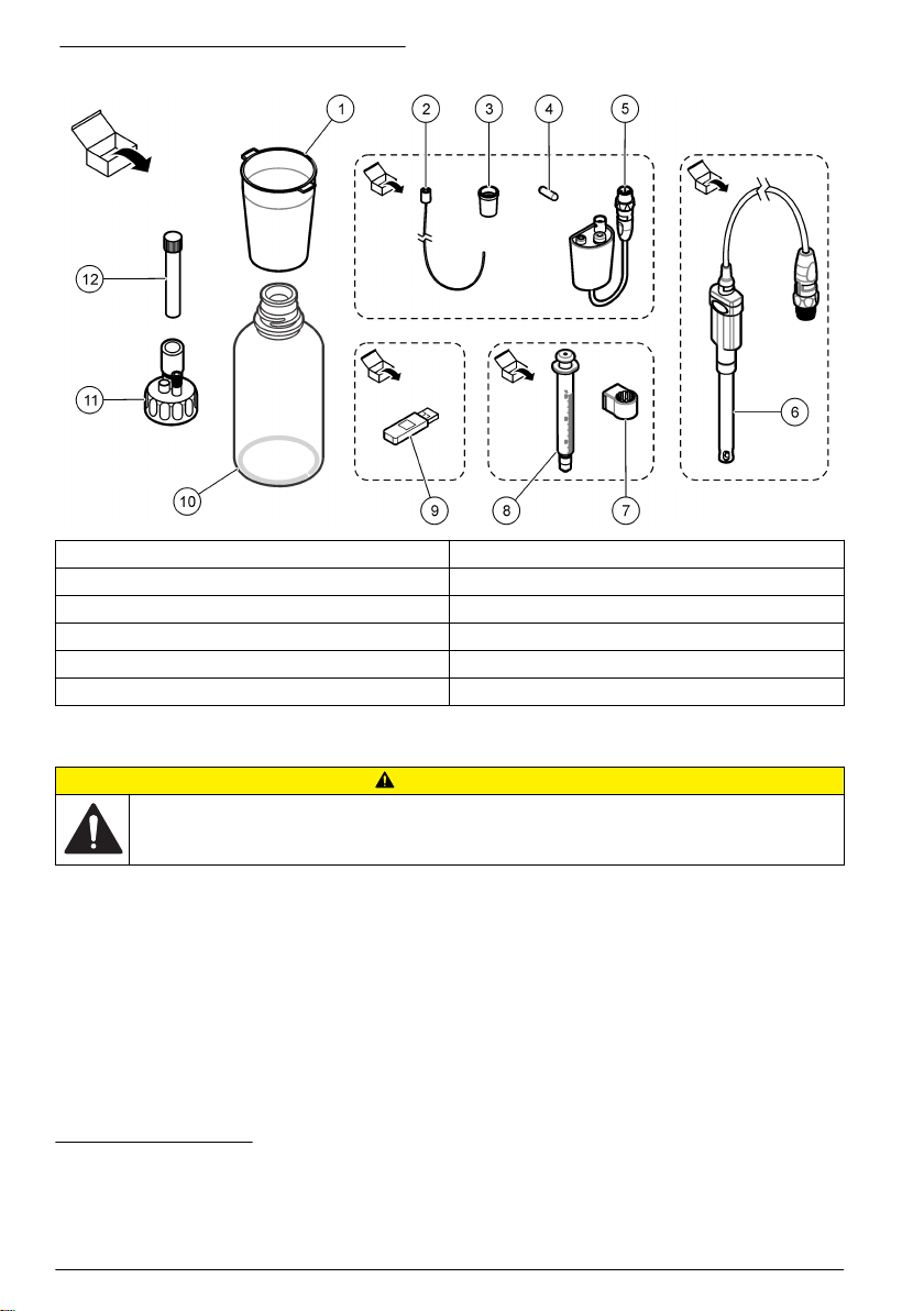
Figure 4 Contents of the application box
1 Beakers (10 x 50 mL and 10 x 150 mL) 7 Syringe holding ring5
2 Tube with anti-diffusion tip28 Syringe (refer to Table 1 on page 6 for quantity)
3 Conical adapters (2x) 9 USB applications key
4 Magnetic stir bars (10x) 10 Glass bottles6
5 Legacy sensor adapter311 Bottle caps (2 x GL45 and 1 x GL25)
6 Sensor412 Empty desiccant cartridges (3x)
Installation
CAUTION
Multiple hazards. Only qualified personnel must conduct the tasks described in this section of the
document.
The instrument is available in different configurations (refer to Table 1 on page 6). This manual
supplies instructions for the installation of an instrument with one syringe and one pump. Adjust the
installation procedure as applicable to accommodate the number of syringes and pumps in the
instrument.
Installation guidelines
• This instrument is for indoor use only.
• The power supply connector on the rear panel must be easily accessible so the power can be
disconnected quickly in case of emergency.
• Keep the instrument away from temperature extremes, including heaters, direct sunlight and other
heat sources.
51 for each syringe
2If necessary for the application
6Not in all application kits
3Not in all application kits
4Type and quantity depends on application
8 English

• Put the instrument on a stable and level surface in a well ventilated place.
• Make sure that there is at least 15 cm (6 in.) of space on all sides of the instrument to prevent
electrical parts from overheating.
• Do not operate or keep the instrument in dusty, damp or wet locations.
• Always keep the surface of the instrument and all accessories dry and clean.
Connect to AC power
D A N G E R
Electrocution hazard. If this equipment is used outdoors or in potentially wet locations, a Ground Fault
Circuit Interrupt (GFCI/GFI) device must be used for connecting the equipment to its main power
source.
CAUTION
Electrical shock and fire hazards. Make sure that the supplied cord and non‐locking plug meet the
applicable country code requirements.
WARNING
Fire hazard. Use only the power supply that is specified for this instrument.
1. Connect the power cord to the power supply.
2. Connect the power supply to the instrument. Refer to Figure 2 on page 6.
3. Connect the power cord to an electrical outlet.
Install the syringe
Before syringe installation, set the instrument power to on. Push the power button on the front of the
instrument. Make sure that the startup sequence shows on the display. The syringe holder lowers to
its operating position.
Note: Ignore any warning messages related to missing applications that show on the display.
The sensor holder has two positions: one over the magnetic stirrer and the second at 180° to the
right. Move the sensor holder away from the instrument to the second position.
Refer to the illustrated steps that follow.
To install a second syringe, do steps 5 through 7 again.
English 9

Other manuals for TitraLab AT1102
1
This manual suits for next models
3
Table of contents
Languages:
Other Hach Desktop manuals


