Haehne DMA2 Guide

HAEHNE Elektronische Messgeräte GmbH · Heinrich-Hertz-Str. 29 · D-40699 Erkrath Germany · Telefon 0211/9 25 91-0 · Fax 0211/9 25 91-20
HAEHNE
Technical modications reserved08.08 DE1DM2EA.indd
Content ......................................................................................Page
Operating Mode ............................................................................................ 2
Adjustment Modes Zero adjust calibration......................................................... 2
Amplication parameter dened by a value (gain) ............... 2
Amplication adjustment with calibration weights ................ 2
Connection / Wiring ............................................................................................ 3
Operation Preparation.......................................................................... 4
Adjustment mode ................................................................ 4
Pre-Adjustments / Operationg Modes Display intensity .................................................................. 4
Filter type of the current output ........................................... 4
Output signal range............................................................. 5
Display value....................................................................... 5
Adjustement Of The Parameters Automatic zero point adjustment ......................................... 6
Manual zero point adjustment ............................................. 6
Entering amplification as gain value.................................... 6
Amplification adjustment with calibration weights................ 7
Peak value display .............................................................. 8
Fault display during operation ............................................................................................ 8
Adjustment Instructions
Digital Strain Gauge Amplier DMA2
Operating Mode
The DMA2 is a strain gauge amplier processes sensor signals in the analog mode. The parameter values,
however, are digitally adjusted. LEDs indicate the operating status. The digital display shows the parameter
value respectively the output signal.
Adjustment Modes
Zero adjust calibration
- either
automatically by key operation (details: see page 6)
- or
manual: moving the zero point by the amount of the web weight on
the measuring/idler roll
The second possibility is useful if e.g. the web tension control system is preloaded with the dened web
weight either while in operation or at standstill. Another application can be e.g. a silo which cannot be
completely emptied and has a certain amount of weight remaining.
Amplication parameter dened by a value (gain)
In this case the gain is calculated and correspondingly adjusted
Example
Sensor data: nominal rating 1,5 m V/V
bridge supply voltage: 10 V
(the output signal is therefore 15 mV = 0.015 V at nominal force
)
Amplifier output: 10 V at nominal web tension
0 V at zero web tension
If the sensor is operating below its nominal force then the amplication must be increased.
Example
The maximum sensor load is only 75% of nominal force
.
The output signal is therefore only:
this leads to
:
Amplication adjustment with calibration weights
In this operating modes the web tension measurement equipment is loaded with calibration weights
and the amplication is adjusted accordingly. This is the more realistic but more cumbersome method.
page 2
HAEHNE Elektronische Messgeräte GmbH · Heinrich-Hertz-Str. 29 · D-40699 Erkrath Germany · Telefon 0211/9 25 91-0 · Fax 0211/9 25 91-20
HAEHNE
15 mV • 75 % = 11,25 mV
100 %
Gain = 10V = 888,88 ≈ 888,9
0,01125 V
Gain = 10V = 666,66 ≈ 666,7
0,015 V
The selected sequence of the adjustment steps is based on experience in practice situations.
Other sequences of adjustment steps are certainly possible.
08.08 DE1DM2EA.indd

page 3
HAEHNE Elektronische Messgeräte GmbH · Heinrich-Hertz-Str. 29 · D-40699 Erkrath Germany · Telefon 0211/9 25 91-0 · Fax 0211/9 25 91-20
HAEHNE
Sensor B does not exist
in case of single-sided
measurement
different connection
in case of explosion
proof applications
Connection / Wiring
Please refer to the "Practice Guide of Web Tension Measurement and Control" for wiring instructions
and the selection of the most suitable mounting location of the amplier.
Very important: Connect the shield of the sensor cable single sided on the amplier side to protection
earth (PE) with low resistance. Connect GND separately from the shield with PE.
Additional recommendation: Connect the 0 V of the 24 V circuitry at a dened place prefably in close
proximity of the PE. If this reference point is to be operated in the "oating point" mode, then the voltage
between 0 V and PE should not exceed 50 Vpp.
The four terminal blocks with ve
terminals each can be separatly
plugged in, simplifying trouble
shooting in case of faults.
V1
Output signal of full bridge
strain gauge
V2Direct voltage output
V3Dampened voltage output
V4
Excitation voltage to the full
bridge strain gauge in the sensors
V5Supply voltage 24 V DC
I1Current output (option C and N)
Sensor cable lead colors
green
yellow
brown
++
-
-
white
V
1: bridge output signal
V
4: bridge supply voltage
PE
GND
0V
green
white
brown
yellow
green
white
brown
yellow
eld
eld
PE terminal
PE terminal
08.08 DE1DM2EA.indd
+
+-
-
+
+-
-

Operation
Preparation
- Apply power to the amplifier with connected sensors. Wait 15 minutes to warm up.
- Ensure that the completely mounted sensors are loaded with the normal pre-load acting in the regular
operating mode without any additional extraneous loads. In the case of Web tension sensors this is the
roll weight without any web (foil, paper, ...)
Adjustment mode
First press and hold the SET key to switch from the operating mode into the adjustment mode, afterwards
press the menu key Ü briey and release the SET key.
The display indicates the 1. menu step which can now be changed.
For the second, third and any additional menu step do not press the SET key instead use the
menu key Ü to select the desired menu point, for instance, to make changes.
Storing of changes
Press the SET key until the LED goes OFF. This activates the adjustment procedure and the LED lights
up until the procedure is completed. The amplier switches now automatically into the operating mode.
Leaving the adjustment mode without storage
When exceeding the waiting time of 20 seconds the amplier switches without changes automatically into
the operating mode. An alternative is pressing the menu key beyond the 8. menu step.
Display intensity
(7. Menu step)
select the menu step "display intensity"
in the adjustment mode.
- select the display intensity of the LEDs
- all four LEDs blink during the adjustment
- store adjustment
Pre-Adjustments / Operating Modes
page 4
Filter type of the current output
(1. Menu step)
select the menu point "lter type"
in the adjustment mode
- select the operating mode
- LED blinks during the adjustment
- store adjustment
- if "FIL" was selected then the LED
remains ON in the operating mode
increasing
decreasing
HAEHNE Elektronische Messgeräte GmbH · Heinrich-Hertz-Str. 29 · D-40699 Erkrath Germany · Telefon 0211/9 25 91-0 · Fax 0211/9 25 91-20
HAEHNE
08.08 DE1DM2EA.indd

HAEHNE Elektronische Messgeräte GmbH · Heinrich-Hertz-Str. 29 · D-40699 Erkrath Germany · Telefon 0211/9 25 91-0 · Fax 0211/9 25 91-20
HAEHNE
page 5
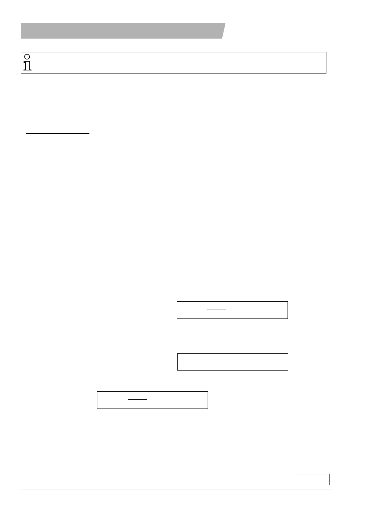
Display value
(5. Menu step)
select the menu point "display value" in the adjustment mode.
- selection alternatives:
value of the numerical display in % (factory adjustment: 100 without a decimal point)
or
as actual value in the corresponding dimensional unit (decimal point display)
- store adjustment
100 % corresponds to
10 V output voltage
increasing
The various decimal ranges are
stepped through sequentially.
The step velocity increases with the
key holding time
This adjustment deletes stored peak values!
Output signal range
(8. Menu step)
select the menu point "output signal range"
in the adjustment mode
-select operating mode
- store adjustment
Operating Mode Signal
value
Voltage
output
Current output
Option C Option N
bipolar
(factory
adjustment)
-100 % -10 V 4 mA 0 mA
0 % 0 V 4 mA 0 mA
+ 100 % +10 V 20 mA 20 mA
unipolar
-100 % 0 V 4 mA 0 mA
0 % +5 V 12 mA 10 mA
+100 % +10 V 20 mA 20 mA
The operating modes "bipolar" or
"unipolar" must be selected before zero
point and amplication adjustment!
08.08 DE1DM2EA.indd
Automatic zero point adjustment
(2. Menu step)
select the menu point "zero point adjustment"
in the adjustment mode.
- store adjustment
ALTERNATIVELY:
Adjustment of the parameters
HAEHNE Elektronische Messgeräte GmbH · Heinrich-Hertz-Str. 29 · D-40699 Erkrath Germany · Telefon 0211/9 25 91-0 · Fax 0211/9 25 91-20
HAEHNE
Manual zero point adjustment
(2. Menu step)
select the menu point "zero point adjustment"
in the adjustment mode.
- select adjustment range
- move zero point, for instance by entering the
weight of the web as a value
- store selection
increasing
decreasing
adjustment range:
-10.0 …100.%
Entering amplification as gain value
(4. Menu step)
- calculate amplification
(siehe section "Adjustment Modes" on page 2)
- if no sensor is connected then
terminals 18 + 19 or 13 + 14 have to be
connected with each other.
Select the menu point "Gain" in the adjustment mode
- select the desired amplication
- store the adjustment
increasing
decreasing
adjustment range:
400 …2800
page 6
See also: Adjustment Modes on page2
The input signal must not change during the
following adjustment procedures
The step velocity
increases with the
key holding time
The step velocity
increases with the
key holding time
The zero point must be adjusted anew In case of
manual zero point adjustment or in case of the
unipolar operating mode
ALTERNATIVELY: see next page
08.08 DE1DM2EA.indd
HAEHNE Elektronische Messgeräte GmbH · Heinrich-Hertz-Str. 29 · D-40699 Erkrath Germany · Telefon 0211/9 25 91-0 · Fax 0211/9 25 91-20
HAEHNE
page 7
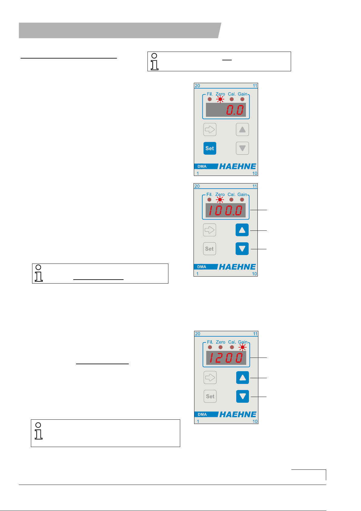
Amplication adjustment with calibration weights
(3. Menu step)
- adjust zero point (2. menu step)
- apply calibration weights to measuring a roll
- select the menu point "Cal" in the adjustment mode
- enter the percentage value of the calibration weight*
- store adjustment
increase
decrease
adjustment range:
10.0 …110.0 %
Fault conditions (Display)
"Gain": The calculated amplication is out of range and is displayed in menu step 4.
(calculated amplication as gain value)
"null": The calibration weight is too small.
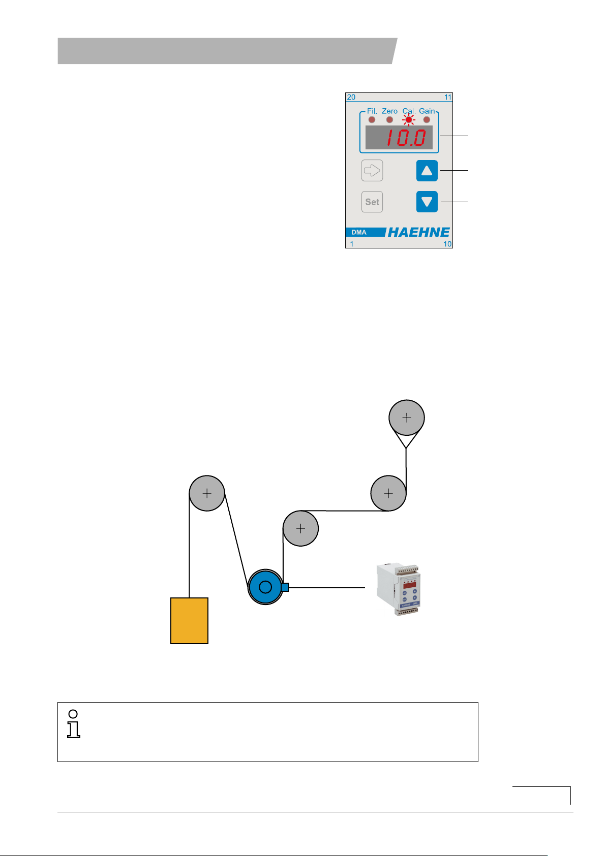
*Model the web geometry with a cable or rope and apply calibration weight. The weight should approxi-
mate the actual web tension in the operating mode. The DMA2 offers the facility to increase the weight with
a percentage calculation. As an example: 70% of the required 100 kg are applied to the measuring roll.
In the adjustment mode "Cal" 70.0 are entered representing the percentage value.
Caution: If during zero point adjustment a value unequal to 0 has been entered then value adjustments are
possible only in steps of + 10%.
The step velocity
increases with
the key holding
time
measuring roll
calibration weight
amplier
rope or
cable
08.08 DE1DM2EA.indd
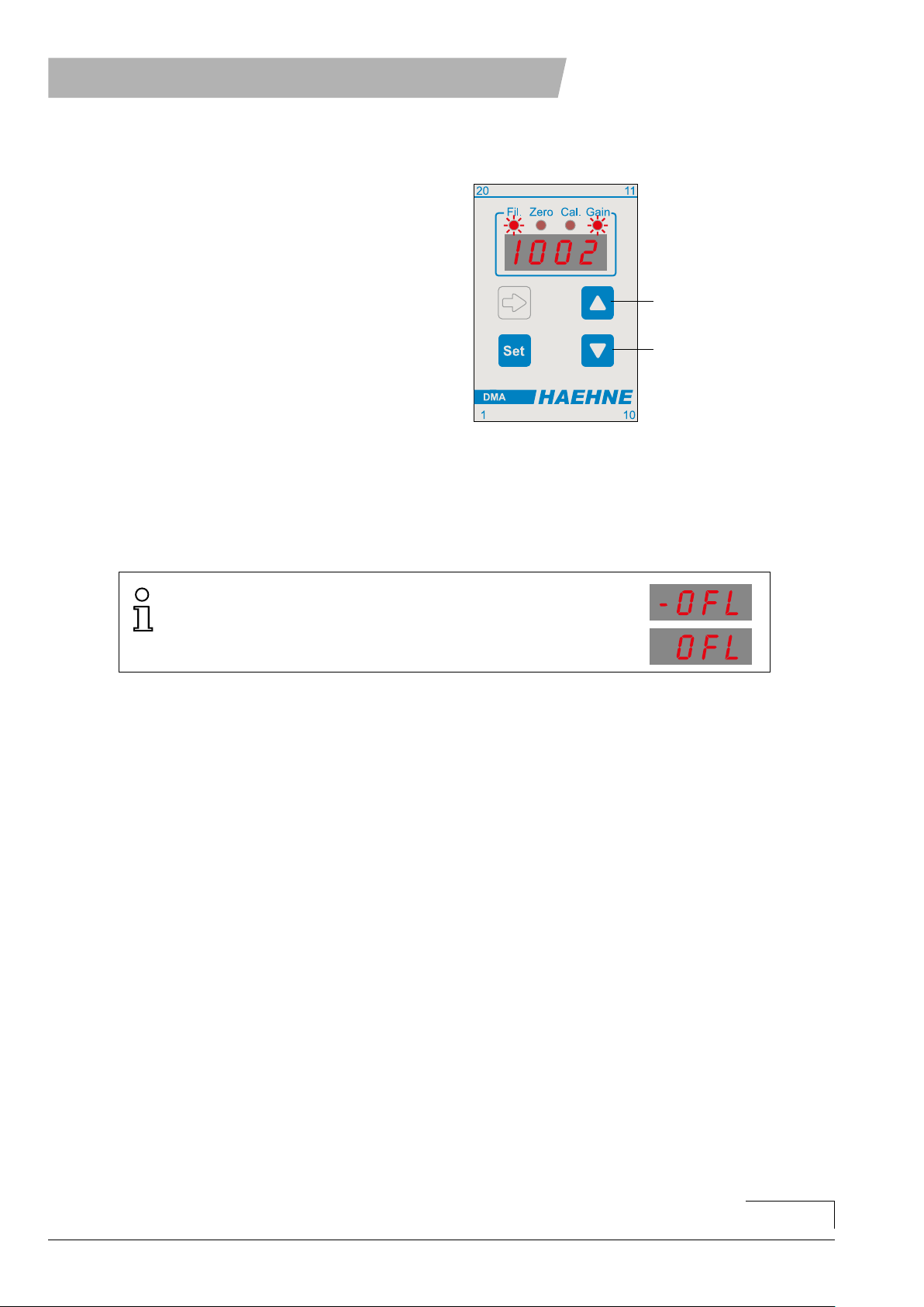
Peak value display
(6. Menu step)
- read stored peak values
A change of the output signal range or the
displayed value will return the display to null.
- erase the value with the "SET" key
max. value
min. value
Fault display during operation
Exceeding the maximum output signal voltage of approximately
(-) 13.3 V e.g. resulting from a broken sensor cable.
HAEHNE Elektronische Messgeräte GmbH · Heinrich-Hertz-Str. 29 · D-40699 Erkrath Germany · Telefon 0211/9 25 91-0 · Fax 0211/9 25 91-20
HAEHNE
page 8
08.08 DE1DM2EA.indd
Table of contents
Other Haehne Amplifier manuals


