KE-USBMX20 Operating Tips
Please check the following items before contacting us.
• When connecting the KE-USBMX20 to a PC use a standard
USB A- micro B type Cable. Maximum length 15 ft.
• Check the KE-USBMX20 configuration. Check the matrix
configuration for the number of Columns, Rows, etc. Review
the matrix table for the desired responses.
• If the keypad attached to the header has a connecting cable
(such as with a membrane switch) be sure it is no more than
10 feet in length.
• The KE-USBMX20 scans a matrix size in any combination
of the pins from 1 x 8, to 4 x 5. This arrangement allows
for scanning of most keypads up to a 20 key matrix. When
using less than the full 9 pins on the KE-USBMX20, insert the
included keying plug to help with the header alignment.
• When using a macro sequence, a break or release of a key
must be made for any make or press of the key that was done
earlier in the macro.
• The KE-USBMX20 sends keystrokes. To get a specific
character, a macro may need to be created to emulate the
same sequence normally used to manually type the character.
For example, “$” is a shifted “4” key on the USA keyboard. The
macro for “$” would make (press) the Shift, then make the
“4” key, then break (release) both keys.
*Note: For any questions that are not answered in this
manual, please send us an email or call customer service. We
have customer service available from 8:00 am to 5:00 pm (EST)
Monday through Friday.
Toll Free 888-690-9080, or (540) 465-4677
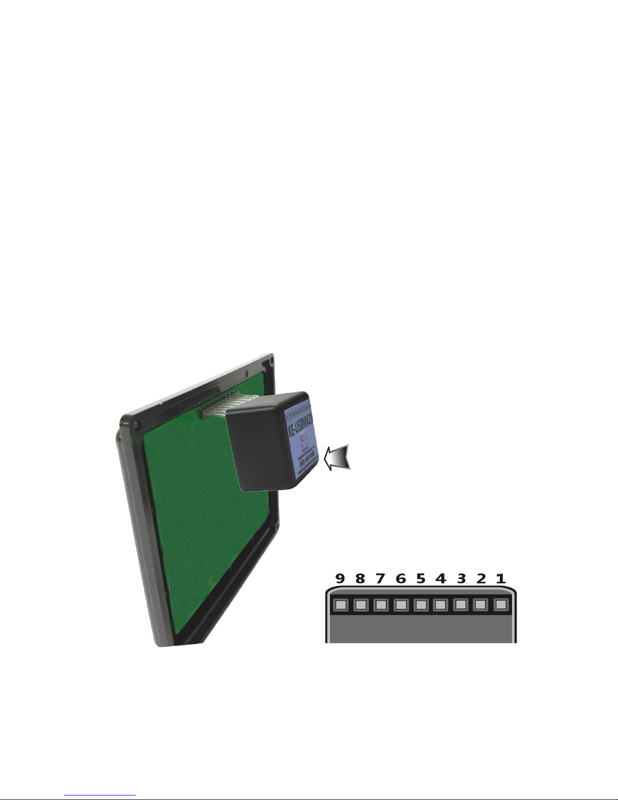
Interfacing to the KE-USBMX20 Header
The header on the KE-USBMX20 consists of 9 configurable pins.
The pins are designated as “1” through “9”.
Use the supplied KE-USBMX20.EXE program to configure the
header pins as either Rows or Columns. Keystrokes are initiated
by shorting a Row pin to a Column pin through a contact closure.
The pins that are defined as Columns will sink current while
scanning the matrix. The Rows are used to read the status of
the inputs when a Column is active.
Keypads with male headers can be directly plugged onto the KE-
USBMX20 connector. KE-USBMX20 pins can be configured to
be either Rows or Columns to allow for this direct attachment.
*Note: Keypads with male pins may be connected directly. For
membrane keypads with female headers, adapters may be used
to directly connect from the pigtail to the KE-USBMX20 header.
(See Accessories on page 20)
322
View of the 9 pin female
header pin designations as
seen from the bottom of the
KE-USBMX20
The KE-USBMX20 header
connects directly to the
keypad header. Secure with
the adhesive pad included
or with your own fastening
system.