manuals.online logo
Brands
  1. Home
  2. •
  3. Brands
  4. •
  5. HaiLin Controls
  6. •
  7. Thermostat
  8. •
  9. HaiLin Controls HA309 User manual

HaiLin Controls HA309 User manual

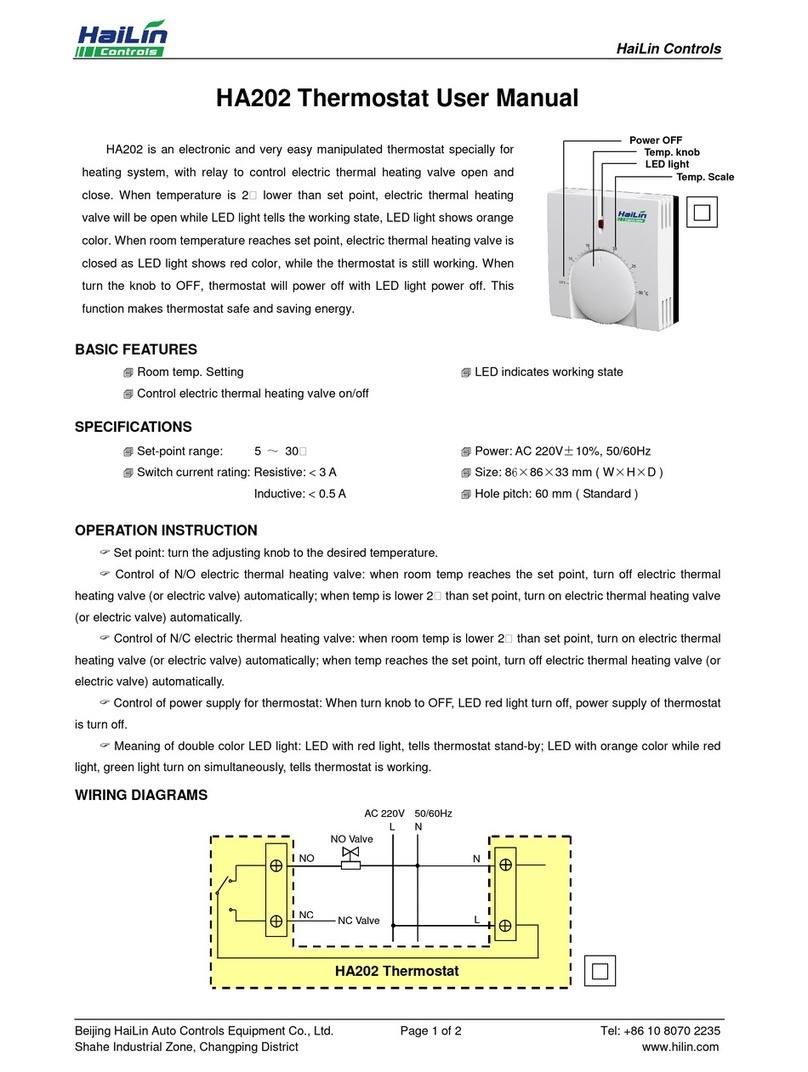
HA309 Thermostat User Manual
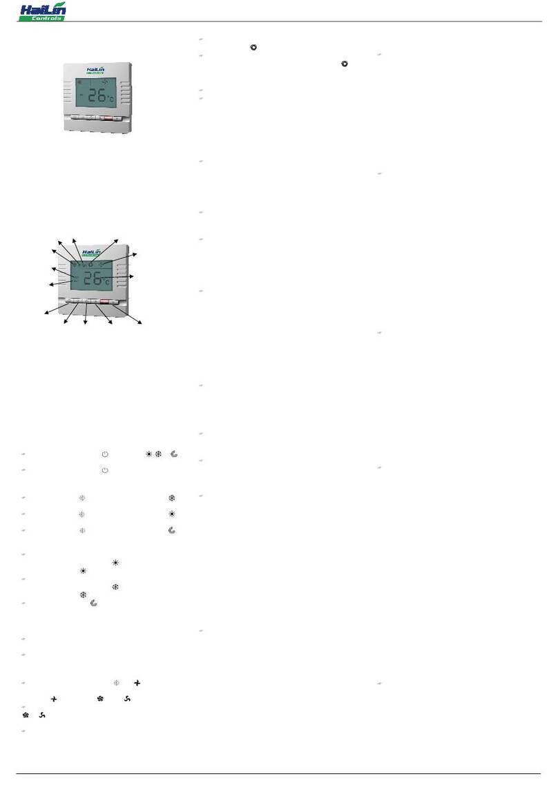
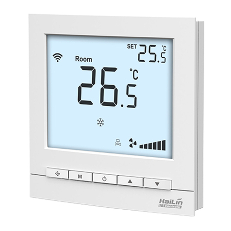
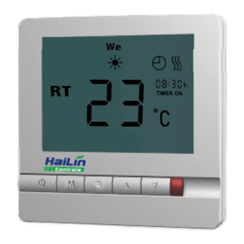
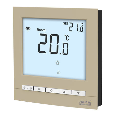
HA309 thermostat is luxurious in appearance with a large LCD display screen special for
electrical heating. It is available for room temperature control in residential, industrial and
business premises, controlling the on/off of the electrical heating equipment, to achieve comfort
and energy saving purposes.
HA309,
the thermostat shows indoor temperature, floor temperature, setting temperature,
thermostat output state, and time through the use of micro-computer control technology with big
LCD display screen.
HA309’s buttons include: Power, Mode, Time, Temperature Regulator(Up/Down)Backlit,
Program,Reset, with sensor alarm light (Alarm).
BASIC FEATURES STATUS DISPLAY
Room temperature setting and measurement
Floor temperature setting and measurement
Manual/Timer/4 periods programmable
4 periods programmable mode:5+2/6+1/7days
Celsius /Fahrenheit, 24/12 hours
Room highest/lowest temperature range setting
Floor highest/lowest temperature range setting
Relay Pick-up Times inquiry
Restoring factory settings
Sensor fault alarm
Difference adjustable function
Sensor for room only/floor only/both room and floor
Low-temperature protection
Auto Recovery
Green backlight
Room temperature display
Room setting temperature display
Floor temperature display
Floor setting temperature display
Degrees Celsius shows ℃
Fahrenheit shows ℉
Thermostat output states
Thermostat output delay display
Preheat output displayed in advance
Time display
Week display
4 periods display
SPECIFICATIONS
Sensing element: NTC
Set-point range: (could set upper/lower limit)
Inside sensor:5-35℃[41-95℉]
Outside sensor:5-45℃[41-113℉]
Only outside sensor:0-90℃[32-194℉]
Operating temperature: 0-45℃[32-113℉]
Operating humidity: 5-95%RH ( non-condensing )
Button: Silicone Rubber Keypad
Power supply: AC85-250V,50/60Hz
Power consumption: <3W
Wirings: Wiring 0.0016x0.0062sq. in.( 1×4 mm2 wires)
Switch current rating: 16 A(Resistive)
Housing: PC+ABS Flame Retardant
Dimensions:2.95x4.82x1.04”
(75×122.5×26.5mm) (W×H×D)
Hole pitch: 3.29” (83.5 mm)(standard)
Protection class:IP30
OPERATION
On/Off: Press “POWER” to turn on, press “POWER” again to turn off, and off the electric heating equipment at the same time.
Setting temperature: When power is on, press “Down” to reduce set-point, press “Up” to raise set-point. (0.5℃ [1℉] changed each press.)
Electric heating equipment’s control: When the room temperature is 1℃(when the offset is 2℉) lower than the setting temperature, the thermostat will put through the power of the
electric heating equipment, and the LCD will display “ ”; When the room temperature is 1℃(when the offset is 2℉) higher than the setting temperature, the thermostat will close the power of
the electric heating equipment, and “ ” will disappear.
If open the ”output delay” function, (refer to No.15 and No.16 of the parameter list): “ ” flashing means delaying, and the thermostat will output. When the delay time shows, the LCD
shows “ ”, the thermostat output, and put through the power of the electric heating equipment.
MANUAL MODE、TIMER ON/OFF FUNCTION MODE AND 4 PERIODS MODE CHOICES
Timer on: Press “Mode” for 3 seconds, LCD shows “XX”, press “Up” or “Down” to adjust the parameter.
“01” stands for manual mode, that means after set the temperature, and no change, LCD shows “ ”.
“02” stands for timer on/off mode, LCD shows “ ”.
“03” stands for 4 periods mode, LCD shows corresponding time symbol.
4 PERIODS’ CORRESPONDING SYMBOLS:
Period 1 Period 2 Period 3 Period 4
Wake Leave Return Sleep
TIMER AND TIMER ON/OFF FUNCTION SETTING
Time adjust: press “Time”, till to display “hh:mm” and “hh” flashes,press “Up” or “Down” to adjust hour; press “Time”, “mm” flashes, press “Up” or “Down” to adjust minute; press “Time”,
then week flashes, press “Up” or “Down” to adjust week.
Timer on: Press “Time”, till to display “TIMER ON” and “hh” flashes,press “Up” or “Down” to adjust time on hour, press “Time”, “mm” flashes, press “Up” or “Down” to adjust the time
on minute; Press “Time”, till “TIMER OFF” and “hh” flashes. Use the above method, setting the time on/off hour and minute, the time on/off will be valid until to be canceled.
Canceling timer on: Method 1: Setting the time on/off hour and minute as “00”; Method 2: As per the tip of the “manual mode, timer on/off function mode and 4 periods mode choices”,
switch the mode to manual “01” or 4 periods “03”.
4 EVENTS PROGRAMMING SETTING
Dividing a week into seven separate days or 5+2/6+1(Monday….Friday + Sat Sun/ Mon….Sat + Sun), each day has four periods with different setting temperature to meet with
customer’s individual demand.
Temperature unit default is Fahrenheit, if need to change into Degrees Celsius, please refer to “parameter setting datasheet”.
Taking Working days (Mon-Fri), Resting days (Sat-Sun) 4 periods setting as an example, reference as below:
Working day setting : period 1 setting : press “Prog” ,and LCD shows “ ” and “Mon Tue Wed Thu Fri”, “hh” flashes in “hh:mm”, and then press “Up” or “Down” to set hours; press
“Prog”, “mm” flashes in “hh:mm”, and then press “Up” or “Down” to set minutes; press “Prog”, temperature flashes, and then press “Up” or “Down” to set the temperature, and the other time
period is set by the same way.
Resting day setting: Press “Prog” till to show “ ” and “Sat Sun” and then set as the above method.
Please separate each time period when set the above time period, so as to avoid the system work fault.
This thermostat has installed following initial values:
5+2
Working days/Resting
days
Period 1 Period 2 Period 3 Period 4
Starting T / temp.℃Starting T / temp.℃Starting T / temp.℃Starting T / temp.℃
Working days(Mon-Fri)
7:00 20℃[68℉]
8:30 16℃[61℉] 17:00 22℃[72℉]
21:30 18℃[64℉]
Resting days(Sat-Sun)
7:30 21℃[70℉]
9:00 20℃[68℉] 17:30 22℃[72℉]
22:00 18℃[64℉]
Cancelling Working days /Resting days 4 periods function, please as per the tip of the “manual mode, timer on/off function mode and 4 periods mode choices” , switch the mode to
manual ”01” or timer on/off “02”.
Taking Working days, Resting day 4 periods setting as an example, this thermostat has installed following initial values:
6+1
Working days/Resting
days
Period 1 Period 2 Period 3 Period 4
Starting T / temp.℃Starting T / temp.℃Starting T / temp.℃Starting T / temp.℃
Working days(Mon- Sat)
7:00 20℃[68℉] 8:30 16℃[61℉] 17:00 22℃[72℉]
21:30 18℃[64℉]
Resting day(Sun)7:30 21℃[70℉] 9:00 20℃[68℉] 17:30 22℃[72℉]
22:00 18℃[64℉]
Take each day’s 4 periods of a week (7days) as an example, reference as below:
7 days 4 periods programmable: Separate each day into 4 periods, each period includes the start time and the programmable temperature.
Before follow below steps to program the 7days, please layout the starting time and temperature.
Press “Prog”, LCD shows “ ” and “Mon”, as per the initial value datasheet and follow steps to set the 4 periods program of Mon. “hh” flashes in “hh:mm”, press “Up”, “Down” to set the
hour of the program. Press “Prog”, “mm” flashes in “hh:mm”, press “Up” or “Down” to set the minute of the program. Press “Prog”, program temperature flashes, press “Up”, “Down” to set the
program temperature.
1. Press “Prog”, “hh” flashes in “hh:mm”, press “Up”, “Down” to set the hour of the second period program.
2. Press “Prog”, “mm” flashes in “hh:mm”, press “Up”, “Down” to set the minute of the second period program.
3. Press “Prog”, program temperature flashes, press “Up” or “Down” to set the adjustable temperature.
4. Repeat 1-3 steps to set the 3-4 periods of Mon.
5. Press “Prog”, show “ ” and “Tue”. Repeat 1-4 steps to set the 1-4 periods of Tue.
6. Repeat 1-5 steps to set Wed, Thu, Fri, Sat, Sun.
This thermostat has installed following initial values:
Week Period 1 Period 2 Period 3 Period 4
Starting T / temp.℃Starting T / temp.℃Starting T / temp.℃Starting T / temp.℃
Mon 7:00 20℃[68℉] 8:30 16℃[61℉] 17:00 22℃[72℉] 21:30 18 ℃[64℉]
Tue 7:00 20℃[68℉] 8:30 16℃[61℉] 17:00 22℃[72℉] 21:30 18℃[64℉]
Wed 7:00 20℃[68℉] 8:30 16℃[61℉] 17:00 22℃[72℉] 21:30 18℃[64℉]
Thu 7:00 20℃[68℉] 8:30 16℃[61℉] 17:00 22℃[72℉] 21:30 18℃[64℉]
Fri 7:00 20℃[68℉] 8:30 16℃[61℉] 17:00 22℃[72℉] 21:30 18℃[64℉]
Sat 7:30 21℃[70℉] 9:00 20℃[68℉] 17:30 22℃[72℉] 22:00 18℃[64℉]
Sun 7:30 21℃[70℉] 9:00 20℃[68℉] 17:30 22℃[72℉] 22:00 18℃[64℉]
PARAMETER SETTING LIST
Power off, press “mode” and “time” button at the same time and hold for 6 seconds, enter the parameter setting interface. Now press “clock” button to page down and “mode” button to
page up selecting parameter, and press “up” and “down” button to adjust the parameter value.
NO. Parameter Setting Description Default Value Range
01 CC
Thermostat working time counter 0-1999 Days
02 Pr
4 periods mode choices:
52=5+2 4 periods;61=6+1 4 periods;74=7 4 periods;
no=have no 4 periods, it is manual or time on/off mode. no 5+2 4 periods
6+1 4 periods
7days 4 periods
03 rH
Setting the highest room temperature range 35℃95℉10-45℃50-113℉
04 rL
Setting the lowest room temperature range 5℃41℉3-9℃37-48℉
05 FH
Setting the highest floor temperature range 45℃113℉
20-60℃68-140℉
06 FL
Setting the lowest floor temperature range 5℃41℉5-10℃41-50℉
07 CF
Celsius /Fahrenheit, 24/12 hours :12℃,24℃,12℉,24℉24℃
08 Fr
Low temperature protecting function on/off: 0=off;1=on 0 0-1
09 dB
Difference setting 2℃/℉1-9℃/℉
10 5E
Sensor mode: 0=only inside; 1=only outside;2=both inside and outside.
0 0-2
11 rC
Room temperature adjustment 0℃/℉-9-9℃/℉
12 FC
Floor temperature adjustment 0℃/℉-9-9℃/℉
13 BC
Compensation factor adjustment 47 30-99
14 dd
Auto recovery: 0=auto recovery;1=no auto recovery;2=power on 0 0-2
15 rE
When power re-supplied, relay time adjustable.
Default =0, relay time is 10 seconds 0 min 0-15min
16 DE
Temperature-variation caused relay off-on process time set 0 min 0-15min
17 O5
Auto-adjustable function on and off 0=off, 1=on 0 0-1
18 OP
Preheat output displayed in advance setting 3h 0-3h
19 CO
Set preheat output value 20min
10min
10-120min
5-60min
20 Oh
Set only outside sensor‘s highest temperature 90℃194℉
30-90℃85-194℉
21 OL
Set only outside sensor‘s lowest temperature 0℃32℉0-10℃32-50℉
NOTE:
(*) Only Auto-adjustable function on, parameter shows No.18, No.19.
(**) Only choose single outside sensor, parameter shows No. 20, No.21.
FLOOR TEMPERATURE EXAMINATION AND SETTING
Check the floor temperature: power on status, press “Mode” one time, LCD shows “ ”, “XX.X℃” or “XX℉” shows the floor temperature. Single sensor setting is without this function.
Set the floor temperature: power off status: press “Mode” for 7 seconds, until LCD shows “SET XX.X℃” or “SET XX℉”, then press “Up” or “Down” to set the floor protection
temperature. Default Setting is 35℃ [95℉].
LOW TEMPERATURE PROTECTION
When the low temperature protection is valid, thermostat turns off and the room temperature (or floor temperature) is lower than 5℃[41℉], the thermostat will auto start heating and
show “ ”, turn on the electric heating equipment, when the room temperature (or floor temperature) increases to 7℃[45℉], the thermostat will end output auto.
The on /off of the low temperature protection function, please refer to the “Parameter Setting Table”.
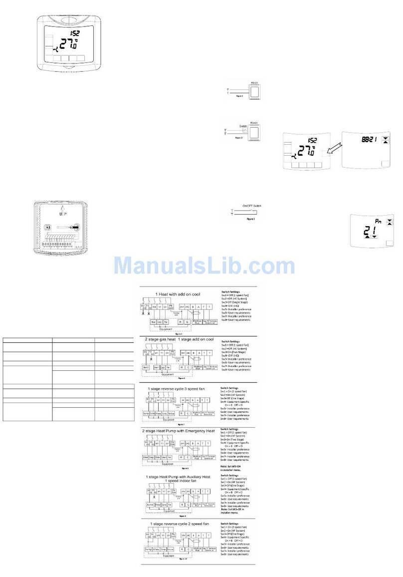
WIRING DIAGRAM
Note:
1. Wire all circuits as Class 1, Electric Light or Power Circuits, including the Sensor input.
2. The length of the outside sensor cannot be longer than 45.72 ft. (15m). The sensor needs to be housed in a suitable plastic enclosure and the sensor leads voltage have to be rated
not less than the maximum rated line voltage of the device.
3. Only one sensor style: If only inside sensor’s fault, LCD shows “E0”; If only outside sensor’s fault, LCD shows “E1”.
Both inside and outside sensor: inside sensor fault, LCD shows ”E0”, outside sensor fault, LCD shows “E2”.
If any above fault happened, alarm will flash, and the thermostat will turn off the output
.
INSTALLATION
The device should be installed in place at least 32.81 ft. (10 meters) from the electrical service panel.
Note: Connect all wires as per the wiring
diagrams and keep it away from water, mud
and other materials.
1. Fix the mounting plate
with the screws.
2. Wire according to the
wiring program.
3. Push the button to install the
product into the mounting plate.
4. Lock the screw.

Other HaiLin Controls Thermostat manuals

HaiLin Controls Lake Extra User manual

HaiLin Controls

HaiLin Controls Lake Extra User manual

HaiLin Controls A4100 User guide

HaiLin Controls

HaiLin Controls A4100 User guide

HaiLin Controls HL116 Series User manual

HaiLin Controls

HaiLin Controls HL116 Series User manual

HaiLin Controls HA202 User manual

HaiLin Controls

HaiLin Controls HA202 User manual

HaiLin Controls HL-ESNC-027 User manual

HaiLin Controls

HaiLin Controls HL-ESNC-027 User manual

HaiLin Controls HL8102 Series User manual

HaiLin Controls

HaiLin Controls HL8102 Series User manual

HaiLin Controls HL109 Series User manual

HaiLin Controls

HaiLin Controls HL109 Series User manual

HaiLin Controls HL2023DA User manual

HaiLin Controls

HaiLin Controls HL2023DA User manual

HaiLin Controls HL8102 Series User manual

HaiLin Controls

HaiLin Controls HL8102 Series User manual

HaiLin Controls HL8002-MD Series User manual

HaiLin Controls

HaiLin Controls HL8002-MD Series User manual

HaiLin Controls HA202 User manual

HaiLin Controls

HaiLin Controls HA202 User manual

HaiLin Controls HL8001 User manual

HaiLin Controls

HaiLin Controls HL8001 User manual

HaiLin Controls HA808-MD User manual

HaiLin Controls

HaiLin Controls HA808-MD User manual

HaiLin Controls HL2023 Series User manual

HaiLin Controls

HaiLin Controls HL2023 Series User manual

HaiLin Controls HL-ESNC-025 User manual

HaiLin Controls

HaiLin Controls HL-ESNC-025 User manual

HaiLin Controls Elegance SMT-700 User manual

HaiLin Controls

HaiLin Controls Elegance SMT-700 User manual

HaiLin Controls A2203 User manual

HaiLin Controls

HaiLin Controls A2203 User manual

Popular Thermostat manuals by other brands

ICP TSTAT0711 owner's manual

ICP

ICP TSTAT0711 owner's manual

Honeywell Super Tradeline T874G installation instructions

Honeywell

Honeywell Super Tradeline T874G installation instructions

Neotherm Futura Z Pro manual

Neotherm

Neotherm Futura Z Pro manual

Salus HTR24 Installer manual

Salus

Salus HTR24 Installer manual

nvent Raychem T-M-20-S/+X+Y/EX manual

nvent

nvent Raychem T-M-20-S/+X+Y/EX manual

Aube Technologies TH131AF user guide

Aube Technologies

Aube Technologies TH131AF user guide

Johnson Controls T6000 Series installation instructions

Johnson Controls

Johnson Controls T6000 Series installation instructions

Lorenzoni LOR-THERM 355 instruction manual

Lorenzoni

Lorenzoni LOR-THERM 355 instruction manual

ritetemp 6008 Operation guide

ritetemp

ritetemp 6008 Operation guide

Lennox LB57113BM Installation insrtuctions

Lennox

Lennox LB57113BM Installation insrtuctions

Vive TP-N-801 installation manual

Vive

Vive TP-N-801 installation manual

Fidure A1-730 installation guide

Fidure

Fidure A1-730 installation guide

Venstar T1900 installation instructions

Venstar

Venstar T1900 installation instructions

Honeywell Lyric T5 Wi-Fi Quick install guide

Honeywell

Honeywell Lyric T5 Wi-Fi Quick install guide

Honeywell Home T6 Pro Smart installation instructions

Honeywell Home

Honeywell Home T6 Pro Smart installation instructions

Giacomini K492DY012 manual

Giacomini

Giacomini K492DY012 manual

Heatmiser smartstat user manual

Heatmiser

Heatmiser smartstat user manual

Theben RAMSES 818 top 6 A operating instructions

Theben

Theben RAMSES 818 top 6 A operating instructions

manuals.online logo
manuals.online logoBrands
  • About & Mission
  • Contact us
  • Privacy Policy
  • Terms and Conditions

Copyright 2025 Manuals.Online. All Rights Reserved.