Hakko Electronics Matala 25L User manual

for 110V-120V

-1
WARNING
IMPORTANT SAFEGUARDS READ AND
FOLLOW ALL SAFETY INSTRUCTIONS
DANGER
To avoid possible equipment electric shock, special care should be taken when the pump
is used as aeration equipment. For each of the following situations, do not attempt to
repair yourself, return the air pump to an authorized service facility for servicing, or
discard the pump.
I) If the pump falls into the water, DO NOT REACH FOR IT: first unplug the pump, and
then retrieve it.
If the pump’s electrical components get wet, unplug the pump immediately.
II) Carefully examine the air pump after installation. It should not be plugged in if there
is water on parts that are not intended to be wet.
III) Do not operate if the cord or plug is damaged, or if the pump is malfunctioning,
dropped, or damaged in any way.
IV) To prevent the plug of electrical outlet getting wet, position the water tank and stand
to one side of a wall mounted outlet.
This should avoid water dripping onto the plug or outlet.
A drip loop shown in the (Figure 1), should be arranged for each cord connection an air
pump to an electrical outlet. The drip loop is that part of the cord below the level of the
outlet or connector if an extension cord is used. The drip loop prevents water traveling
along the cord and coming into outlet.
If the plug of outlet does get wet, DO NOT UNPLUG THE CORD: Disconnect the fuse or circuit
breaker supplying power to the pump. Then unplug and examine for the presence of water in the
outlet.
V) Do not use the pump near volatile liquids such as gasoline, thinners, etc, as this creates the
possibility of an explosion.
CAUTIONS FOR USE
A) Close supervision is necessary when an appliance is used or near children.
B) This pump is air-operated. Do not, under any circumstances, attempt operation with water or
other liquids, otherwise pump may be damaged.
C) The temperature range may result in malfunction of severely shortened service life.

-2
D) Do no block the air being discharged. Pump must have sufficient room to allow for heat
dissipation.
Under the extreme operating temperature conditions which may be caused by failure to
Observe cautions C) or D), pump will automatically switch off until cool. DO NOT REMOVE
PUMP CASING UNTIL UNIT IS DISCONNECT FROM MAIN SUPPLY.
E) Always unplug pump prior to servicing. Grasp plug to remove cord form outlet. Do not
remove by pulling on power cord.
F) Do not use the air pump for any other purpose which different from its original use. Use of
unauthorized replacement parts may jeopardize safety.
G) Do not store pump under freezing condition.
H) Ensure pump is securely mounted prior to operation.
I) Read and observe all important markings on pump.
J) Ensure that extension cords (if require) have the correct or higher rating (amperes or watts).
Ensure cord is properly positioned to avoid tripping.
INSTRUCTIONS NOTES
1. INSTALLATION
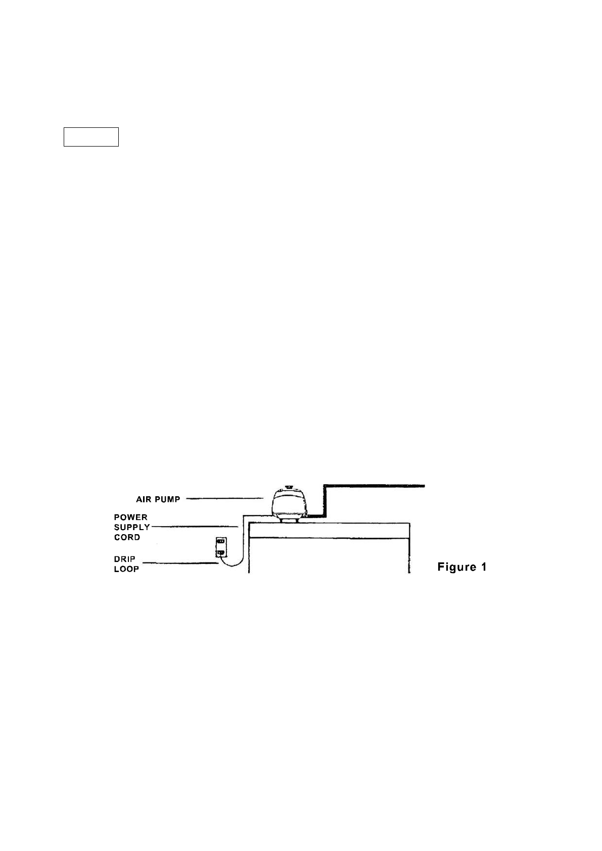
A) When using the pump to inject air into a liquid, ensure the pump is placed higher than the
surface level of the liquid, otherwise the liquid may run back into the pump when the power is
turned off.
B) Do not keep the air pump in a damp and stuffy place.
C) Please ensure the air pump is placed on a strongly built place horizontally.
2. GROUNDING
This air pump must be grounded to minimize the possibility of electric shock.
This air pump is equipped with an electric cord having an equipment grounding conductor and a
grounding type plug. The plug must be plugged into an outlet that is properly installed and
grounded in accordance with all appropriate codes and ordinances.
DANGER –Improper Installation of the grounding plug can result in a risk of electric shock. If
repair or replacement of the cord or plug is necessary, do not connect the grounding wire to
either flat blade terminal. The wire with insulation having other surface that is green with or
without yellow stripes is the grounding wire.
Check with a qualified electrician or serviceman if the grounding instructions are not completely
understood, or if in doubt as to whether the product is properly grounded. Do not modify the plug
provided; if it will not fit the outlet, have the proper outlet installed by a qualified electrician.
This air pump is for use on a nominal 110-120 volt circuit as indicated on the sticker, and has a
grounded plug which is illustrated in (Figure 2). Carefully read the specification on the nominal

-3
volt circuit as indicated on the sticker! For Canada, USA: the nominal volt circuit is 110-120 volt.
Australia is 240 volt. 220 volt for other countries.
3. OPERATION AND MAINTENANCE
When the pump is connected to a proper receptacle, the pump will operate.
The filter must be periodically cleaned or replaced. The air pump has no sliding parts and
therefore no need for lubrication. Also the exhausted the air pump is always clean. This air pump
has no user serviceable parts.
ASSEMBLY AND OPERATIONAL INSTRUCTIONS
1. Inspect unit for any damage due to shipment.
2. Ensure that no parts are missing.
3. The AIR PUMP is designed to be positioned horizontally. Ensure that the location is dry and
free of excessive dust or debris. Dust protection around the entire unit may be constructed of
furnace filters. Please ensure the air circulation is maintained all the time.
4. The air pump should be placed above water level to ensure no siphoning can occur if power
failed. A proper installed check valve will prevent backflow and allow placement of the pump
below water surface level.
5. For store requirement. The air pump should be attached to a permanent pie assembly with
minimum diameter of pump outlet (18mm) Rigid plastic pipe is preferable over flexible hosing
for valve attachment. Air valve should be tapped into this line to supply individual aerations
with standard aeration airline. Teflon tape on valve threads will reduce air leakage from the
pipe.
6. Outside diameter of the output stem is 18mm, hose can be directly attached for straight line
installation, or provided elbow can be used if a corner is required.
7. See figures outlining typical set-ups for proper installation of rigid pipe assembly. Do not
block air pump’s output. Excessive backpressure will prematurely damage diaphragm.
8. If the air pump produces more air than required, bleed excess into atmosphere with a valve
to reduce damaging backpressure.
NOTE:
FULL LOOP PROVIDES EVEN AIR PRESSURE TO ALL AREAS OF INSTALLATION.

-4

-5

-6

-7

-8

-9

-10
MAINTENANCE
Cleaning the filter: FILTER MUST BE CLEANED EVERY 6 MONTHS
I) Undo the cover bolt securing the filter cover to the
pump housing, and remove the filter pad. (Figure 3)
II) Gently dust the filter pad then wash in mild, soapy
water and dry.
III) Replace the filter pad and filter cover. Secure with
the cover bolt.
Connecting the Piping: IMPROPER CONNECTION
WILL CAUSE LEAKAGE OF AIR
I) Connect the pump’s exhaust port and PVC (Plastic) pipe with an
L-shaped rubber hose.
II) Secure place of connection with a
hose tightening clip (Figure 4).
Removing the Pump Housing
1. Changing the casing block
I) Invert the pump and remove corner screws. (Figure 5a)
II) Insert screw driver between
exhaust outlet and upper
housing and try open gently. (Figure 5b)
III) Remove the assembly
screws on the left and right of the
diaphragm Casing. Remove the
diaphragm Casing from diaphragm
frame and disconnect L-tube. Replace
with new casing block.
IV) Put back in place, ensure all
screws are tight. (Figure 5c)
Replacing the Diaphragm Mounting Block
I) Undo the six sides U-Nut in the center of the frame.
II) Remove and replace frame. (Figure 6)
III) Reassemble, ensure tightness of screws.
Inserting a new Magnet
Insert the rod into the slot on the side of the
diaphragm frame and then slide into the motor
unit. The rod should be positioned with the “S”
at the top. (Figure 7)

-11
List of repair parts for 25L-120LH
Magnet
1 pcs per set
25L/25LP
HK-M25
40L/40LP
HK-M40
60L/80L
HK-M60/80
80LH
HK-M80H
100L
HK-M100/150
120L/120LH
HK-M120/120H/200
Chamber Block
2 pcs per set
Includes:
Casing Block
Diaphragm Mounting Block
25L/25LP
HK-D25
40L/40LP
HK-D40
60L/80L/80LH
HK-D60/80
100L/120L/120LH
HK-D100/120
Filter Pad
1 pcs per set
25LP/40LP
HK-F25LP/40LP
40L/60L/80L/80LH
HK-F40/60/80
100L/120L/120LH
HK-F100/120
Specifications
‧The above specifications are subject to change without prior notice.
Note:
The air pumps are application of inhaling and exhaling. The pump uses of exhaling function, then inhaling
hole function to air filter. Air filter necessary to be cleaned, periodicity (Pump put in outside every 3
months, inside every 6 months).
25L 25LP 40LP 40L 60L 80L/80LH 100L 120L/120LH
2.9 / 82 3.5 / 100 4.2 / 119 4.8 / 137
2.56 / 0.18 2.85 / 0.20
2.30 / 65 2.97 / 84 3.60 / 102 4.38 / 124
61 82 110 130
32 36 35 39 38 38 40 42
Psi 6.7 7.68 6.5 7
Kg-f/cm20.46 0.54 0.45 0.49
9 / 4 7.8 / 3.5 10.8 / 4.9 13 / 5.7
Noise level(dB)
5.0
0.34
6.28
0.44
Model
Specification
Max flow
(cfm) / (lpm)
1.1 / 32
2.5 / 70
60
AC 110/115/120
20 / 9.2
15 / 6.7
Rated voltage(V)
Power supply frequency(Hz)
Rated pressure (psi) / (bar)
Exhaust quantity(cfm) / (lpm)
1.42 / 0.10
0.92 / 26
1.85 / 0.13
1.59 / 45
2.13 / 0.15
24
38
Weight (lbs) / (kg)
Closed
pressure
Power(W)

-12
List of repair parts 150L-250L
Magnet
1 pcs per set
150L
HK-M100/150 x2set
200L
HK-M120/120H/200 x2set
250L
HK-M250 x2set
Chamber
Block
2 pcs per set
Includes:
Casing Block
Diaphragm Mounting Block
150L
200L
250L
HK-D100/120 x2set
Filter Pad
1 pcs per set
150L
200L
250L
HK-F150/200/250
Specifications
‧The above specifications are subject to change without prior notice.
Note:
The air pumps are application of inhaling and exhaling. The pump uses of exhaling function, then
inhaling hole function to air filter. Air filter necessary to be cleaned, periodicity (Pump put in outside
every 3 months, inside every 6 months).
150L 200L 250L
7.8 / 220 11.8 / 335 13.2 / 375
2.85 / 0.20 2.85 / 0.20 2.85 / 0.20
5.5 / 155 7.24 / 205 9.00 / 255
145 160 227
52 54 56
Psi 5.7 5.1 5.7
Kg-f/cm20.4 0.35 0.4
33.5 / 15.2
Noise level(dB)
Model
Specification
Max flow
(cfm) / (lpm)
60
AC 110/115/120
Rated voltage(V)
Power supply frequency(Hz)
Rated pressure (psi) / (bar)
Exhaust quantity(cfm) / (lpm)
Weight (lbs) / (kg)
Closed
pressure
Power(W)

-13
MATALA WATER TECHNOLOGY CO., LTD.
GUARANTEE PROVISIONS
1) This Air pump/compressor has a limited guarantee for 3 year from the date of
purchase provided that:
[a] It is operated in accordance with the instruction manual.
[b] Any repairs to the Air pump, which must be accompanied by this certificate are
undertaken or authorized by the dealer or distributor from whom it was purchased.
[c] Warranty is void if electrical cord is cut or if pump has been flooded.
[d] Warranty does not include diaphragms, magnet or air filter.
*Diaphragm-----item no.5,6 for 25L, item no.7,8 for 25LP,
item no.12,13 for 40LP, item no.11,12 for 40L~120LH,
item no. 9,10 for 150~250L
*Magnet----------item no.4 for 25L, item no.11 for 25LP/40LP,
item no.10 for 40L~120LH,
item no.15 for 150~250L
*Filter--------------item no.3 for 25LP/40LP, 150L~250L
item no.4 for 40L~120LH
2) Though the guarantee period may not have expired, payment for repairs must be
made in the following cases:
[a] When the fault is due to improper usage or repairs have been attempted by
persons other than an authorized dealer.
[b] When the fault is due to fire, natural disaster or incorrect voltage.
[c] If the guarantee has been lost, incorrectly completed or details fraudulently
changed.
3) Original purchase receipt and serial# must be retained and provided to Authorized
Dealer and Authorized Distributor for this warranty to be valid.

-14
100L, 120L, 120LH TROUBLE SHOOTING
A. If you plug power cable but Air Pump do not turn-on:
1. Please open the Pump housing (Please see operation manual page 5 Process 1~5) and check the
parts 8 (Security Stopper).
If the Security Stopper the Triangle symbol like (picture 1) is wrong. That is because the shipment or
people who movement the air pump in wrong way. Please use the screw driver or coin turn the
Triangle symbol like (picture 2).
2. Put the Air pump cover back then plug in the power cable turn on again.
B. If your pump running after several days or several weeks then stop:
Please open the air pump housing (Please see operation manual page 5 Process 1~5) and cheek the
parts 13 (Magnet)
If you see the Magnet position already shift (please see the picture 3) not in the middle of
Electromagnet (Please see operation manual page 5 Part 7) then please use screw driver to move the
Magnet back to the normal position (Please see the picture 4).

-15
MATALA LINEAR AIR PUMP DIAPHRAGM REBUILD INSTRUCTIONS
MATALA 40L, 60L, 80L, 80LH shown
Your new diaphragm kit includes two diaphragms. Each diaphragm consists of two
halves. Also included is a bag with new nuts and washers.
Tools you will need: Flat head screw driver, Phillips head screw driver, Adjustable
wrench.
1) Remove top filter cover and filter pad.
2) Turn pump over and unscrew the 4 screws which connect the body to the base.
3) Use a flat head screw driver to pry outer metal body away from the base.
4) Remove body.
5) Inspect motor for burned wire, torn rubber hoses, fine metal dust. Clean gently with
damp paper towel.
6) Repair only one diaphragm at a time. Remove the black J-tube from diaphragm outlet.
Once removed, just push the top of tube to the side out of the way.

-16
7) Use a Phillips screw driver and remove the 4 screws which connect the diaphragm to
the motor plate. You might have to use a flat head screw driver to separate the two
halves of the diaphragm.
8) Use an adjustable wrench to remove the nut on the diaphragm. This will separate the
magnet.
9) Tap or push the center screw in order to separate the diaphragm from the magnet.
You might need to use a flat head screw driver to separate the diaphragm from the
motor plate.
*At this point you will have a better look at the magnet. The magnet rarely needs to be
replaced. If there is a lot of fine metal dust in the motor area then the magnet may
need to be replaced. Inspect the top and bottom part of the magnet. If it looks very
worn or melted proceed to the optional section on “How to Replace the Magnet”.
10) Inspect one new diaphragm. There are two halved for each diaphragm. Notice that
the half with the round soft rubber looks different on each side. One side has a
rectangular impression. This impression must line up with the magnet screw. There is
also an oval peg on the hard black plastic part which must align properly with the
motor plate.

-17
11) Align the new half diaphragm properly with the magnet screw and the motor plate.
Push the diaphragm completely until it touches the magnet screw. You might need to
push the soft rubber from behind with your finger. Use the wrench to screw on the
new washer and nut. Be sure the new nut is very tight. (You may also use a drop of
removable” Lock-Tight” glue to secure the nut to the magnet.)
12) Again, properly align the hard plastic with the motor plate. Be sure it is set flush with
the motor plate and the oval plug is aligned with hole in motor plate. Now, align the
second outer half diaphragm with the first half screw holes. Squeeze both halves
together with your fingers really hard. The two halves will not completely connect until
you screw them together.
13) Screw the 4 screws in just a little at a time while gradually increasing the torque.
Progress around the screws gradually tightening evenly until both halves are fully
connected and tight with the motor plate.
14) Replace the black J-Tube over the diaphragm outlet. Use existing clip to secure tube
to outlet.
Repeat these instructions for the second diaphragm starting at #6.

-18
15) After both diaphragms have been replaced.
16) Replace the outer metal housing onto the base and tighten the 4 screw. Wash the
square air filter with tap water and shake dry. Reinstall into the top of metal housing
and replace the filter cover. Congratulations, you’ve done it!

-19
DISTRIBUTED BY
MATALA WATER TECHNOLOGY CO., LTD.
www.matala.com.tw
171213
This manual suits for next models
9
Table of contents
Other Hakko Electronics Water Pump manuals
Popular Water Pump manuals by other brands

Stanley
Stanley SXUP400PCE instructions

Grundfos
Grundfos LC 241 Installation and operating instructions

Pentair
Pentair MYERS MCSP3I owner's manual

Ingersoll-Rand
Ingersoll-Rand MP PUMPS CHEMFLO 3 Operator's manual

DAISHIN
DAISHIN CORAL SCR252M2 Instructions for use

Wilo
Wilo Atmos TERA SCH 150-555 Installation and operating instructions

ITC
ITC MULTIFERTIC manual

SAMES KREMLIN
SAMES KREMLIN REXSON SH207 user manual

Graco
Graco G-Mini 25R800 instructions

Agilent Technologies
Agilent Technologies Turbo-V 1K-G Series user manual

Agilent Technologies
Agilent Technologies TPS-compact user manual

Xylem
Xylem Lowara MP Installation, operation and maintenance instructions