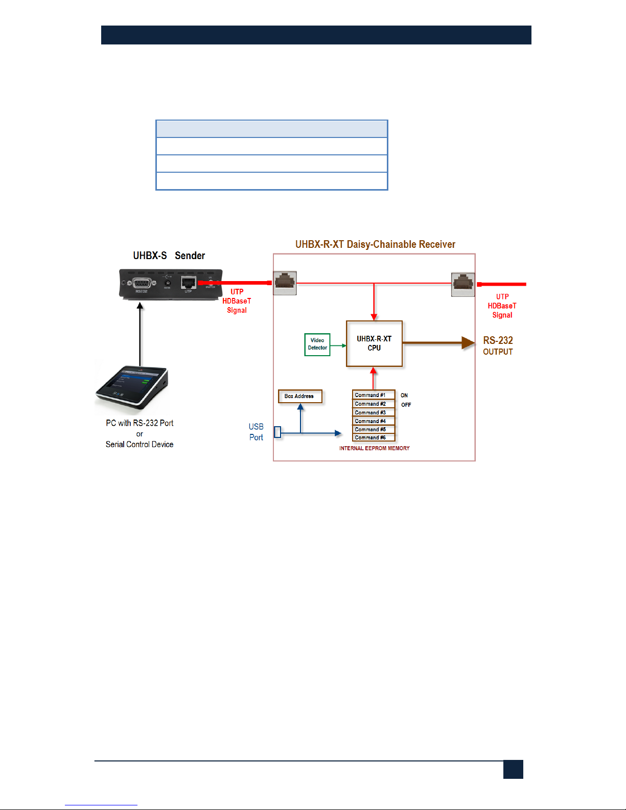
1.1 HDBaseT Daisy Chain
The video source needs to be connected to a compatible transmitter. Please
refer to section 3.1 below for a table listing of compatible senders.
Up to 8 UHBX-R-XT Receivers can be connected in a daisy chain. The last
unit in the daisy chain can be a lower cost receiver with no daisy-chain output
such as: UH-1BT-R, UH1-BTX-R, or UHBX-R. However, the serial port
function will not be compatible. Therefore, if you are using the addressable
serial port feature (see section 4.5), then the last unit in the daisy chain will
also have to be a UHBX-R-XT.
2.0 Features
•Extends uncompressed HDMI video, RS232, and IR, up to 500 feet
on a single CAT6
•Supports multiple units in daisy-chain to allow extending video and
data to very long distances
•At Full-HD (1080p), up to 8 receives can be daisy chained
•Individually addressable RS-232 ports on each receiver for
controlling connected displays
•Can be directed to send out RS-232 commands on the fly, or to send
any of the commands programmed in its internal memory
•Can detect video and use RS-232 to turn displays on and off
automatically (from commands uploaded to its internal memory)
•Multiple units in the daisy chain can be individually addressed
•IR extension (from source to all receivers)
•Supports HDCP, 3D and Deep color
•Sturdy metal enclosures with L brackets for mounting
•Complies fully with HDBaseT standard
•Compact, Rugged, Reliable, and Economical
•Made in USA
2.1 Package Contents
Qty (1) UHBX-R-XT
Qty (1) 5V DC Universal Power Adapter
Qty (1) 1m/3ft USB to Mini-USB Cable
Qty (1) User’s Manual