Function Blocks PSx-3__-PN
10
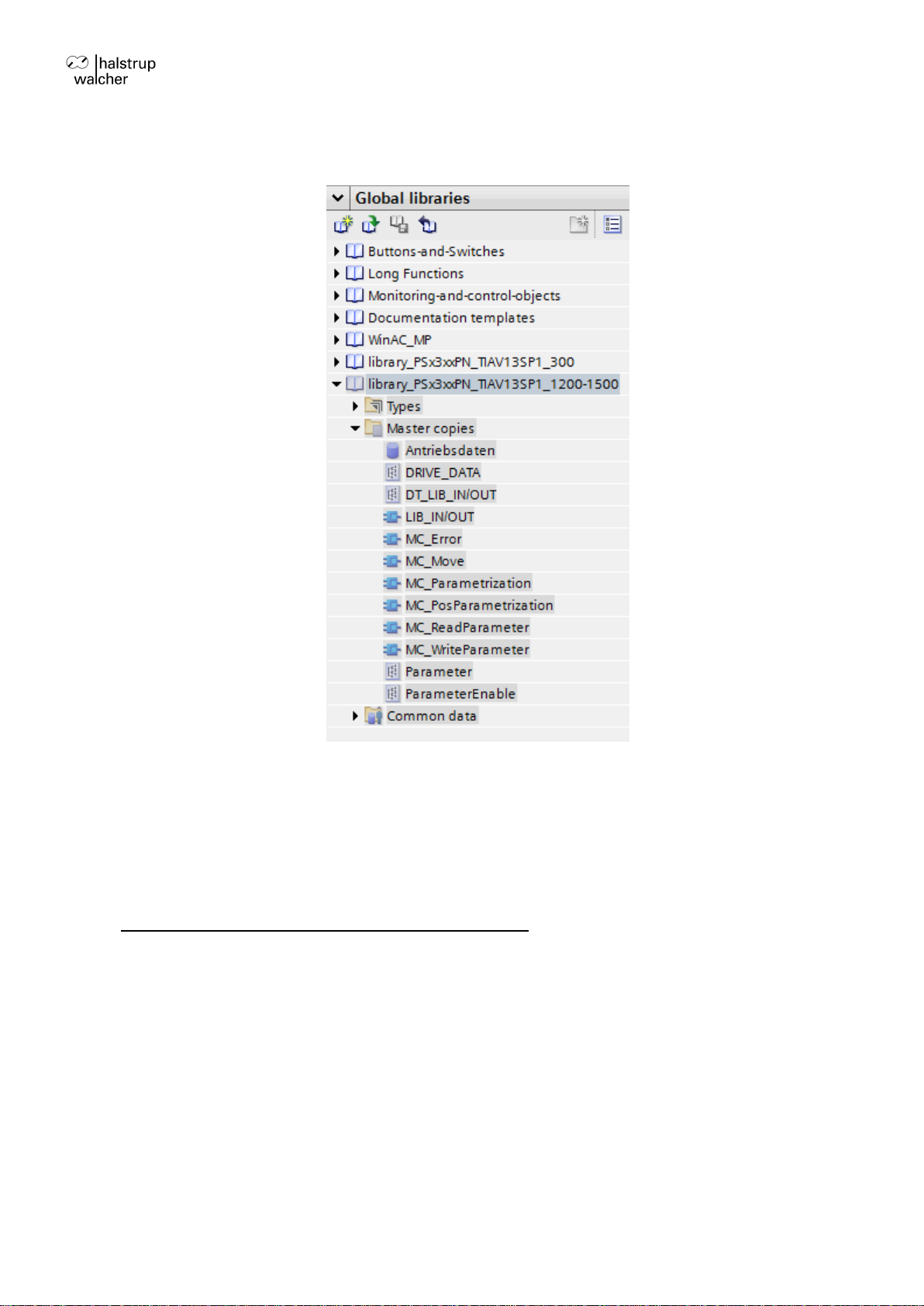
When using one of the library versions for Step 7 TIA V13 + V14:
Copy into “Program blocks”of the desired CPU:
Data type DRIVE_DATA
Data type DT_LIB_IN/OUT
Function block LIB_IN/OUT
These elements serve for the communication to the drive. The functions and function blocks of
this group must NOT be called in the program.
Besides the desired function blocks “MC_...” have to be copied into the user project, e.g. all or
a choice of the following blocks:
MC_Move
MC_Error
MC_ReadParameter
MC_WriteParameter
MC_Parametrization
MC_ PosParametrization
In the versions for the TIA Portal additionally the data component “Antriebsdaten”may be
taken over as a template for connecting the inputs and outputs of the function blocks. In ist
standard implementation, the data types “Parameter”and “ParameterEnable”also have to be
taken over (see chapter 3).
5.3 Generating instance data blocks
Per axis and per desired function block an instance data block has be generated.
5.4 Generating global data
Per axis one global variable of the type DRIVE_DATA has to be generated (size: 94 byte in
Classic Step 7, 144 byte in TIA Portal). Additionally those variables have to be generated
which are connected to the inputs and outputs of the particular blocks.
If applicable, it’s reasonable to generate an additional data block of the type “global” for this
data (e.g. DB1000), in case of the TIA Portal also the template “Antriebsdaten” may be used
(see chapter 3).
It’s not necessary to connect all inputs and outputs. If parts of a block are not used, the
associated inputs may stay unconnected, then the respective initial value for this input is valid.
Outputs not used also may stay open.
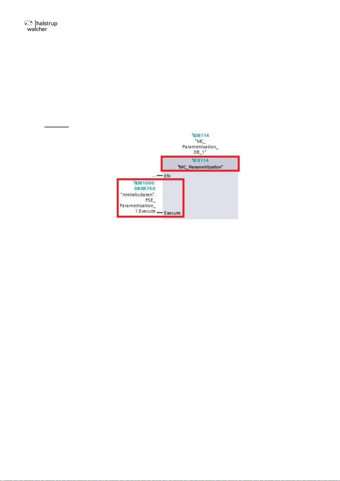
5.5 Commonalities of all function blocks
The function blocks are inserted in a part of the program that is called cyclically (e.g. in the
OB1) and immediately be linked with their respective instance data blocks.