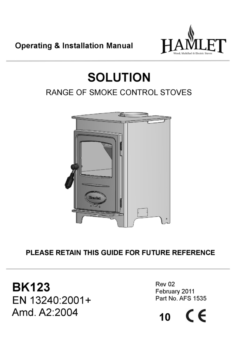
Hamlet Solution Inset 5 User manual

BK096
EN 13240:2004+
Amd. A2:2004
PLEASE RETAIN THIS GUIDE FOR FUTURE REFERENCE
SOLUTION INSET
Multi-Fuel Grate Installation Instructions
Rev. 01
September 2009
Part No. AFS1460
Solution Inset Shown With Multi-Fuel Grate Fitted

Page No.
Part Identification table 3
Fitting the Comb & Extension Bar 4
Assembling the Grate 5
Fitting the Grate 6
Solid Fuel Burning 7
Final Factor Check List 8
Hamlet Solution Inset
CONTENTS
Page 2
Please note, if you require any further information or assistance,
then please call the technical support department on -
0844 847 5107

Hamlet Solution Inset Page 3
PART IDENTIFICATION TABLE
Part Description Visual Aid ( Not to Scale ) Part Number
Multi Fuel Kit
(includes Fixings) MFKITINSET5
* Grate bar support
( Back Landing) 1 x AFS1327
* Grate bar comb &
Extension 1 x AFS1413
* Grate Bar 5 x AFS0001
* Plus / Minus bracket 1 x AFS1412
** Inner Wood Cover Plates
(Includes Fixings 1 x AFS1404
** Outer Wood Cover Plates
(Includes Fixings 1 x AFS1333
** Wood Burning Tray 1 x AFS1401
* components included in Multi-Fuel Kit ( MFKITINSET5 )
** components standard with wood burning version of stove as despatched
Not included in factory fitted multi-fuel version

FITTING THE GRATE
The Grate
The grate in the Hamlet Solution Inset stove,
comprises of a series of reciprocating cast iron
grate bars, seated on a pivoted ‘comb’. All bars in
the grate are identical, but every other bar is
turned through 180 degrees, with the ends of the
bars marked ‘H’ sitting on the high sections of the
comb, and the ends marked ‘L’ sitting on the low
sections.
Assembling The Grate
If you have purchased the riddling grate bar set as
an upgrade to a wood only burning stove you will
need to remove the following items before
commencing with the assembly and fitting of the
grate. ( see page 3 for identification images)
1. Remove the fuel retainer bars.
2. Remove the wood tray (AFS 1401)
3. Remove the Inner and Outer
Wood cover plate set (AFS 1404)
See Fig 1 & 2
To assemble the grate,
First fit the rear grate bar support (AFS 1327 ) into
the left and right Side Landing slots as shown in
Fig 3.
Next fit the comb and comb extension bar as
follows:-
Feed the comb extension bar through the hole in
the body of the stove from the outer face with the
slotted end inside the stove. Insert the comb into
the hole in the left stove side landing. Align the slot
so as to allow the end section of the comb and pin
to drop into the receiving slot and hole in the
extension bar. Check for free movement by
‘riddling’ the comb extension bar.
See Fig 4 a-d. (page 5)
Fit the grate bars to the low sections of the comb
first, inserting ends marked ‘H’ into the rear
channel with the groove on the underside of the
bar located on the up stand tab, and then lowering
end marked ‘L’ onto the low section of the comb,
see Fig. 5. (page 6)
The upper bar is fitted in a similar manner, but with
the end marked ‘L’ inserted in the rear channel,
and the end marked ‘H’ seated on the high section
of the comb. See Fig. 6. for the assembled grate
layout.
Fig 1
Fig 2
Rear grate bar support fitted.
Fig 3
Inner wood cover
plate
Outer wood cover
plate
Hamlet Solution Inset
Page 4
ASSEMBLY PROCEDURE

Hamlet Solution Inset Page 5
Fig 4a
Insert Comb extension
though the stove body
Section views are for clarity
Fig 4b
Slot and hole aligned
vertically
ASSEMBLY PROCEDURE
Fig 4c Fig 4d
Left and right end
comb insertion
Left hand end in
left landing
Right hand end
inserted into comb
extension

NOTE:
When the grate assembly & installation is complete
re-fit the 2 no. fuel retainer bars, that were removed
earlier.
Grate Bar Replacement
After extended use it may be necessary to replace
some of the grate bars. Periodic inspection of the
bars is recommended and the removal of any nails or
wire that may be present after burning wood. All the
grate bars in each appliance are identical and can
easily be lifted out after the removal of the fuel
retainers. Remove damaged grate bars and replace
with castings of the same type, fitting as per the
instructions on page 4. When re-ordering
replacement grate bar, See page 3 of these
instructions for the correct spare part code.
Fig 5
Fig 6
Fig 7
Wood / Coal bracket, replaces the Outer
Wood Cover Plate
Page 6 Hamlet Solution Inset
ASSEMBLY PROCEDURE
Wood Coal bracket
The wood coal bracket replaces the outer wood
cover plate, and is attached using the same
screws once removed. See fig 7.
The multi-purpose tool to supplied with the stove
can be use to ‘riddle’ the grate when burning
solid fuel, and to set the grate position for fuel
types.
The upper ‘+’ position is best suited for coal and
the lower ‘-’ position is generally for the burning
of wood.

Page 7
Hamlet Solution Inset
BURNING SOLID FUEL
SOLID FUEL BURNING
Set the grate t the ‘+’ position
Ensure the ash pan is in position
Set the air wash to one quarter open
Set the primary air inlet to fully open
See PRIMARY AIR Section opposite
Light as normal with kindling or fire lighter
If a gas poker is used be sure to remove it as
soon as the fire is alight
Close the fire door
When the fire is well alight regulate the burning
rate by controlling the primary air inlet control
The air wash can be opened sufficiently to keep
the door glass clean
MIXED FUELS
The grate can be set to either Wood or Coal
position depending on the main percentage of
the fuel to be burnt
As per coal but allow addition secondary air
The primary air inlet can be closed and burning
regulated by means of the air wash above the
door (s)
ANTHRACITE
Anthricite is more difficult to keep in for long
periods, consequently more care in setting the
controls and some familiarisation is necessary
when burning Anthracite.
Use small size fuels (Stovesse or Small Nuts)
Proceed as for manufactured smokless fuel. Leave
the air inlet control open about a quarter or less.
EXTENDED BURNING
The appliance will burn for extended periods
provided:-
Sufficient fuel is placed in the firebox
The controls are correctly set
Excess draught is not present in the chimney
The door is closed
If the fire goes out with un burnt fuel in the
firebox increase the air opening slightly, and
vice versa.
In The Morning
Open the air controls fully until embers begin to
glow brightly, then place pieces of fuel on the fire
until it is well established. Complete re-fuelling can
now be undertaken
IMPORTANT
Stop using the appliance if you smell
fumes or see smoke escaping.
If fume emission does persist, the following
immediate actions should be taken :
Open doors and windows to ventilate room.
Let the fire die or extinguish and safely dispose
of fuel from the appliance.
Check for flue or chimney blockage, and clean if
required.
Seek expert advice from your HETAS
registered installer. Do not attempt to re-light
the fire until the cause of the fume emission
has been identified and corrected.
PRIMARY AIR
Air enters the appliance through the control on the
bottom of the fire door. The Hamlet Solution has a
single control knob which slide left to right. Sliding
the knob to the Right (+), will increase the amount
of air intake to the stove. To decrease, push the
slider to the Left (-)
Fully Open Position
Fully Closed Position
Quality / Finish
Grate Bars
Rear Grate Bar Support
Comb
Comb Extension
Plus / Minus Bracket
I’ve checked it
and its O.K !
Assembled By…………………….
Checked by………………………..
Final Factory Check list
Stove Model …………….………………
Serial No. ……………………………….
Arada Ltd
The Fire Works
Weycroft Avenue
Axminster
Devon
EX13 5HU
United Kingdom
Tel: +44(0)1297 35700 Fax: +44(0)1297 35900 www.arada.uk.com
Table of contents
Other Hamlet Stove manuals

Hamlet
Hamlet DEFRA User manual

Hamlet
Hamlet Solution 5 Widescreen User manual

Hamlet
Hamlet BK055 Manual

Hamlet
Hamlet Solution Manual

Hamlet
Hamlet Hamlet Solution S4 User manual

Hamlet
Hamlet Hero Deluxe Manual

Hamlet
Hamlet Camborne Manual

Hamlet
Hamlet BK540 User manual

Hamlet
Hamlet Solution Manual

Hamlet
Hamlet Hereford Manual
Popular Stove manuals by other brands

THERMOROSSI
THERMOROSSI URBAN Installation, use and maintenance guide

MCZ
MCZ GIO 2016 installation guide

Desa
Desa SBVBP OWNER'S OPERATION AND INSTALLATION MANUAL

Royal
Royal Alida Air 120 manual

Napoleon
Napoleon EPA 1100 Installation and operation instructions

Outwell
Outwell RUKUTU STOVE instruction manual