Hammer HB 450 User manual

HYDRAULIC BREAKER
HAMMER HB 450


TABLE OF CONTENTS
1. FOREWORD ........................................................................................................................................................................................................4
1.1 Operating manual.....................................................................................................................................................................................4
1.2 Important safety information...............................................................................................................................................................4
1.3 Warranty.......................................................................................................................................................................................................5
1.4 Spare part orders.......................................................................................................................................................................................5
2. MACHINE NUMBERS ......................................................................................................................................................................................6
2.1 model and serial number.......................................................................................................................................................................6
3. PRODUCT INTRODUCTION..........................................................................................................................................................................7
3.1 Overview ......................................................................................................................................................................................................7
3.2 Removal from package...........................................................................................................................................................................7
3.3 Lifting instructions...................................................................................................................................................................................7
3.3.1. Provided lifting points .......................................................................................................................................................................8
3.4 Safety instructions for lifting..............................................................................................................................................................10
3.5 Main parts..................................................................................................................................................................................................11
4. SAFETY...............................................................................................................................................................................................................12
4.1 General safety ..........................................................................................................................................................................................12
4.2 Safety instructions..................................................................................................................................................................................12
5. OPERATION......................................................................................................................................................................................................18
5.1. Operating instructions .........................................................................................................................................................................18
5.2 Daily operation....................................................................................................................................................................................... 22
5.3Mounting and dismounting the hammer.......................................................................................................................................27
5.4 Installation................................................................................................................................................................................................ 28
5.5 Movement................................................................................................................................................................................................ 28
5.6 Special conditions of use ................................................................................................................................................................... 28
5.7 Storage....................................................................................................................................................................................................... 29
5.8 Turning hammer left- or right-handed .......................................................................................................................................... 30
6. HAMMER TOOL GREASING .......................................................................................................................................................................32
6.1 Recommended greases ........................................................................................................................................................................32
6.2 Manual greasing......................................................................................................................................................................................32
6.3 Automatic greasing................................................................................................................................................................................33
7. CARRIER HYDRAULIC OIL.......................................................................................................................................................................... 34
7.1 Requirements for hydraulic oil .......................................................................................................................................................... 34
7.2 Oil cooler ................................................................................................................................................................................................... 36
7.3 Oil lter....................................................................................................................................................................................................... 36
8. ROUTINE MAINTENANCE.......................................................................................................................................................................... 38
8.1 Overview ................................................................................................................................................................................................... 38
8.2 Inspection and maintenance by the operator............................................................................................................................ 38
8.3 Inspection and maintenance by the dealer ................................................................................................................................. 38
8.4 Maintenance intervals in special applications .............................................................................................................................39
8.5 Other maintenance procedures....................................................................................................................................................... 40
9. REMOVAL OF TOOL...................................................................................................................................................................................... 40
10. LOWER TOOL BUSHING............................................................................................................................................................................42
11. TROUBLESHOOTING ..................................................................................................................................................................................43
11.1 the hammer does not start................................................................................................................................................................43
11. 2 The hammer operates irregularly butthe blow has full power........................................................................................... 44
11. 3 The hammer operates irregularly andblow has no power ................................................................................................... 44
11.4 Impact rate slows down .................................................................................................................................................................... 44
11. 5 The hammer does not stop or has run-on.................................................................................................................................. 45
11. 6 Oil overheats.......................................................................................................................................................................................... 45
11.7 Recurrent tool failure.......................................................................................................................................................................... 46
11. 8 Automatic greasing device problems .......................................................................................................................................... 46
11.9 Further assistance .................................................................................................................................................................................47
12. HAMMER SPECIFICATIONS..................................................................................................................................................................... 48
12.1 technical specications...................................................................................................................................................................... 49
13. MAIN DIMENSIONS ................................................................................................................................................................................... 40
14. TOOL SPECIFICATIONS............................................................................................................................................................................. 50

4
FOREWORD
1. FOREWORD
1.1 OPERATING MANUAL
This data transfer document is arranged to provide necessary product information for documentation
team when designing their manuals. Document contains information of the equipment and its safe
operation. It also contains maintenance information, technical specications and service instructions.
1.2 IMPORTANT SAFETY INFORMATION
Basic safety precautions are outlined in the «Safety» section of this manualand in the description of
operations where hazards exist. Warning labelshave also been put on the machine to provide instructions
and to identifyspecic hazards which if not observed could cause bodily injury or death toyou or other
persons. These warnings in the guide and on the machine labels are identied by the warning symbol.
To use the attachment correctly, you must also be a competent operator ofthe carrier machine. Do not
use or install it if you can not use the carrier machine properly. The attachment is a powerful tool. If used
without propercare, it can cause damage.
Do not rush when you are learning to use the product. Take your time andmost importantly, take it
safely. Do not guess. If there is anything you do notunderstand, ask your local dealer. He will be pleased to
advise you.Improper operation, lubrication or maintenance of this machine can be dangerous and could
result in injury.
Do not operate this machine until you read and understand the instructionsin this manual.
Do not perform any lubrication and maintenance on this machine until youread and understand the
instructions in this manual.

5
FOREWORD
1.3 WARRANTY
A complete warranty claim for a hydraulic breaker attachment includes atleast the following information.
- Model and serial number
- Carrier model
- Installation: Oil ow, operating pressure and return line pressure ifknown
- Working hours and service history
- Application
Providing this information makes it easy to handle the warranty claim properly and swiftly.
INSTALLATION INSPECTION
An installation inspection must be carried out after the product has been in-stalled on the carrier. In the
installation inspection certain specications (operating pressure, oil ow, etc.) are checked so that they are
within givenlimits. See “Hammer specications”.
1.4 SPARE PART ORDERS
When you need spare parts or some information concerning maintenanceto your machinery, please
contact your local dealer. Quick deliveries are ensured by exact orders.
Required information:
1. Name of customer, contact person
2. Order number (when available)
3. Delivery address
4. Mode of delivery (air mail, etc.)
5. Required delivery date
6. Invoicing address
7. Model and serial number of product
8. Name, number and required amount of spare parts.
6
2. MACHINE NUMBERS
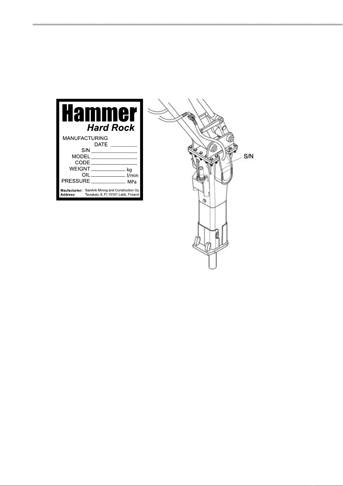
2.1 MODEL AND SERIAL NUMBER
The equipment serial number is stamped on the valve body. The model andserial number are also located
on the CE marking. Check that the model cor-responds to the one given on the cover of this manual.
It is important to make correct reference to the serial number of the attach-ment when making repairs
or ordering spare parts. Identication of the serialnumber is the only proper means of maintaining and
identifying parts for aspecic product.
MACHINE NUMBERS
7
PRODUCT INTRODUCTION
3. PRODUCT INTRODUCTION
3.1 OVERVIEW
The product is a hydraulically operated breaker. It can be used on any carrier which meets the necessary
hydraulic and mechanical installation requirements. The unit functions by repeatedly raising a steel piston
anddriving it down onto the head of a removable breaking tool.
No additional pressure accumulators are necessary since the integratedpressure accumulator absorbs
hydraulic pressure peaks. The impact energy of the hammer is almost constant and independent of the
carrier’s hydraulic system.
3.2 REMOVAL FROM PACKAGE
Remove all the steel belts from the package. Open the package and removeall plastics covering the
product. Recycle all package materials (steel, plastic, wood) properly.
Check that the product is in good condition and that there is no visible dam-age. Check that all ordered
parts and accessories have been enclosed withthe product. Some options may be provided by your local
dealer like instal-lation kits; including hoses and mounting bracket.
3.3 LIFTING INSTRUCTIONS
Use a hoist when lifting components which weigh 23 kg or more, to avoidback injury. Make sure all
chains, hooks, slings etc., are in good conditionand are in the correct capacity. Be sure hooks are positioned
correctly. Lift-ing eyes are not to be side loaded during a lifting operation. Do not use thehammer’s tools
for lifting.

8
PRODUCT INTRODUCTION
3.3.1. PROVIDED LIFTING POINTS
The lifting eyes located on the Product housing are to be used solely to liftor handle the Product itself.
The lifting capacity calculation is based on Product’s working weight including normal working tool and
average sizedmounting bracket.
Warning! To avoid falling objects, do not use Product to lift other products. The lifting eyes located
on the Product housing are to be usedsolely to lift or handle the Product itself.
The maximum allowed total weight is shown on the Product’s CE-plate andspecication page. See
“Hammer specications”. If the weightexceeds the maximum allowed total weight shown on the CE-plate
andspecication page, you have to use other lifting points/methods than origi-nally provided on the
Product.
The other treaded holes on the Product (for example on the hammer powercell) are intended for
handling single parts only. It is forbidden to lift the en-tire assembly by using these threaded holes (for
example on the cylinderouter surfaces). For handling the parts, see product workshop documentation for
suitable lifting methods and lifting adapters.
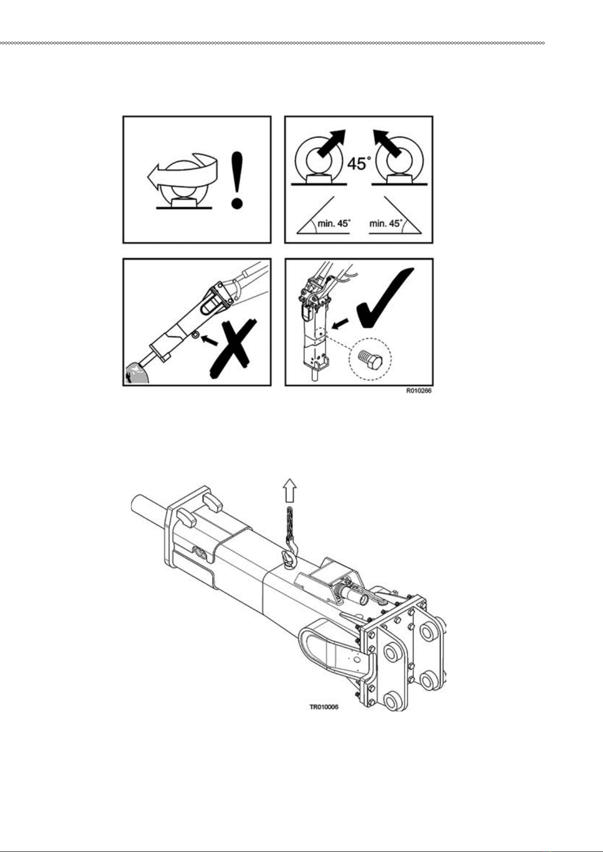
LIFTING EYE SCREWS
Lifting eye screws shall be completely tightened. The lifting eye must beloaded only if the screw is
properly tightened to the housing.
Warning! Failure to properly tighten the screw before allowing load pressure onthe lifting eye may
cause lifting eye to break and free fall of the Product.
If you use mechanical tools for tightening, make sure not to overstrain theshank. Before lifting make sure
that the rope and/or hook is stretched.
When two lifting eye screws are used, the lifting capacity depends on the angle of the lifting chains. The
angle should not be less than 45, as shown inthe illustration. When the lifting eye screws are tightened,
both rings shouldbe aligned.
The loading capacity calculation applies to temperatures between -10Cand 40 C.
Before reuse of lifting eye screws make sure there are no surface aws (forexample pits, voids, folds and
seams, deformation of the ring, missing orbroken threads, rust, etc.).
The local, national safety standards for machines and lifting-tackles must always be strictly observed.
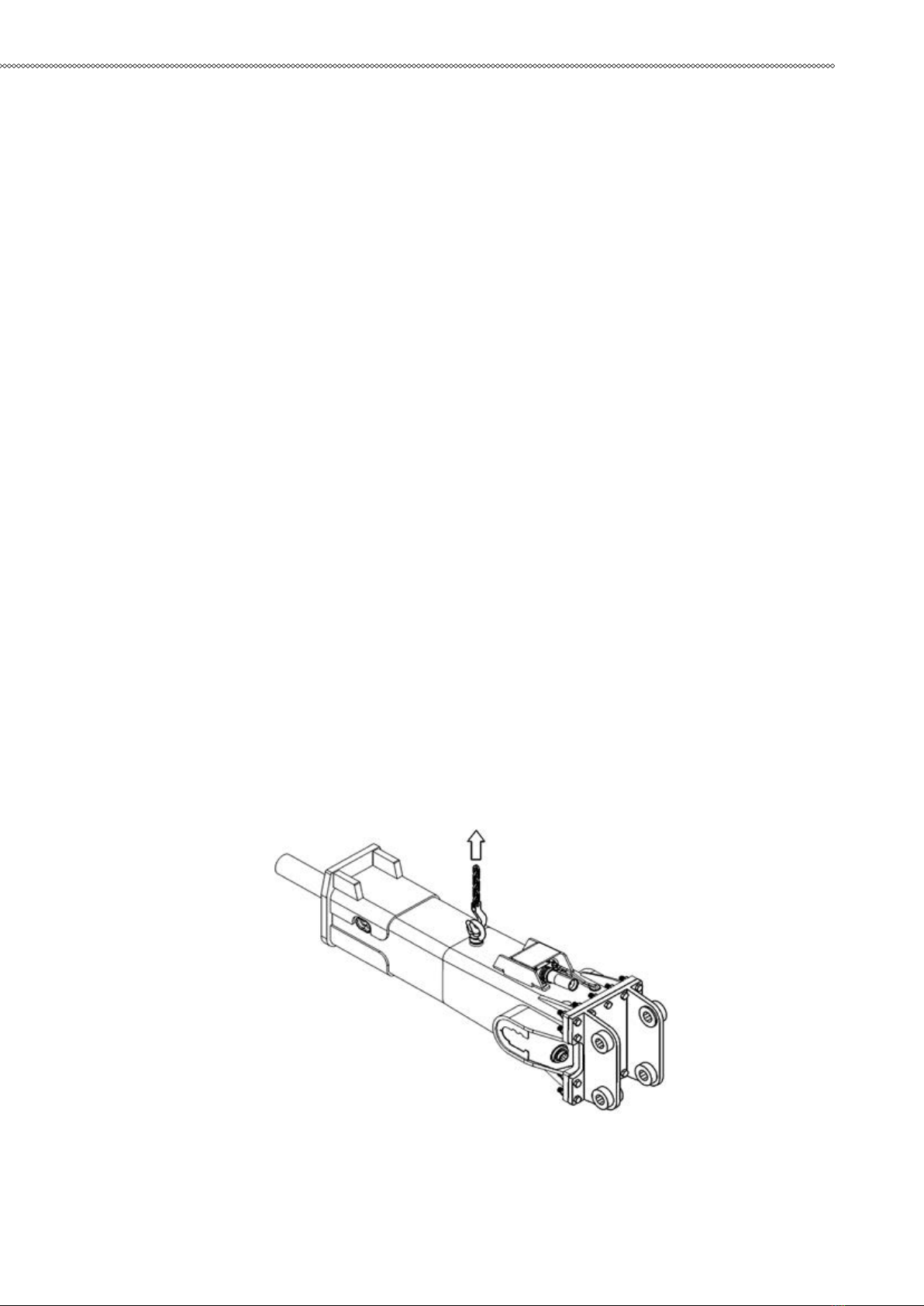
Note:The lifting eye must always be removed from the hammer and replaced with a blanking screw
before starting to operate hammer.
Lifting devices must safely carry the working weight of the product. See“Hammer specications”. Place
chains or slings, as shown bythe illustration, to lift the product.
Note: The lifting eye must always be removed from the hammer an
9
PRODUCT INTRODUCTION

10
3.4 SAFETY INSTRUCTIONS FOR LIFTING
Below are some common safety instructions concerning lifting operations.In addition to this, the local,
national standards for machines and lifting-tackles must always be strictly observed. Please Note that the
list below is notall inclusive, you must always ensure the procedure you choose is safe foryou and others.
■Do not lift load over people. No one shall be under the hoisted load.
■Do not lift people and never ride the hoisted load.Keep people clear from lift area.
■Avoid side pull of the load. Make sure you take up the slack slowly. Startand stop carefully.
■Lift load a few centimeters and verify it before proceeding. Make sure theload is well balanced. Check
for any loose items.
■Never leave the suspended load unattended. Maintain load control at alltimes.
■Never lift the load over the rated capacity (see product’s operatingweight from specication page).
■Inspect all lifting equipment before use. Do not use twisted or damagedlifting equipment. Protect
lifting equipment from sharp corners.
■Obey all local safety instructions.
PRODUCT INTRODUCTION
11
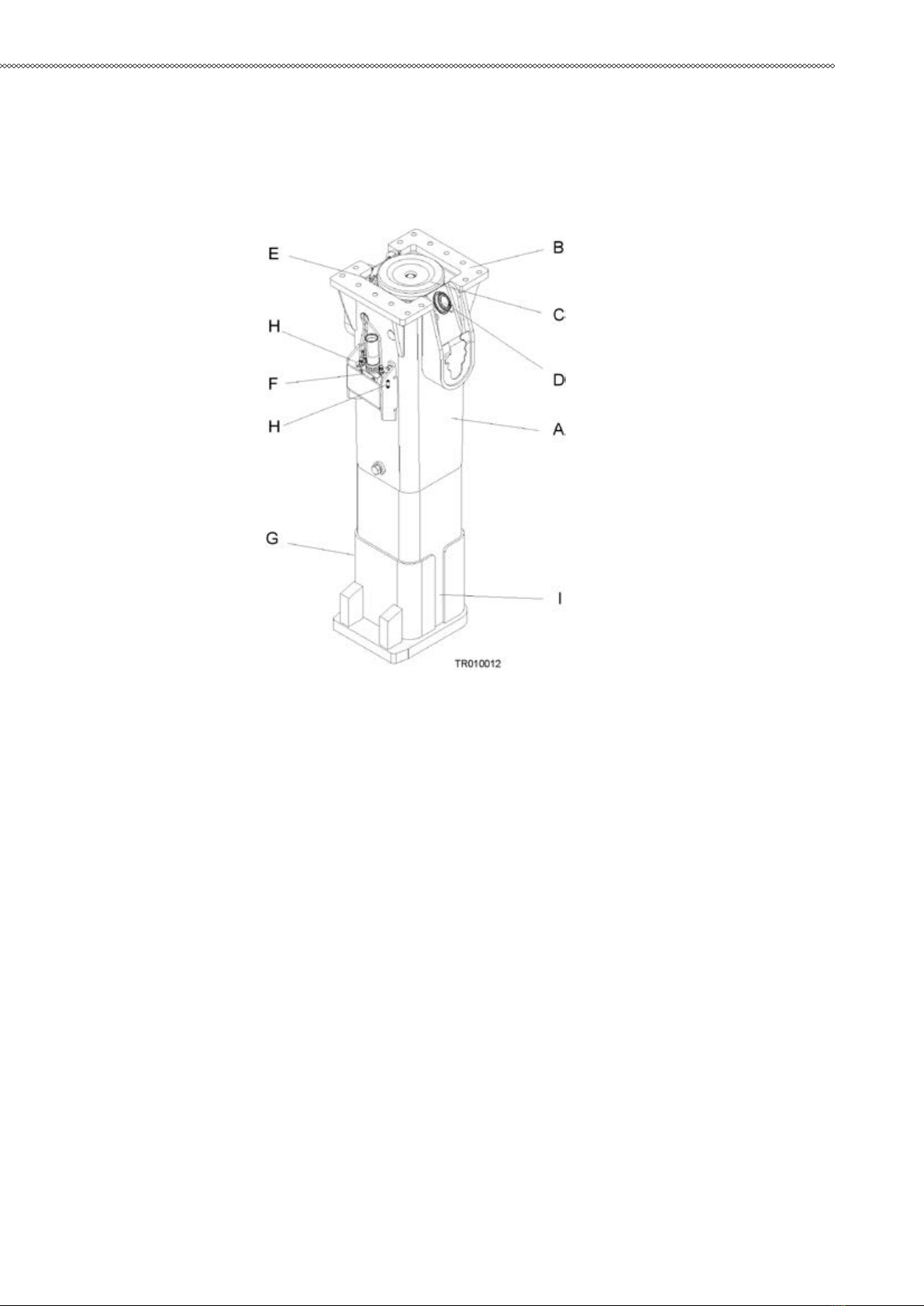
3.5 MAIN PARTS
The main parts of the hammer are shown below.
A. Housing
B. Mounting ange
C. Vibration dampening elements
D. Hose connections (pressure and return lines)
E. Pressure accumulator
F. Greasing device
G. Tool retaining mechanism
H. Grease nipple
I. Wear plates
PRODUCT INTRODUCTION
12
4. SAFETY
4.1 GENERAL SAFETY
All mechanical equipment can be hazardous if operated without due care orcorrect maintenance. Most
accidents involving machine operation andmaintenance are caused by failure to observe basic safety rules
or precautions. An accident can often be avoided by recognizing potentially hazardous situations before
an accident occurs.
Because it is impossible to anticipate every possible circumstance thatmight involve a potential hazard,
the warnings in this guide and on the machine are not all inclusive. If a procedure, tool, working method or
operatingtechnique not specically recommended by manufacturer is used, you mustsatisfy yourself that
it is safe for you and others. You should also ensure thatthe product will not be damaged or made unsafe
by the method of operationor maintenance procedures you choose.
Safety is not just a matter of responding to the warnings. All the time you areworking with your
attachment you must pay attention to what hazards theremight be and how to avoid them. Do not work
with the product until you aresure that you control it. Do not start any job until you are sure that you
andthose around you will be safe.
!Warning! Read the following warning messages carefully. They tellyou of dierent hazards
and how to avoid them. If proper precautionsare not taken you or others could be seriously injured.
4.2 SAFETY INSTRUCTIONS
MANUALS
Study this manual before installing, operating or maintaining the product. Ifthere is anything you don’t
understand, ask your employer or your local dealer to explain it. Keep this manual clean and in good
condition.
Study also the operating and maintenance manual of your carrier before operating the attachment.
CARE AND ALERTNESS
All the time you are working with the product, take care and stay alert. Always be alert for hazards. The
possibility of a serious or even fatal accidentis increased when you are intoxicated.
SAFETY

13
CLOTHING
You can be injured if you do not wear proper clothing. Loose clothing canget caught in the machinery.
Wear protective clothing to suit the job.
Examples are: a safety helmet, safety shoes, safety glasses, wellttingoveralls, earprotectors and industrial
gloves. Keep cus fastened. Do notwear a necktie or scarf. Keep long hair restrained.
PRACTICE
You and others can be killed or injured if you perform unfamiliar operationswithout practising them rst.
Practice away from the job site, in a clear area.
Keep other people away. Do not perform new operations until you are sureyou can do them safely.
REGULATIONS AND LAWS
Obey all laws, work site and local regulations which aect you and yourequipment.
COMMUNICATIONS
Bad communications can cause accidents. Keep people around you informed of what you will be doing.
If you will be working with other peoplemake sure they understand any hand signals you will be using.
Work sites can be noisy. Do not rely only on spoken commands.
WORK SITE
Work sites can be hazardous. Inspect the site before working on it.
Check for potholes, weak ground, hidden rocks etc. Check for utilities (electric cables, gas and water
pipes etc.). Mark the positions of underground cables and pipes if you will be breaking the ground.
Poor visibility can cause accidents and damage. Make sure that visibility andlightning of the working
area are adequate.
BANKS AND TRENCHES
Banked material and trenches can collapse. Do not work too close to banksand trenches where there
is a danger of collapse.
SAFETY BARRIERS
Unguarded equipment in public places can be dangerous. Place barriersaround the machine to keep
people away.
AIRBORNE POLLUTANTS
Airborne pollutants are microscopic particles, which will damage yourhealth, when inhaled. Aiborne
pollutants on construction sites can be e.g.silica dust, oil fumes or diesel exhaust particles, visible or
invisible. Especial-ly in demolition sites, there may be other dangerous substances, such ase.g. asbestos or
lead paints or other chemical substances.
The e˜ect of airborne pollutants may be immediate if the substance is poisonous. The main danger with
airborne pollutants comes from long term ex-posure, where particles are inhaled but not removed from
the lungs. Thedisease is called e.g. silicosis, asbestosis or other and will result in death orserious injury.
SAFETY
14
SAFETY
To protect yourself from airborne pollutants, always keep excavator doorsand windows closed during
operation. Excavators with pressurized cabinsshould be utilized in hammer operation. Proper maintenance
of fresh air lters of the excavator is essential. Where pressurized cabins are not available, proper respirators
must be utilized.
Stop working, when bystanders are in the area of airborne pollutants andmake sure they have proper
respirators. Respirators are as important for by-standers as hard hats.Respirators for both operator and
bystanders must beapproved by the respirator manufacturer for the application in question. It isessential
that the respirators protect from the tiny dust particles which causesilicosis and which may cause other
serious lung diseases. You should notuse the equipment until you are sure the respirators are working
properly.This means the respirators must be checked to make sure that it is clean,that its lter has been
changed, and to otherwise make sure the respiratorwill protect in the way it is meant to.
Always make sure dust has been cleaned o˜ your boots and clothes whenyou leave your shift. The
smallest particles of dust are the most harmful.They may be so ne that you can not see them. Remember,
you MUST pro-tect yourself and bystanders from the danger of breathing or inhaling dust.
Always follow local laws and regulations for airborne pollutants in the working environment.
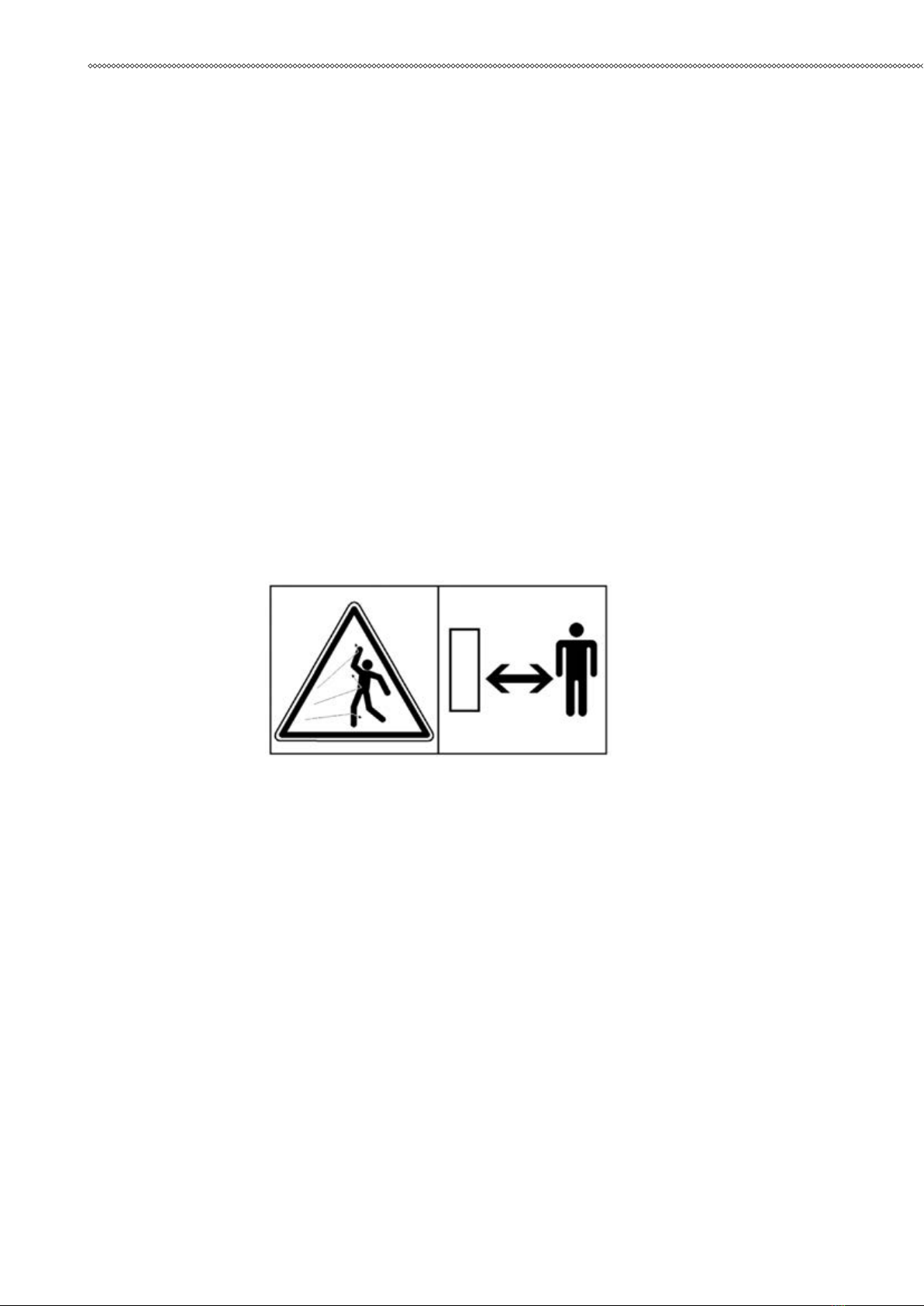
FLYING CHIPS OF ROCK
Protect yourself and your neighbourhood against ying chips of rock. Do notoperate the product or
carrier if someone is too close.
The European standard EN 474-1 on safety of earth-moving machinery requires that adequate operator’s
protection, such as bullet proof glass, meshguard or an equivalent protection is used.
Keep the cabin windows and doors closed during operation. Window barsare recommended to protect
the windows from ying chips of rock

15
SAFETY
HIGH NOISE LEVEL
Wear ear protection against high noise level to prevent personal injury.
EQUIPMENT LIMITS
Operating the product beyond its design limits can cause damage. It canalso be dangerous. See “Hammer
specications”.
Do not try to enhance the product’s performance by unapproved modica-tions.
HYDRAULIC FLUID
Fine jets of hydraulic uid at high pressure can penetrate the skin. Do notuse your ngers to check for
hydraulic uid leaks. Do not put your face closeto suspected leaks. Hold a piece of cardboard close to
suspected leaks andthen inspect the cardboard for signs of hydraulic uid. If hydraulic uid penetrates
your skin seek medical help immediately.
Hot hydraulic uid can cause severe injuries.
HYDRAULIC HOSES AND FITTINGS
Ensure all hydraulic components will withstand maximum pressure and mechanical stresses caused by
operation of the attachment. Consult your localdealer for instructions.
FIRE HAZARD
Most hydraulic uids are ammable and might ignite when contacting hotsurface. Avoid spilling
hydraulic uid to hot surfaces.
Working with the product on certain materials can cause sparks and hotsplinters to get loose. These can
ignite ammable materials around workingarea.
Ensure that adequate extinguisher is available.
HYDRAULIC PRESSURE
Hydraulic uid at system pressure can injure you. Before disconnecting orconnecting hydraulic hoses,
stop the carrier engine, operate the controls torelease pressure trapped in the hoses and wait ten (10)
minutes. During theoperation, keep people away from the hydraulic hoses.
There might be pressurized oil trapped inside the product even if it is discon-nected from the carrier.
Be aware of possible blank ring while greasing orremoving and installing hammer tools. See “Removal of
tool”.

16
SAFETY
PRESSURE ACCUMULATORS
The hammer incorporates one or two pressure accumulators, depending onthe model. The accumulators
are pressurized even when there is no hydraulic pressure to the hammer. Attempting to dismantle the
accumulators without rst releasing the pressure can cause injury or death. Do not try todismantle pressure
accumulators, contact your local dealer rst. See “Releasing hydraulic pressure from hammer”. See “Pressure
accu-mulator”.
LIFTING EQUIPMENT
You can be injured if you use faulty lifting equipment. Make sure that liftingequipment is in good
condition. Make sure that the lifting tackle complieswith all local regulations and is suitable for the job.
Make sure that the liftingequipment is strong enough for the job and you know how to use it.
Do not use this product or any of its parts for lifting. See “Lifting instructions”on page 9. Contact your
carrier dealer to nd out how to lift with your carrier.
SPARE PARTS
Use only genuine spare parts. Use only genuine tools with hydraulic hammers. The use of other spare
part or hammer tool brands may damage theproduct.
EQUIPMENT CONDITION
Defective equipment can injure you or others. Do not operate equipmentwhich is defective or has
missing parts.
Make sure the maintenance procedures in this manual are completed before using the product.
REPAIRS AND MAINTENANCE
Do not try to do repairs or any other maintenance work you do not understand.

17
SAFETY
MODIFICATIONS AND WELDING
Nonapproved modications can cause injury and damage. Contact your local dealer for advice before
modifying the product. Before welding on theproduct while it is installed on the carrier, disconnect the
carrier alternatorand battery. Note that welding of the hammer tools will render them uselessand make the
warranty void.
METAL SPLINTERS
You can be injured by ying splinters when driving metal pins in and out. Usesoftfaced hammer or drifts
to remove and t metal pins, such as pivot pins.Always wear safety glasses.

18
OPERATION
5. OPERATION
5.1. OPERATING INSTRUCTIONS
5.1.1 RECOMMENDED USE
The hammer is designed to be used in breaking oversized boulders, demolishing heavily reinforced
concrete structures and for major heavy excavationand clearing work. It can be also used for primary
breaking, tunnelling andremoval of metallurgical slag. Your local dealer will gladly give you more in-
formation.
5.1.2 OPERATING CONDITIONS
Principle of installation
Almost all carriers meeting mechanical and hydraulic requirements can beused to operate the
attachment. See “Hammer specications” .The product is installed on the carrier much in the same manner
as installinga bucket or other attachments. A ange mounted attachment requires a sep-arate mounting
bracket.
The attachment is connected to a carrier’s hydraulic circuit with an installation kit. If the carrier is already
equipped with an installation kit, the installa-tion requires only suitable hoses and ttings. If the carrier does
not havesuitable kit to run the attachment, one must be built. This may require morecomplex installation
including new piping and additional valves such as directional valve and pressure relief valve.
Suitable kits can be ordered from the manufacturer or local dealers, fromcarrier manufacturers and their
dealers or from third party suppliers.
Hydraulic oil
In general the hydraulic oil originally intended for the carrier can be usedwith this product. See
“Requirements for hydraulic oil”.
Operating temperature
The operating temperature is -20°C to 80°C. If the temperature is lowerthan -20°C, the hammer and
tool have to be preheated before any operations can begin, in order to avoid breaking the accumulator’s
membrane andthe tool. During operation they will remain warm. See “Preheating the hammer”.
Note: The temperature of the hydraulic oil must be monitored. Ensure thatoil grade and monitored oil
temperature together guarantee correct oil viscosity. See “Oil specications”.
Noise dampening
Operating the hammer near residential areas or ot her noise sensitive areas can cause noise pollution.
Inorder to avoid unnece ssary noise, please follow these basic rules:
1. When operating with the hammer, keep the tool at 90 degree angle to the material and t he feed force
inli ne with the tool.
2. Replace or x all parts that are worn out, damaged or l oosened. This not only saves your hammer but
it al so decreases the noise level.
19
OPERATION
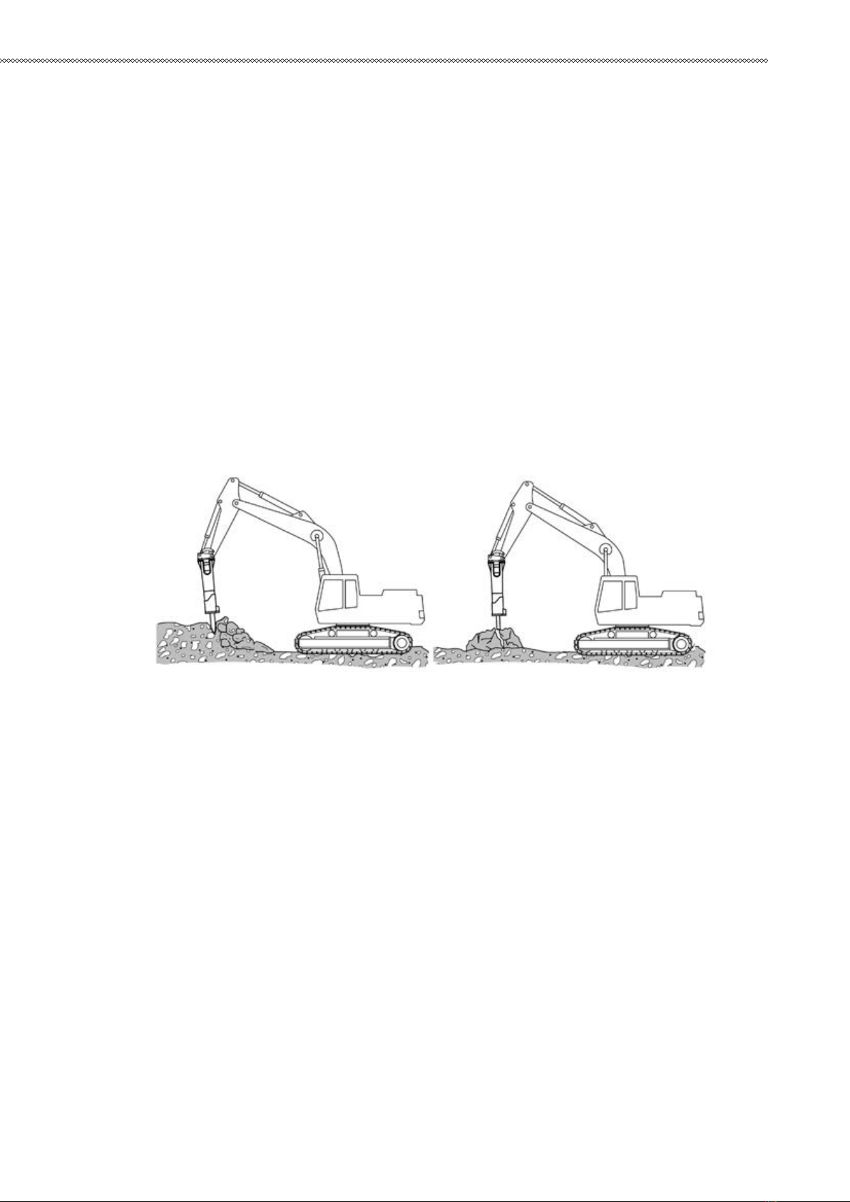
5.1.3 PRINCIPLES OF BREAKING
To increase the hammer’s working life, pay particular attention to correctworking methods and how to
choose the correct tool for the job. There areessentially two ways of breaking with a hydraulic hammer.
Penetrative breaking (or cutting)
In this form of breaking a moil point or chisel tool is forced inside the material. This method is most
eective in soft, layered or plastic, low abrasivematerial. The high impact rate of the small hammers makes
them ideal forpenetrative breaking.
Impact breaking
With impact breaking, the material is broken by transferring very strong mechanical stress waves from
the tool into the material. Impact breaking ismost eective in hard, brittle and very abrasive materials. The
high impactenergy of the big hammers makes them ideal for impact breaking. The bestpossible energy
transfer between the tool and the object is achieved with ablunt tool. The use of a chisel tool in hard
material will cause the sharp edgeto wear very quickly.
5.1.4 CHOOSING TOOLS
Chisel, moil point and pyramid
■ For sedimentary (e.g. sandstone) and weak metamorphic rock intowhich the tool penetrates.
■ Concrete.
■ Trenching and benching.
Blunt tool
■ For igneous (e.g. granite) and tough metamorphic rock (e.g. gneiss) intowhich the tool doesn’t
penetrate.
■ Concrete.
■ Breaking boulders.
It is important to choose a tool, which is suitable for your hammer and for theapplication you are
working on. The tool selection available depend on ham-mer model. See “Tool specications”.
20
OPERATION
5.1.5 IDLE SELECTOR
The hammer includes idle stroke preventing system as a standard feature.Frequent idle strokes have
a deteriorating eect on the hammer. Idle strokepreventing system can be turned ON or OFF by the
operator.
Idle selector can be used to warm up the hammer and oil before operation.
See “Operating conditions”. See “Requirements for hydraulic oil”.
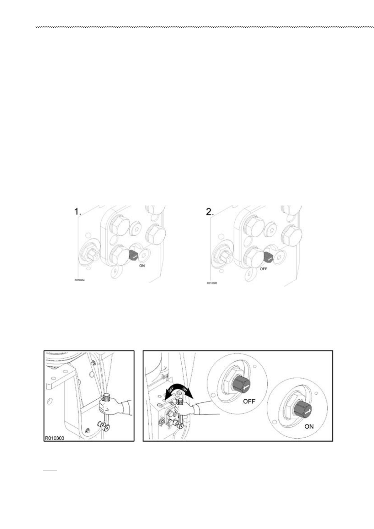
Idle selector ON (factory setting)
It is recommended to keep the mechanism turned ON in normal hammerwork. In ON-position the idle
stroke prevention system is activated and itprevents idle strokes. See illustration 1. Note that the hammer
can be start-ed only after feeding the tool against object.
Idle selector OFF
Idle selector can be turned OFF when breaking very soft material or in dem-olition application where it
is dicult to apply enough feeding force. See illustration 2.
5.1.6 ВTURNING IDLE SELECTOR ON AND OFF
1. Remove shield plate.
2. Turn the screw clockwise (to ON-position) or counter-clockwise (to OFF-position) as shown in illustration
below.
3.Insert shield plate.
Note:Idle selector has only two positions, ON and OFF. Do not apply anyother positions in between.
Table of contents
Other Hammer Power Tools manuals


