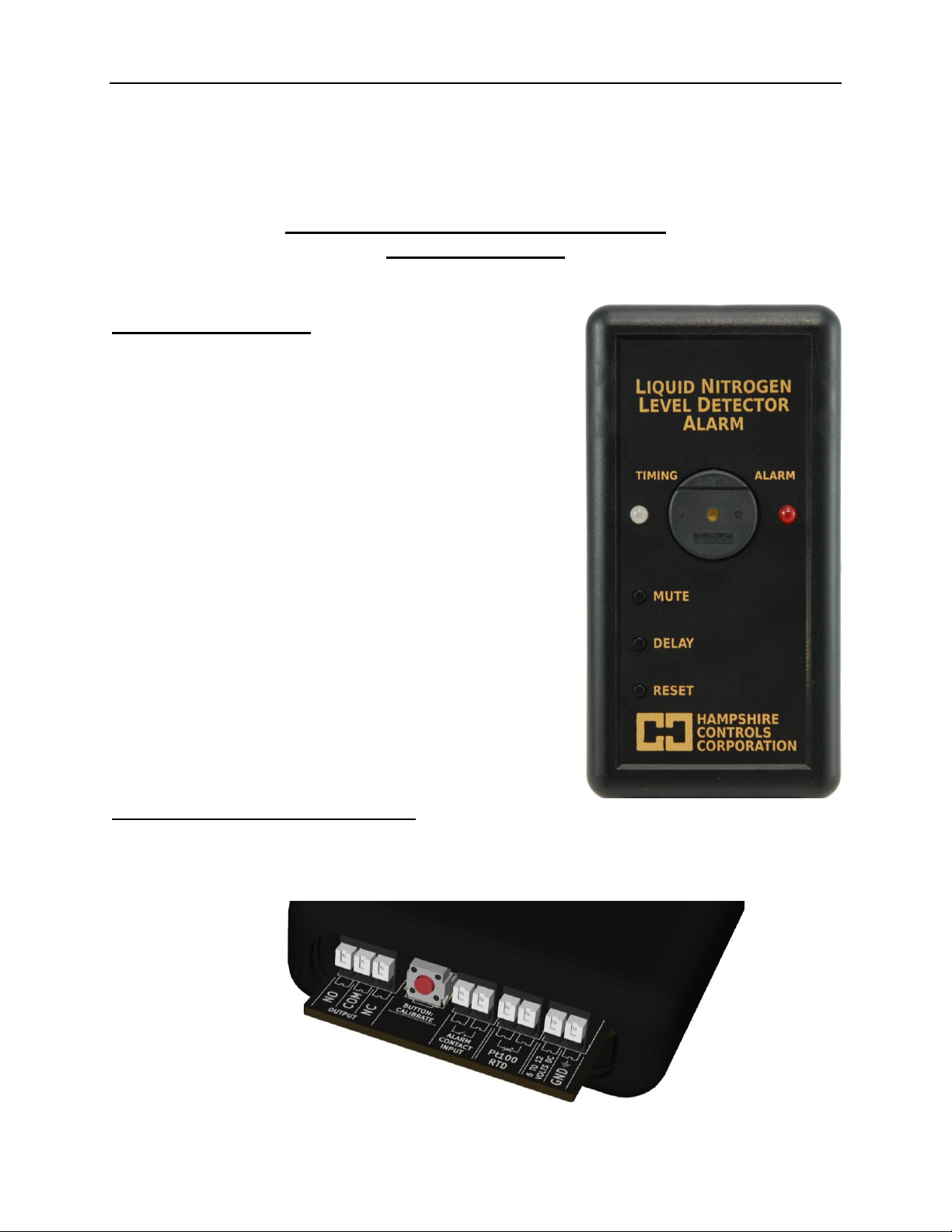
Hampshire Controls LD-215 User manual

Hampshire Controls Corp.
1 Grove St.
Dover, NH 03820
(603) 749-9424 or Toll Free US/Canada (866) 496-9424
www.hampshirecontrols.com
LD-215 Liquid Nitrogen Level Sensor
User Instructions
Overview of Operation
The LD-215 uses a cryogenic RTD to sense the surface of
liquid nitrogen by monitoring the self-heating of the probe. The
alarm will sound and the output relay will change state when the
liquid level drops below the probe tip. In reverse mode, the
alarm will sound and the output relay will change state if the
liquid level makes contact with the probe tip.
The alarm can be silenced for a selectable period of time by
pressing the “MUTE”button. During mute the “ALARM”LED
will continue to flash and the output relay will stay in the “alarm”
condition. A return to normal liquid level will clear the alarm. See
page 2 for mute duration adjustment.
An alarm delay can also be specified. After the unit recognizes
an alarm condition, the green status “TIMING”LED will switch to
yellow and the unit will delay for the selected period before
alarming. See page 2 for alarm delay adjustment.
Any alarm condition, muted or not, will cause the relay to switch
to alarm state. The user can wire to the “Normally Open” (NO,
closed on alarm) or “Normally Closed” (NC, open on alarm)
contacts for external dialers, or other functionality.
Setting the Trip Point (Calibration)
Make sure the probe tip is fully submerged in liquid Nitrogen, wait 2 minutes for the probe temperature to
fully stabilize, press the RED push-button twice (pictured below). Observe the “TIMING” LED flash green
7 times to confirm successful setting of the new setpoint.

- 2 -
Setting the Mute and Delay Periods
Setting
Value
Mute
Time (min)
To set the mute time, hold the “MUTE” button until the “ALARM” LED
begins a quick flash sequence. After the LED goes out, tap the “MUTE”
button the desired setting count, between 1 and 6 taps, after a pause the
“ALARM” LED will flash the new setting. A single long pulse signifies a
failure to change.
To determine the current mute setting, tap the “MUTE” button. The
“ALARM” LED will blink the current setting.
1
5
2
10
3
15
4
20
5*
30
6
60
Setting
Value
Delay
Time (min)
To set the delay time, hold the “DELAY” button until the “ALARM” LED
begins a quick flash sequence. After the LED goes out, tap the “DELAY”
button the desired setting count, between 1 and 6 taps, after a pause the
“ALARM” LED will flash the new setting. A single long pulse signifies a
failure to change.
To determine the current delay setting, tap the “DELAY” button. The
“ALARM” LED will blink the current setting.
1*
0
2
0.5
3
1
4
5
5
10
6
30
* = defaults
External Connections
All external connections, and one push button switch, are on the bottom rear of the case, shown above.
Pushing the white button on the connector opens the gate to accept a wire. Release the button to close.
From left to right, the functions are:
NO, COM, NC: Relay output, single pole, double throw (SPDT), for connection to a remote alarm
or monitoring system. The COM/NO pair close on alarm, the COM/NC pair open on alarm.
RED BUTTON: Used to set the probe calibration, once probe is submerged for 2 minutes; push
this button twice to set calibration.
ALARM CONTACT INPUT: Add a jumper to this pair of contacts to reverse the alarm function
(Rarely used, high-level alarm).
Pt100 RTD: Input for LD-215 sensor, polarity is not important, factory installed.
6 TO 12 VOLTS DC:Positive (+) connection to power supply, factory connected.
GND: Negative (-) connection to power supply, factory installed.

- 3 -
Battery
Insert the included batteries in the compartment at the back of the unit, please note the polarity.
The LD-215 uses two rechargeable 1.2V NiMH AA cells for backup, and can run more than 24 hours on
battery power. The batteries are continuously charged while the device is powered by the AC adapter. If
AC power is lost for an extended period and the batteries state-of-charge becomes too low, the LD-215
will alarm. The low-battery alarm is indicated by a repeating pattern of two fast beeps followed by a
pause.
NiMH rechargeable batteries must be used. If replacement is necessary please contact the factory.
First Use
Plug the power supply into an AC outlet and insert the rechargeable batteries.
Push the RESET button to clear the program.
Put the tip of the probe into the liquid Nitrogen to be monitored, height adjustment is available by
using the supplied Allen-wrench to adjust the shaft collar, up or down, on the probe.
After an initial beep the “TIMING”LED should blink green (if it blinks yellow go to page 1 “Setting
the Trip Point”). Test the installation by sliding the probe up until it is no longer submerged.
The “TIMING”LED will start to blink yellow within 10 seconds. This indicates that the probe is
registering an alarm level.
After the alarm-delay period, the red “ALARM”LED will blink, and the beeper will sound and the
output relay will change state.
Care and Maintenance
The LD-215 case can be cleaned with a soft dry cloth. Avoid harsh chemicals including alcohols as they
may permanently mar the case surface.
Periodically inspect the probe and power supply cables and connections for damage. Although the probe
cable is jacked in PTFE (Teflon®), a highly resilient plastic, the temperature of liquid nitrogen does cause
the material to stiffen. AVOID quickly flexing any cable that has been directly exposed to LN2 liquid until
it has time to warm up.
The LD-215 should be recalibrated periodically as electronic device parameters may drift over time.
Simply follow the instructions found on the first page in the section titled “Setting the Trip Point”. After
recalibrating, pull the probe tip up out of the liquid (one inch or less above the surface) and wait for the
device to alarm. Verify that the “ALARM” LED flashes, the beeper sounds, and the relay changes state.
To avoid a lengthy wait, you may want to set the alarm delay to zero before the test and then return it to
the desired setting when complete.
The batteries may be tested periodically by unplugging the power supply and allowing the unit to run on
battery power for 5-10 minutes. If the LD-215 fails to operate, or if the low battery alarm activates, the
batteries should be replaced. The batteries should be replaced every 3-5 years.
Table of contents