bend the Pilot Inlet Tube e. Before reattaching the Burner Assembly, blow out all
water from the Pilot Inlet Tube, Air-Intake Adjustment q, Burner Tube rand the
Pilot Light 2. Make sure that the “O” Ring for the Pilot Inlet Tube is replaced if it
was removed.
CAUTION: DO NOT submerge the Valve Housing 7in water. Water will prevent
gas from freely passing through the housing into the Burner Assembly 5and
the flame may be erratic or extinguished and release gas into the room. Keep
the orifice of the Gas Nozzle =open and free of wax. If necessary, remove the
Gas Nozzle with 9/16” wrench, then clean it with hot water.
If Gas Odor Is Detected
See Figure 2 on previous page. An unlit Pilot Light 2can allow gas to accumulate
in the room when the unit is left with the gas supply turned on. If the Pilot Light fails
to stay lit, adjust it to a larger flame, or eliminate the draft blowing it out.
Leakage will result if the “O” Ring wis missing. Check to verify the “O” Ring is
installed if the leak occurs following cleaning or disassembly for other reasons.
If gas leakage is noted at the Gas Adjustment Thumbscrew 8or at the Gas Nozzle
=, gently tighten the parts with a wrench to snugly seal them against the body of
the Valve Housing 7. Do not over tighten, this may cause damage to the housing
itself.
If leakage continues after securely tightening the Gas Nozzle =, or if the burner
flame fails to shut off automatically when ON-OFF Platform 9is released, return
the Touch-O-Matic®bunsen burner to Whip Mix for repair.
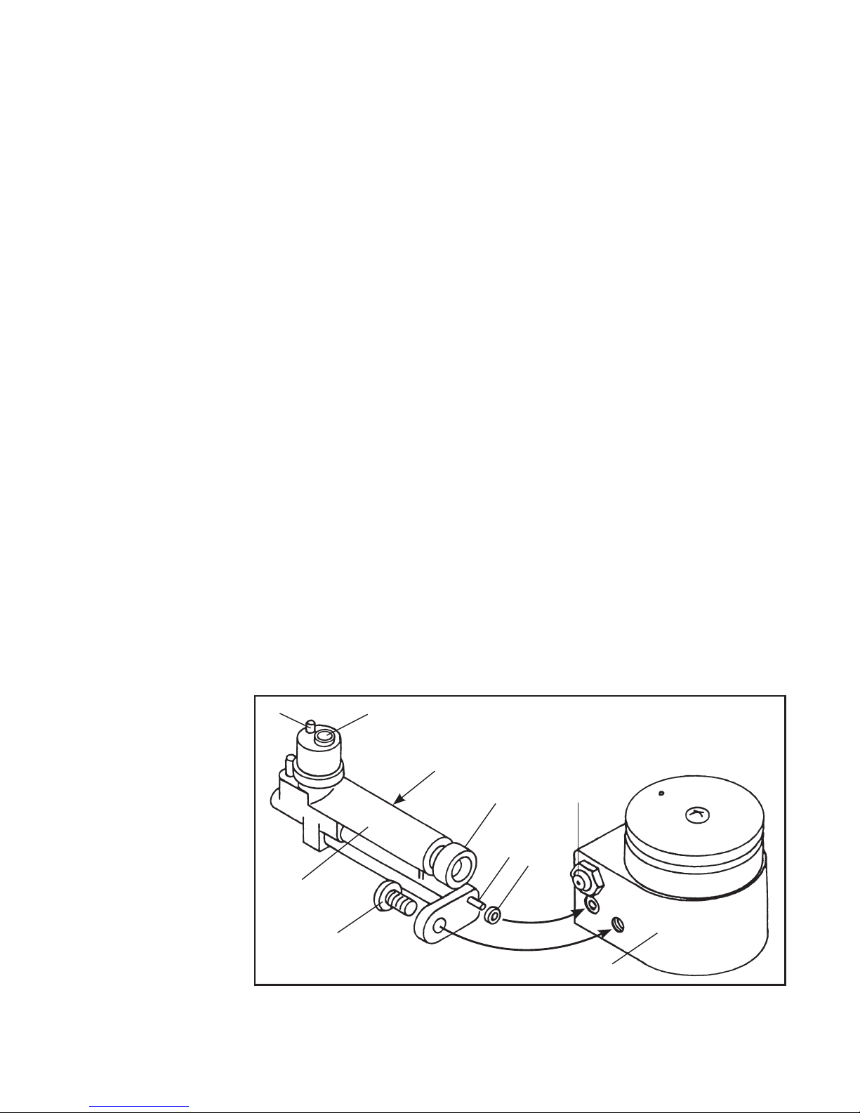
Use of Waxing Cup and
Loop Heat Conductor
The Waxing Cup tand the Loop Heat
Conductor yare optional accessories.
Remove the Pilot Shield 1and
connect the small loop built into the
outer circumference of the Waxing Cup
over the Post for the Waxing Cup 3.
The Loop Heat Conductor is placed
into the Waxing Cup, circular side
down, and the Loop Heat Conductor
Stem uis positioned above the
Pilot Light, or main burner, flame to
transfer heat down into the wax cup for
softening and keeping wax at a desired
consistency. Replace the Pilot Shield
after attaching the Waxing Cup.
1
y
t
3
u
Figure 3: Use of Waxing Cup
and Loop Heat Conductor
R
O
T
A
T
E