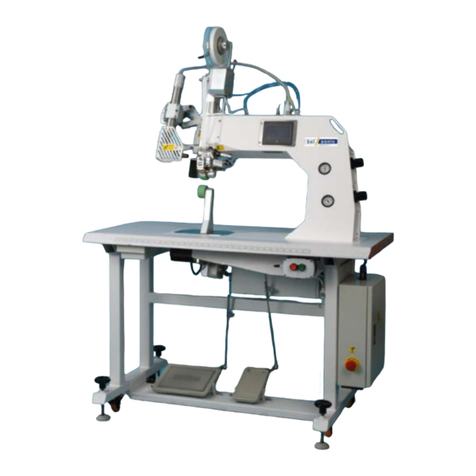
H&H US-511 User manual

US-511 operation manual
issue 1 20.07.27 display version 6 . plc controller version 6P. 1 of 22
Content
> Precautions with Regard to Safety.......................................................................................2
> Name Plate ..................................................................................................................................3
> Introduction ................................................................................................................................4
> Specifications.............................................................................................................................5
> Features .......................................................................................................................................6
> Component Names ................................................................................................................... 7
> Principle of Seam Sealing....................................................................................................... 8
> Preparation for Installation..................................................................................................... 9
> Selection and Replacement of Cutter Wheel ...................................................................10
>> Selection of the cutter wheel ....................................................................................10
>> Replacement of the Cutter Wheel............................................................................10
>Operation and Controls ......................................................................................................... 11
>> Touch Screen Control................................................................................................. 11
>> Main Page ...................................................................................................................... 12
>> Parameter.......................................................................................................................13
>> Fixed Length Mode...................................................................................................... 15
>> Monitor............................................................................................................................16
>> Maintenance ..................................................................................................................17
>> Program Version .......................................................................................................... 18
>> Language .......................................................................................................................19
> Maintain...................................................................................................................................... 20
> Appendix A . Pneumatic Scheme........................................................................................21
> Appendix B . Wiring Scheme ...............................................................................................22

US-511 operation manual
issue 1 20.07.27 display version 6 . plc controller version 6P. 2 of 22
> Precautions with Regard to Safety
Please observe these safety tips for safe, efficient, and injury-free operation of your equipment. By
strictly following all instruction contained in this manual you will certainly obtain an excellent
performance from the use of this equipment for many years.

US-511 operation manual
issue 1 20.07.27 display version 6 . plc controller version 6P. 3 of 22
> Name Plate
Figure 1 Name Plate

US-511 operation manual
issue 1 20.07.27 display version 6 . plc controller version 6P. 4 of 22
> Introduction
Thank you for your choosing of US-511 which is manufactured by H&H.
The US-511 ultrasonic rotary welding machine was specially designed for cutting and welding
different type of fabric. Various operations such as “line bonding”, anti-fray cutting, button hole
opening can be carried out using US-511.
In order to fully understand how to use this machine properly, and avoid damage to both the machine
and operating personnel, please read this manual carefully and keep it safe for future reference.

US-511 operation manual
issue 1 20.07.27 display version 6 . plc controller version 6P. 5 of 22
> Specifications
Model : US-511
Voltage : 220 V, Single Phase
Frequency : 50/60 Hz
Power Consumption : 700 W
Compressed Air : 0.4~0.6 Mpa
Sonic Frequency : 28kHz
Overall Dimensions : 1200mm x 650mm x 1230mm (length x width x height)
Net Weight : 108 kg
Note : due to continuous improvement, specifications are subjected to change without prior
notification

US-511 operation manual
issue 1 20.07.27 display version 6 . plc controller version 6P. 6 of 22
> Features
Quiet ultrasonic system.
Microprocessor control with large panel touch screen operator interface.
Unique welding technique ensuring consistent welding energy control.
Precise timing control resulted in no marking, over welding and skip welding during start and stop
operation.
Excellent control in constructing curved seams.
3D seam construction.
Easy to adopt sewing machine platform.

US-511 operation manual
issue 1 20.07.27 display version 6 . plc controller version 6P. 7 of 22
> Component Names
13
3
4
1
5 6
12
11
10
9
7
8
15 14
16
2
Figure 2 Machine parts names
1. pressure adjusting knob 9. power switch
2. cylinder 10. pre-pressure (working pressure) gauge
3. cutter wheel 11. pre-pressure (working pressure) adjustment
knob
4. lower wheel 12. pressurized pressure gauge
5. pressure pedal 13. pressurized pressure adjustment knob
6. working pedal 14. supervisor control key
7. side pedal, control cutter wheel up and down 15. USB socket
8. electric box 16. touch screen

US-511 operation manual
issue 1 20.07.27 display version 6 . plc controller version 6P. 8 of 22
> Principle of Seam Sealing
Ultrasonic energy is a form of physical vibration. The commonly used vibration frequencies are 20kHz,
30kHz, 35kHz and 40kHz. Different materials exhibit different behaviors under ultrasonic vibration. Synthetic
material generates internal heat under ultrasonic vibration. The US-511 machine generates vibration on the
surface of the horn. Fabric with at least 50% synthetic material is placed on the surface of the horn. A special
tool called cutter bit is pressed against the horn so that fabric between the horn and the cutter bit is exposed
to vibration. The heat generated in the fabric portion under pressure is heated up instantly and the
temperature is high enough to melt the fabric, hence resulting in an ultrasonic cut.
US-511 is engineered to careful manage this vibrating energy in order to slice fabric consistently in single
layer or multi-layer application.
During single layer operation, fabric is melted and separated resulting in a fray free edge. While during
multi-layer operation, layers of fabrics are cut but at the same time the edges of the fabrics are melted and
fused together resulting in a “weld”. This process is sometimes referred as a “cut and seal” or “line bonding”
operation.

US-511 operation manual
issue 1 20.07.27 display version 6 . plc controller version 6P. 9 of 22
> Preparation for Installation
Installation must be carried out by authorized personnel. Follow the steps below:
1. Position the machine on a flat surface and allow at least 50cm clearance on both sides as well as
the back side, this is essential for the hot air ventilation and also to allow enough room for
maintenance personnel to carry out necessary service and maintenance.
2. Adjust the foot stand so that the machine is level and stable.
3. Loosen all packing cable ties and materials in order to free up all machine movements.
4. Connect the power plug to a suitable outlet with at least 10A capacity. Make sure grounded and
reliable.
5. Locate the air hose supplied with the machine. Connect one end to the inlet of the compressed air
water filter at the back side of the machine; connect the other end to a compressed air supply such
as air compressor or central air supply. Make sure the compressed air supply has at least 0.4Mpa (4
bar) of pressure.

US-511 operation manual
issue 1 20.07.27 display version 6 . plc controller version 6P. 10 of 22
> Selection and Replacement of Cutter Wheel
>> Selection of the cutter wheel
According to different fabrics and process, you can choose to buy a cutter wheel with different
angle. Straight knife is 0 degree angle knife. Normally, the straight knife is easy to cut the fabric, and the
cutting surface is smooth, but have small incision fusion point. The greater opposite blade angle, the
better incision adhesion will achieve. (as shown in Figure 3).
Figure 3
>> Replacement of the Cutter Wheel
Cutter wheel is a vulnerable product. When it is difficult to cut even the pressure is increased, or fusion
point becomes very large, you should replace the cutter wheel, otherwise, high work pressure will speed up
the mold wear.
Remove the three screws which fix the wheel, then you can change the cutter wheel (shown as figure
4).
Change the position of the gasket next to the cutter wheel can move the position of the cutter wheel.
The lower wheel must be adjusted at the same time once the position of the upper cutter wheel is changed.
Otherwise it will lead to different speed in upper and lower wheel which affecting the cutting effect.

US-511 operation manual
issue 1 20.07.27 display version 6 . plc controller version 6P. 11 of 22
fix screws
Figure 4
>Operation and Controls
>> Touch Screen Control
The 1st & 2nd pages are welcome note & program loading pages. It will show up once the
machine is powered on.
Figure 5 Greeting Figure 6 Loading

US-511 operation manual
issue 1 20.07.27 display version 6 . plc controller version 6P. 12 of 22
>> Main Page
The 3rd page of the panel is named “main” means it is the main control of the machine.
1
345
2
Figure 7 Main Page
1. Upper motor (cutter wheel) speed setting button & display.
2. Lower motor (lower wheel) speed setting button & display.
3. Reverse speed setting button & display.
4. Click to make the machine to reverse.
5. Turn to next page.

US-511 operation manual
issue 1 20.07.27 display version 6 . plc controller version 6P. 13 of 22
>> Parameter
The page after main page is “parameter” page, shown as figure 8.
1
2
3
5
6
8
10
4
7
9
Figure 8 Parameter Page
1. Wheel start delay time setting. The time from when the right pedal is depressed to when the
upper and lower wheels start to rotate. This setting aims to prevent poor cutting result
because the ultrasonic may not function immediately at the beginning.
2. Ultrasonic stop delay time setting. Time from when the right foot pedal is released to when
the ultrasound stops. This setting aims to prevent poor cutting result because the ultrasonic
may stop earlier than the upper and lower wheels at the end.
3. Micro reverse time setting.
4. Reverse speed setting.
5. Back to main page.
6. Pressure relief time setting. When pressing the left pedal to pressurize, the air pressure
needs to be converted from working pressure to pressurized pressure, pressure relief time
refers to the time from when the left pedal is depressed to when the working pressure relief
to zero.
7. Lower wheel location setting. The location of cutter wheel may need to be changed, the

US-511 operation manual
issue 1 20.07.27 display version 6 . plc controller version 6P. 14 of 22
lower wheel position must be changed at the same time. Otherwise it will lead to different
speed in cutter wheel and lower wheel which may affect the cutting effect.
8. Upper wheel pressurize speed setting. When processing fabric position such as bone
position, pressurize is needed. Then the cutter wheel working speed will change to this
speed instead of the speed set in main page during pressurizing.
9. Lower wheel pressurize speed setting. When processing fabric position such as bone
position, pressurize is needed. Then the lower wheel working speed will change to this
speed instead of the speed set in main page during pressurizing.
10. Turn to next page.

US-511 operation manual
issue 1 20.07.27 display version 6 . plc controller version 6P. 15 of 22
>> Fixed Length Mode
The page after parameter page is “fixed length mode” page, shown as figure 9.
1
2
4
5678
3
Figure 9 Fixed Length Page
1. Fixed length mode on/off button. When the fixed length mode is on, the mode with the status
“on” will be completed in order; when the fixed length mode is closed, the setting of fixed
length mode will not work.
2. Back to main page.
3. Ared dot indicates that the machine is performing a fixed length operation of mode 1,
and which mode the red dot follows indicates which mode is in progress.
4. Turn to next page.
5. Press to turn on/off the corresponding fixed length mode.
6. Press to preset the additional strokes of corresponding fixed length mode.
7. Press to preset the times of corresponding fixed length mode.
8. Display the number of completions of corresponding fixed length mode. When the
number is equal to the number of setting times, it will turn to zero.

US-511 operation manual
issue 1 20.07.27 display version 6 . plc controller version 6P. 16 of 22
>> Monitor
The page after fixed length mode page is “monitor” page, shown as figure 10.
1
2
Figure 10 Monitor Page
1. Back to main page.
2. Turn to next page.

US-511 operation manual
issue 1 20.07.27 display version 6 . plc controller version 6P. 17 of 22
>> Maintenance
When the supervisor control key is turned right, the page after monitor page is “maintenance” page,
shown as figure 11. When the supervisor control key is turned left, the maintenance page is hidden.
1
2
3
Figure 11 Maintenance Page-1
Figure 12 Maintenance Page-2
1. Parameter lock, different numbers represent different meanings. For details, press “?” to
view the corresponding numbers’ meanings, as shown in figure 12 “Maintenance Page-2”.
2. Back to main page.
3. Turn to next page.

US-511 operation manual
issue 1 20.07.27 display version 6 . plc controller version 6P. 18 of 22
>> Program Version
When the supervisor control key is turned right, the page after maintenance page is “program version”
page, shown as figure 13. When the supervisor control key is turned left, the page after monitor page is
program version page.
1
2
Figure 13 Program Version Page
It is an information page for your reference and we can use these data for future maintenance
usage.
1. Back to main page.
2. Turn to next page.

US-511 operation manual
issue 1 20.07.27 display version 6 . plc controller version 6P. 19 of 22
>> Language
The page after program version page is “language” page, shown as figure 14.
12
Figure 14 Program Version Page
1. You can change the language between English, Chinese and Vietnamese by pressing the
button #1.
2. Turn to next page (main page).
Table of contents
Other H&H Welding System manuals
Popular Welding System manuals by other brands

GYS
GYS TRIMIG 385-4S manual
Miller Electric
Miller Electric MT-24-12-1 owner's manual
Thermal Dynamics
Thermal Dynamics MERLIN 6000 Service manual
Thermal Dynamics
Thermal Dynamics CUTMASTER 60i operating manual
Parweld
Parweld XTT-200 DC P Operator's manual
Migatronic
Migatronic PILOT 2000 instruction manual

