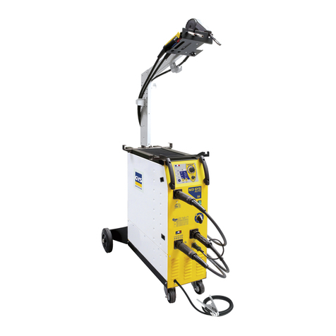
GYS TRIMIG 385-4S User manual

200710–S152- 75540
www.gys.fr
P : 10-17 / 43-48
P
: 18
-
25 / 42
-
48
P : 26-33 / 43-48
P : 34-48
P : 2- 9/ 43-48

2
MONTAGE
DESCRIPTION
100
kg
Tub capillair
Tub capillair
Gain téflon
Gain aci r
⑫
⑫⑫
⑫
①
①①
①
⑮
⑮⑮
⑮⑯
⑯⑯
⑯
②
②②
②
③
③③
③
④
④④
④
⑤
⑤⑤
⑤
⑥
⑥⑥
⑥
⑬
⑬⑬
⑬
⑦
⑦⑦
⑦
⑧
⑧⑧
⑧
⑨
⑨⑨
⑨
⑫
⑫⑫
⑫
⑩
⑩⑩
⑩

3
DESCRIPTION
Merci de votre choix ! Afin de tirer le maximum de satisfaction de votre poste, veuillez lire avec attention ce qui suit :
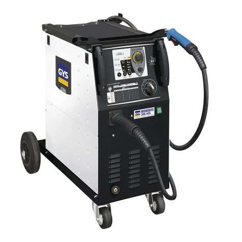
Le Trimig 3 5-4 S est un poste de soudure semi-automatique « synergic » sur roues, ventilé pour le soudage (MIG
ou MAG). Il est recommandé pour le soudage des aciers, des inox, des aluminums. Son réglage est simple et rapide
grâce à sa fonction « vitesse de fil synergique ». Il fonctionne sur une alimentation 400V triphasée.
ALIMENTATION ELECTRIQUE
Le courant effectif absorbé (I1eff) pour les conditions d'utilisation maximales est indiqué sur l'appareil. Vérifier que
l'alimentation et ses protections (fusible et/ou disjoncteur) sont compatibles avec le courant nécessaire en utilisation.
L'appareil doit être placé de façon telle que la fiche de prise de courant soit accessible.
Ne pas utiliser de rallonge ayant une section inférieure à 4 mm². Le TRIMIG 385-4S est livré avec une prise 32A
de type CEE 7/7. Il doit être relié à une prise 400V 3Ph. AVEC terre protégée par un disjoncteur 32A et un
différentiel 30mA.
DESCRIPTION DU POSTE
① Interrupteur marche – arrêt
② Réglage de puissance par 2 commutateurs (2 et 7
positions) permet d’ajuster la tension de soudage en
sortie de générateur. Le réglage de tension de sortie
est proportionnel à l’épaisseur du matériau à souder.
(cf page 6)
③ Clavier de réglages des paramètres de soudage
(mode manuel ou automatique).
④ Raccords torche au standard européen.
⑤ Voyant de protection thermique sur le clavier de
commande : signale une coupure thermique
lorsque l’appareil est utilisé de façon intensive
(coupure de plusieurs minutes).
⑥ Support torches avant
⑦ Câble d’alimentation (5m)
⑧ Sortie pince de masse.
⑨ Support bouteilles (maxi une bouteille de
10m3).
⑩ Chaine de fixation pour bouteilles.
Att ntion : bi n fix r l s bout ill s
⑪ Support bobine Ø 200/300 mm.
⑫ Electrovanne torche.
⑬ Support cables arrière.
SOUDAGE SEMI-AUTOMATIQUE EN ACIER / INOX (MODE MAG)
Le Trimig 3 5-4S peut souder du fil acier et inox de 0, /1/1,2. (figure ⑮)
L’appareil est livré d’origine pour fonctionner avec du fil Ø 1 mm en acier( galets Ø 0, /1)
Lorsque vous utilisez du fil de diamètre 1 mm ; il convient d’utiliser une torche avec un tube contact de 1. Le galet
du moto-dévidoir est un galet réversible 0, / 1mm. Dans ce cas, le positionner de telle façon à lire 1 mm sur le flanc
visible du galet.
L’utilisation en acier ou inox nécessite un gaz spécifique au soudage argon + CO2 (Ar + CO2 ).La proportion de CO2
varie selon l’utilisation. Pour le choix du gaz, demander conseil à un distributeur de gaz. Le débit de gaz en acier se
situe entre et 12 L/min selon l’environnement et l’expérience du soudeur.
SOUDAGE SEMI-AUTOMATIQUE ALUMINIUM
Le Trimig 3 5-4S peut souder du fil aluminium de 1 mm et 1,2 mm. (figure ⑯)
Pour souder l’aluminium, il faut utiliser un gaz neutre: argon pur (Ar). Pour le choix du gaz, demander conseil à un
distributeur de gaz. Le débit du gaz se situe entre 15 et 25 L/min selon l’environnement et l’expérience du soudeur.
Ci-dessous les différences entre l’utilisation soudage acier et soudage aluminium :
-La pression des galets presseurs du moto-dévidoir sur le fil : mettre un minimum de pression afin de ne pas
écraser le fil.
-Tube capillaire : retirer le tube capillaire avant de connecter la torche aluminium avec une gaine en téflon.
-Torche : utiliser une torche spéciale alumimium. Cette torche possède une gaine téflon afin de réduire les
frottements.
- NE PAS coup r la Gain au bord du raccord ! cette gaine sert à guider le fil à partir des galets.(cf schéma ⑯)
Tube contact : utiliser un tube contact SPECIAL aluminium correspondant au diamètre du fil.
4
PROCEDURE DE MONTAGE DES BOBINES :
CLAVIER DE COMMANDE
:
①
①①
①
②
②②
②③
③③
③④
④④
④
⑤
⑤⑤
⑤
⑧
⑧⑧
⑧
⑨
⑨⑨
⑨
⑩
⑩⑩
⑩
⑪
⑪⑪
⑪
⑫
⑫⑫
⑫
⑬
⑬⑬
⑬
⑭
⑭⑭
⑭
⑥
⑥⑥
⑥
⑦
⑦⑦
⑦

5
PROCEDURE DE MONTAGE DES BOBINES ET DES TORCHES :
• Ouvrir la trappe du poste.
• Positionner la bobine en tenant compte de l’ergot d’entrainement ③ du support bobine.
• Régler le frein de la bobine ④ pour éviter lors de l’arrêt de la soudure que l’inertie de la bobine n’emmêle le fil.
De manière générale, ne pas serrer trop fort !
• Les galets moteur ⑨ sont des galets double gorge (Ø 0, / Ø 1 ou Ø 1/ Ø 1,2). L’indication qu’on lit sur le galet
est celle que l’on utilise. Pour un fil de Ø 1 mm, utiliser la gorge de Ø 1.
• Pour la première mise en service :
odésserrer la vis de fixation du guide fil ⑧
oplacer les galets
opuis positionner le guide fil ⑦ au plus près du galet mais sans contact avec ce dernier, puis resserrer la vis de
fixation.
• Pour régler la molette des galets presseurs ⑥ , procéder comme suit : desserrer au maximum, actionner le
moteur en appuyant sur la gâchette de la torche, serrer la molette tout en restant appuyé sur la gâchette. Plier
le fil en sortie de la buse. Mettre un doigt sur le fil plié pour l’empécher d’avancer. Le réglage du serrage est
bon lorsque les galets patinent sur le fil même si le fil est bloqué en bout de troche.
Réglage courant de la molette des galets ⑥ : graduation sur 3 pour l’acier et graduation sur 2 pour
l’aluminium.
RACCORDEMENT GAZ
Visser le mano-détendeur sur la bouteille de gaz. ①
Pour éviter toute fuite de gaz, utiliser les colliers fournis dans la boîte d’accessoires.
CHOIX DES BOBINES:
Configurations possibles :
Type fil Torche GAZ
Ø 300
X
Acier
Ø 200
X
INOX Ø 200
X
Argon +
CO2
Ø 300
X* Alu
AG5 Ø 200
X* Argon pur
CLAVIER DE COMMANDE :
En position 2T et 4T, 2 modes sont proposés pour faciliter le réglage du poste : MANUAL ou SYNERGIC.
Choix du mod d soudag ⑩
2T : soudage 2 temps
4T : soudage 4 temps
SPOT : fonction bouchonnage /spot,
Avec réglage du diamètre du point
Réglag d la vit ss fil ⑪
Potentiomètre d’ajustage de la vitesse du fil.
La vitesse varie de 1 à 22 m/minute.
Pot ntiomètr d réglag SPOT ⑫
Mod Manual ⑬
En mode manuel, la vitesse de dévidage du fil est
déterminée par l’utilisateur en ajustant le
potentiomètre ⑪.
Mod Syn rgic ⑭
Positionner le potentiomètre ⑪ au milieu de la zone
« OPTIMAL SYNERGIC »
Dans ce mode le poste détermine la vitesse de fil
optimale à partir de 3 paramètres :
Tension
Diamètre du fil
Nature du fil
Il est possible d’ajuster la vitesse du fil + / -.
*Prévoir gaine téflon
.
et tube contact spécial alu

6
MODE « SYNERGIC » :

7
MODE «MANUAL »
Pour régler votre poste procéder comme suit :
- Choisissez la tension de soudage à l’aide des 2 commutateurs 2/7 positions
exemple : Pour souder de l’acier 1 mm
- commutateur du haut sur A
- commutateur du bas sur 1
Pour souder de l’acier 10 mm
- commutateur haut sur B
- commutateur bas sur 7
- Ajustez la vitesse du fil à l’aide du potentiomètre.
Conseils
L’ajustement de la vitesse du fil se fait souvent « au bruit » : l’arc doit être stable et avoir très peu de
crépitement.
Si la vitesse est trop faible, l’arc n’est pas continu.
Si la vitesse est trop élevée, l’arc crépite et le fil a tendance à repousser la torche.
MODE « SYNERGIC »
Grâce à cette fonction, plus besoin de régler la vitesse fil.
-Positionner le potentiomètre vitesse fil au milieu de la zone « Optimal synergic »
-Sélectionner :
La nature du fil
le diamètre du fil
La puissance (2 commutateurs 2 et 7 positions en face avant)
Pour sélectionner la position adéquate en fonction de l’épaisseur à souder se référer
au tableau « mode synergic » de la page en vis à vis.
A partir de cette combinaison de paramètres, le Trimig 3 5-4 S détermine la vitesse de fil optimale et le poste
est pret à souder.Il est ensuite possible d’ajuster la vitesse fil si nécessaire en + ou en – grâce au
potentiomètre. Une mémorisation des dernières configurations de soudage est effectuée et réactivée à
chaque mise en route du poste (diamètre fil, nature fil, mode).
CONSEILS ET PROTECTION THERMIQUE
•Le trimig 3 5-4S ne doit pas être élingué par ses poignées, ses supports torches ou son plateau supérieur mais
par le dessous du poste.
•Respecter les règles classiques du soudage.
•Laisser les ouïes de l'appareil libres pour l’entrée et la sortie d’air.
•Laisser l’appareil branché après soudage pour permettre le refroidissement.
•Protection thermique : le voyant s’allume et la durée de refroidissement est de quelques minutes en fonction
de la température ambiante.
FACTEURS DE MARCHE & ENVIRONNEMENT D’UTILSATION
•Le poste décrit a une caractéristique de sortie de type "tension constante". Son facteur de marche selon la norme
EN60974-1 est indiqué dans le tableau suivant :
X / 60974-1 @ 40°C (T cycle = 10 min) I max 60% (T cycle = 10 min)
100% (T cycle = 10 min)
Trimig 3 5-45 S 25% @ 370 A 2 0 A 210 A
Note : les essais d’échauffement ont été effectués à température ambiante et le facteur de marche à 40 °C a
été déterminé par simulation.
•Ces appareils sont de Classe A. Ils sont conçus pour un emploi dans un environnement industriel ou
professionnel. Dans un environnement différent, il peut être difficile d’assurer la compatibilité électromagnétique,
à cause de perturbations conduites aussi bien que rayonnées. Ne pas utiliser dans un environnement comportant
des poussières métalliques conductrices.

ENTRETIEN
•L'entretien ne doit être effectué que par une personne qualifiée.
•Couper l'alimentation en débranchant la prise, et attendre l’arrêt du ventilateur avant de travailler sur
l'appareil. A l’intérieur, les tensions et intensités sont élevées et dangereuses.
•Régulièrement, enlever le capot et dépoussiérer à la soufflette. En profiter pour faire vérifier la tenue des
connexions électriques avec un outil isolé par un personnel qualifié.
•Contrôler régulièrement l'état du cordon d'alimentation. Si le câble d'alimentation est endommagé, il doit être
remplacé par le fabricant, son service après vente ou une personne de qualification similaire, afin d'éviter un
danger
SÉCURITÉ
L soudag MIG/MAG p ut êtr dang r ux t caus r d s bl ssur s grav s voir mort ll s. Protég z-
vous t protég z l s autr s.
R sp ct z l s instructions d sécurité suivant s
:
Rayonn m nts Vous protéger à l’aide d’un masque muni de filtres conformes EN 169 ou EN 379.
d l’arc :
Plui , vap ur d’ au, Utiliser votre poste dans une atmosphère propre (degré de pollution ≤ 3), à plat
humidité: et à plus d’un mètre de la pièce à souder. Ne pas utiliser sous la pluie ou la neige.
Choc él ctriqu : Cet appareil ne doit être utilisé que sur une alimentation monophasée à 3 fils avec terre.
Ne pas toucher les pièces sous tension.
Vérifier que le réseau d'alimentation est adapté au poste.
Chut s : Ne pas faire transiter le poste au-dessus de personnes ou d’objets.
Brûlur s : Porter des vêtements de travail en tissu ignifugé (coton, bleu ou jeans).
Travailler avec des gants de protection et un tablier ignifugé.
Protéger les autres en installant des paravents ininflammables, ou les prévenir de ne pas
regarder l'arc et garder des distances suffisantes.
Risqu s d f u : Supprimer tous les produits inflammables de l'espace de travail. Ne pas travailler en
présence de gaz inflammable.
Fumé s : Ne pas inhaler les gaz et fumées de soudage. Utiliser dans un environnement
correctement ventilé, avec extraction artificielle si soudage en intérieur.
Précautions Toute opération de soudage :
supplém ntair s : - dans des lieux comportant des risques accrus de choc électrique,
- dans des lieux fermés,
- en présence de matériau inflammable ou comportant des risques d'explosion,
doit toujours être soumise à l'approbation préalable d'un "responsable expert", et
effectuée en présence de personnes formées pour intervenir en cas d'urgence.
Les moyens techniques de protections décrits dans la Spécification Technique CEI/IEC
620 1 doivent être appliqués.
Le soudage en position surélevée est interdit, sauf en cas d'utilisation de plates-formes de
sécurité.
L s port urs d stimulat urs cardiaqu s doiv nt consult r un méd cin avant d'utilis r c s appar ils.
N pas utilis r l post pour dég l r d s canalisations.
Manipul r la bout ill d gaz av c précaution, d s risqu s xist nt si la bout ill ou la soupap d la bout ill
sont ndommagé s.

9
ANOMALIES, CAUSES, REMÈDES
SYMPTOMES CAUSES POSSIBLES REMEDES
Des grattons obstruent l’orifice. Nettoyer le tube contact ou le changer et
remettre du produit anti-adhésion.
Le débit du fil de soudage n’est
pas constant.
Le fil patine dans les galets. - Contrôler la pression des galets ou les
remplacer.
- Diamètre du fil non conforme au galet.
-Gaine guide fil dans la torche non
conforme.
Frein de la bobine ou galet trop
serré. Desserrer le frein et les galets Le moteur de dévidage ne
fonctionne pas.
Problème d’alimentation Vérifier que le bouton de mise en service
est sur la position marche.
Gaine guide fil sale ou
endommagée. Nettoyer ou remplacer. Mauvais dévidage du fil.
Frein de la bobine trop serré. Desserrer le frein.
Mauvais branchement de la
prise secteur. Voir le branchement de la prise et
regarder si la prise est bien alimentée
avec 3 phases.
Mauvaise connexion de masse. Contrôler le câble de masse (connexion
et état de la pince).
Pas de courant de soudage.
Contacteur de puissance
inopérant. Contrôler la gâchette de la torche.
Gaine guide fil écrasée. Vérifier la gaine et corps de torche.
Blocage du fil dans la torche. Remplacer ou nettoyer.
Pas de tube capillaire. Vérifier la présence du tube capillaire.
Le fil bouchonne après les galets.
Vitesse du fil trop importante. Réduire la vitesse de fil
Le débit de gaz est insuffisant.
Plage de réglage de 15 à 20 L / min.
Nettoyer le métal de base.
Bouteille de gaz vide. La remplacer.
Qualité du gaz non satisfaisante. Le remplacer.
Circulation d’air ou influence du
vent. Empêcher les courants d’air, protéger la
zone de soudage.
Buse gaz trop encrassée. Nettoyer la buse gaz ou la remplacer.
Mauvaise qualité du fil.
Utiliser un fil adapté au soudage MIG-
MAG.
Le cordon de soudage est
poreux.
État de la surface à souder de
mauvaise qualité (rouille, etc…) Nettoyer la pièce avant de souder
Tension d’arc trop basse ou trop
haute. Voir paramètres de soudage.
Mauvaise prise de masse. Contrôler et positionner la pince de
masse au plus proche de la zone à
souder
Particules d’étincelage
très importantes.
Gaz de protection insuffisant. Ajuster le débit de gaz.
Pas de gaz en sortie de torche Mauvaise connexion du gaz Voir si le raccordement du gaz à côté du
moteur est bien connecté.

10
ASSEMBLY
DESCRIPTION
⑮
⑮⑮
⑮⑯
⑯⑯
⑯
Capillar
Capillar
T flon sh athing
St l sh athing
100
kg
⑫
⑫⑫
⑫
①
①①
①
②
②②
②
③
③③
③
④
④④
④
⑤
⑤⑤
⑤
⑥
⑥⑥
⑥
⑬
⑬⑬
⑬
⑦
⑦⑦
⑦
⑧
⑧⑧
⑧
⑨
⑨⑨
⑨
⑫
⑫⑫
⑫
⑩
⑩⑩
⑩

11
DESCRIPTION
The Trimig 3 5-4 S is a semi-automatic welding unit; it is ventilated for semi-automatic welding (MIG or MAG) It
is capable of welding steel, stainless steel and aluminium, and with it's « synergic wire speed » function
adjustment is easy and fast. It works on a 400v Three-phase power supply.
ELECTRICITY SUPPLY
The absorbed current (I1eff) is indicated on the device, for use at maximum settings. Check that the power supply
and its protection (fuse and/or circuit breaker) are compatible with the current needed during use.
The device must be placed in such way that the power socket is always accessible.
Do not use an extension cord which has a wire section inferior to 4 mm².
The Trimig 3 5-4 S is supplied with a 32A plug type EEC7/7. It should be plugged in to a 400 V (3PH) power socket
WITH earth and protected by a circuit breaker (32A and 1 differential 30mA. )
DEVICE PRESENTATION
Switch On – Off
Power Settings - 2 switches with 7 positions : allows
adjustment of the welding voltage output. The
adjustment of the output voltage is proportional to the
thickness of the material to weld. (please refer to page
14)
Welding settings adjustment keyboard (manual or
automatic mode).
European standard torch connection.
⑤Thermal Protection light:
Informs when a short Cool-down period is necessary
following intensive use.
⑥ Torch support.
⑦ Supply Cable (5m).
⑧ Out Earth cable.
⑨ Gas bottle support (max 1 bottle of 10m3).
⑩ Fastening chain for bottles. Warning: fast n th
bottl s corr ctly.
⑪ Reel support Ø 300 mm/ 200mm.
⑫ Solenoid valve torch.
⑬ Torch Cable support .
SEMI-AUTOMATIC WELDING FOR STEEL / STAINLESS STEEL (MAG MODE)
The TRIMIG 3 5-4S can weld 0. /1/1,2 mm steel and stainless steel wires .(figure ⑮)
The device is capable of working with Ø 1 mm steel wire (roller Ø 0. /1.0)
If using Ø 1mm wire, you should us a torch with a contact tip of 1, and ensure that the reversible rollers in the
wire feeder are posititioned correctly (so that the writing that states “1mm” is visible when in place)
For Steel or Stainless Steel, you will need to use specific gas - Argon + CO2 (Ar + CO2). The proportion of CO2 will vary
depending on usage. The gas flow for steel is between and 12L / min depending on the environment and experience of the
welder. For the specific requirements, seek advice from your gas distributor.
SEMI-AUTOMATIC WELDING FOR ALUMINIUM (MIG MODE)
The TRIMIG 3 5-4S can weld 1mm & 1,2 mm aluminium wire ⑯
To weld aluminium, neutral gas “pure Argon” (AR) is required. When choosing gas, ask a gas distributor for advice. The gas
flow in aluminium should be between 15 and 25 L / min depending on the environment and experience of the welder.
Things to note when welding with Aluminium
- Set the pressure rollers of the wire feeder on the wire to minimum pressure so as not to pinch the wire
- Remove the capillary tube before connecting the aluminium torch
- When welding aluminium use a special aluminium torch with Teflon sheath to reduce friction.
Do not cut th sh ath n ar th conn ctor! It is used to guide the wire from the rollers. (See diagram ⑯ )
- Contact Tip: Use the specific Aluminium contact tip corresponding to the diameter of the wire.

12
PROCESS OF REELS ASSEMBLY :
SETTINGS KEYBOARD:
①
①①
①
②
②②
②③
③③
③④
④④
④
⑤
⑤⑤
⑤
⑧
⑧⑧
⑧
⑨
⑨⑨
⑨
⑥
⑥⑥
⑥
⑦
⑦⑦
⑦
⑩
⑩⑩
⑩
⑪
⑪⑪
⑪
⑫
⑫⑫
⑫
⑬
⑬⑬
⑬
⑭
⑭⑭
⑭

13
PROCESS OF REELS AND TORCHES ASSEMBLY
• Open the door on the product.
• Place the reel on the driving pin of the reel support
• Tighten the nut until the reel is secure to avoid the reel inertia tangling the wire when the welding stops. In a
general way, do not over-tighten.
• The wire feeder is a double groove rollers (Ø Ø 0, /1 or Ø 1/ Ø1,2). The visible diameter indicated on the roller
when fitted is the diameter currently in use. For a Ø 1 wire, use the Ø 1 groove.
• For the first use:
- Release the fixing screw of the wire guide
- Place the rollers
- Then place the wire guide as close as possible to the roller but without touching it, then tighten the fixing
screw.
• To set the adjusting knob of the pressing rollers ,proceed as follow: : loosen the knob fully, start the motor by
pressing the torch trigger, tighten the adjustment knob whilst pressing the trigger. Bend the wire where it comes out
of the nozzle and hold it in place to stop its progress. The setting is correct when the guide roller slides over the wire
even when it is blocked at the end of the torch. A common adjustment is the rollers command on the scale 3 for
steel and 2 for aluminum.
GAS COUPLING
Screw the regulator/flowmeter on the gas bottle. ⑬
To avoid gas leaks, use the collars provided in the accessories box.
CHOICE OF REELS:
Possible settings:
Wire Torch GAS
Ø 300 X
Steel Ø 200 X
Argon +
CO2
Stainless
Steel Ø 200 X
Ø 300 X*
Alu AG5 Ø 200 X*
Pur Argon
SETTINGS KEYBOARD:
In 2T or 4T position, 2 modes are proposed to ease the settings of the device: MANUAL or SYNERGIC.
W lding mod choic
2T : two-stage welding
4T: 4-stage welding
SPOT : Spot welding with adjustable spot
diameter
Wir sp d s ttings ⑪
Wire speed fitting potentiometer.
The speed varies from 1 to 22 m/minute.
SPOT pot ntiom t r fitting ⑫
Manual Mod ⑬
In manual mode, the wire speed is determinated by
the user by adjusting the potentiometer⑪.
Syn rgic Mod ⑭
Position the potentiometer ⑪ in the middle of
the« OPTIMAL SYNERGIC » zone
In this mode, the device determines the optimal wire
speed according to 3 parameters:
Voltage
Wire diameter
The power mode
It is possbile to adjust the speed wire + / -.

14
MODE « SYNERGIC » :

15
«MANUAL» MODE
To set your device, proceed as follows:
- Choose the welding voltage using the 2 power switches (2& 7 positions)
Example: For welding Steel - 1 mm
- Set the top switch to "A"
- Set the bottom switch to "1"
For welding Steel - 10 mm
- Set the top switch to "B"
- Set the bottom switch to "7"
- Adjust the wire speed with the potentiometer.
Advice
The wire speed adjustment is often determined « by the noise »: the arc must be stable and have a low
crackling.
If the speed is too low, the arc is not continuous.
If the speed is too high, the arc crackles and the wire pushes back the torch.
« SYNERGIC » MODE
This function automatically controls the wire speed. There is no need to set the wire speed manually.
Position the wire speed potentiometer in the middle of the« Optimal synergic » zone.
-Select:
Wire type
Wire diameter
Power mode (2 switches, 2 & 7 positions)
To select the right position in accordance with the thickness of the part to weld, please refer to
the “synergic mode” table on the previous page.
From the settings chosen, the Trimig 3 5-4S determines the optimum wire speed and the device is ready to
weld. It is also possible to adjust the wire speed if necessary by adjusting potentiometer + or – manually.
The last welding configuration is saved in the memory automatically (wire diameter, wire type, mode).
ADVICE & THERMAL PROTECTION
•The Trimig 3 5-4S should not be lifted by its handles, torch support, or the top of the machine. When lifting
the Trimig, nsur th w ight is fully support d at th bottom of th machin .
•Always respect the basic rules of welding.
•Do not block/cover the ventilation holes of the machine.
•Leave the device plugged after welding to allow it to cool.
•Thermal protection: If the machine becomes too hot, the warning light will illuminate and the machine will
stop. Cooling will take a few minutes, the length of time will also depend on the external temperature.
DUTY CYCLE & WELDING ENVIRONMENT IN USE
•The welding unit describes an output characteristic of "constant current" type. The duty cycles following the
standard EN60974-1 (at 40°C on a 10mn cycle) are indicated in the table here below:
X / 60974-1 @ 40°C (T cycle = 10 min) I max 60% (T cycle = 10 min)
100% (T cycle = 10 min)
Trimig 3 5-4S 25% @ 370 A 2 0 A 210 A
Note : The machines’ duty cycle has been tested at room temperature (40°C) and has been determined
by simulation.
•These are Class-A devices. They are designed to be used in an industrial or professional environment. In a
different environment, it can be difficult to ensure electromagnetic compatibility, due to conducted
disturbances as well as radiation.

16
MAINTENANCE / ADVICE
Maintenance should only be carried out by a qualified person.
Ensure the machine is unplugged, and that the ventilator inside has stopped before carrying out maintenance
work. (DANGER High Voltage and Currents).
GYS recommends removing the steel cover 2 or 3 times a year to remove any excess dust. Take this opportunity
to have the electrical connections checked by a qualified person with an insulated tool.
Regularly check the condition of the power supply cord. If damaged, it will need to be replaced by the
manufacturer, its’ after sales service or a qualified person.
Ensure the ventilation holes of the device are not blocked to allow adequate air circulation.
SAFETY
Arc w lding can b dang rous and can caus s rious and v n fatal injuri s.
Prot ct yours lf and oth rs. Ensur th following saf ty pr cautions ar tak n:
Arc radiation Protect yourself with a helmet fitted with filters in compliance with EN169 or EN 379.
Rain, st am, damp Use your welding unit in a clean/dry environment (pollution factor ≤ 3), on a flat surface,
and more than one meter from the welding work-piece. Do not use in rain or snow.
El ctric shock This device must only be used with an arth d power supply. Do not touch the parts
under tension. Check that the power supply is suitable for this unit.
Falls Do not move the unit over people or objects.
Burns Wear protective (fire-proof) clothing (cotton, overalls or jeans).
Wear protective gloves and a fire-proof apron.
Ensure other people keep a safe distance from the work area and do not look directly at
the welding arc.
Protect others by installing fire-proof protection walls.
Fir risks Remove all flammable products from the work area. Do not work in presence of
flammable gases.
Fum s Do not inhale welding gases and fumes. Use the device in a well ventilated environment,
with artificial extraction if welding indoors.
Additional Any welding operation undertaken in.....
Pr cautions - rooms where there is an increased risk of electric shocks,
- Poorly ventilated rooms,
- In the presence of flammable or explosive material,
......should always be approved by a "responsible expert", and made in presence of
people trained to intervene in case of emergency.
Technical protection as described in the Technical Specification CEI/IEC 620 1 must be
implemented. Welding in raised positions is forbidden, except in case of safety platforms
use.
P opl w aring Pac mak rs ar advis d to s th ir doctor b for using this d vic .
Do not us th w lding unit to unfr z pip s.
Handl gas bottl s with car - th r is incr as d dang r if th bottl or its valv ar damag d.

17
TROUBLESHOOTING
SYMPTOMS POSSIBLE CAUSES REMEDIES
Debris is blocking up the opening. Clean out the contact batch or change it
and replace the anti-adherence product.
Ref.041 06
The welding wire speed is not
constant.
The wire skids in the rollers. - Control the roller pressure or replace it.
- Wire diameter non-compatible with
roller
-Covering wire guide in the torch non-
compatible.
Reel or roller brake too tight. Release the brake and rollers. The wire-feeder motor doesn’t
operate.
Electrical supply problem. Check that the power switch is in the
"On" position.
Covering wire guide dirty or
damaged. Clean or replace Bad wire feeding.
Reel brake too tight Release the brake
Bad connection to the main supply. Check the mains connection and look if
the plug is fed by 400 V (3PH) power
socket.
Bad earth connection. Check the earth cable (connection and
clamp condition).
No welding current
Torch trigger inoperative. Check the torch trigger / replace torch
Guide wire sheath crushed. Check the sheath and torch body.
Wire jammed in the torch Clean or replace.
No capillary tube. Check the presence of capillary tube.
The wire jams (after the
rollers)
Wire speed too fast Reduce the wire speed
The gas flow rate is not sufficient.
Adjust flow range 15 to 20 L / min.
Clean the working metal.
Gas bottle empty. Replace it.
Gas quality unsatisfactory. Replace it.
Air flow or wind influence. Prevent drafts, protect welding area.
Gas nozzle dirty. Clean or replace the gas nozzle.
Poor quality wire. Use suitable WIRE for MIG-MAG welding.
The welding bead is porous
Surface to weld in bad condtion.
(rust, etc…) Clean the metal before welding.
Arc voltage too low or too high. See welding settings.
Bad earth connection. Adjust the earth cable for a better
connection.
Very important flashing
particules.
Insufficient gas flow. Adjust the gas flow.
No gas flow at the end of the
torch. Bad gas connection. Check the gas connection at the welding
machine. Check the flowmeter and the
solenoid valves.

1
MONTAGE
BESCHREIBUNG
⑮
⑮⑮
⑮⑯
⑯⑯
⑯
Kapillarrohr
Kapillarrohr
T flons
l
Stahls
l
100
kg
⑫
⑫⑫
⑫
①
①①
①
②
②②
②
③
③③
③
④
④④
④
⑤
⑤⑤
⑤
⑥
⑥⑥
⑥
⑬
⑬⑬
⑬
⑦
⑦⑦
⑦
⑧
⑧⑧
⑧
⑨
⑨⑨
⑨
⑫
⑫⑫
⑫
⑩
⑩⑩
⑩

19
BESCHREIBUNG
Wir freuen uns, dass Sie sich für ein Markengerät der Firma GYS entschieden haben und danken Ihnen für das
entgegengebrachte Vertrauen. Bitte lesen Sie sorgfältig vor dem Erstgebrauch diese Betriebsanleitung.
Die Trimig 3 5-4S ist ein synergisches Schutzgasschweißgerät, konzipiert um Schweißarbeiten an Stahl-,
Edelstahl-, Alu-Dünn- und Karosserieblechen durchzuführen. Aufgrund der Funktion „synergische
Drahtvorschubgeschwindigkeit“ ist die Handhabung dieses Gerätes schnell und einfach. Netzanschluss: 400V
dreiphasig.
NETZANSCHLUSS
Für den Einsatz des Gerätes bei Maximaleinstellungen, ist der aufgenommene Strom (I1eff) am Gerät aufgedruckt.
Überprüfen Sie, ob die Stromversorgung und die Schutzeinrichtungen (Sicherungen und/oder Schutzschalter) mit
dem Strom, den Sie beim Schweißen benötigen, übereinstimmen.
Achten Sie beim Aufstellen des Gerätes darauf, dass der Netzstecker immer frei zugänglich ist. Benutzen Sie kein
Verlängerungskabel, dessen Querschnitt kleiner als 4mm² ist. Die Trimig 3 5-4S wird mit einem 32A Netzstecker
(Typ RS-015 CEE 400V) geliefert und muss an eine dreiphasige 400V Steckdose + Erde (abgesichert durch 32A
Kurve D oder Sicherung 30A Typ mA) angeschlossen werden.
BESCHREIBUNG
1 Ein/ Aus Schalter
2 Grob- und Feinstufenregler (2 und 7 Stufen) zur
Anpassung der Schweißleistung adäquat zur zu
verschweißenden Blechstärke (für weitere
Informationen: s. Seite 22)
3 Bedienfeld zur Einstellung der Schweißparameter
(Modus Manuell oder Automatisch)
4 Eurozentralanschluss zum Anschluss der
Schweißbrenner
5 Kontrollampe für Thermoüberwachung:
Meldet Überlastung bei Überschreiten der
maximalen Einschaltdauer
6 Vorderer Brennerhalter
7 Netzsstromkabel (5m)
8 (-) Texasbuchse
⑨ Auflageplatte für Gasflasche (max.
1 x 10m³ Gasflasche)
⑩ Sicherungskette für Gasflaschen.
Achtung : Gasflasch n st ts g g n
Rutsch n und Kipp n sich rn!
⑪ Aufnahmedorn für Drahtrolle Ø 200mm
oder 300mm.
⑫ Schutzgasanschluss (Magnetventil)
⑬ Hinterer Brennerhalter
SYNERGISCHES STAHL-/ EDELSTAHL- SCHWEISSEN (MAG MODUS)
Mit der Trimig 3 5-4S können 0. /1.0 und 1.2mm Stahl- und Edelstahl-Drähte verschweißt werden (s. Abbildung ⑮).
Das Gerät ist für den Betrieb mit Ø 1mm Stahldraht werksseitig voreingestellt (Drahtrolle Ø 0. /1.0mm). Bei Draht Ø
1mm, ist ein Brenner mit einem Ø 1mm Kontaktrohr erforderlich. Die Drahtförderrollen weisen je zwei verschiedene
Drahtaufnahmenuten auf (z.B. Ø 0. /1.0mm). Die zu wählende Nutenbreite ist seitlich auf der Rolle gekennzeichnet.
Stahl- und Edelstahl-Schweißungen können die Verwendung spezifischer Mischgase z.B. Argon + CO2 (Ar + CO2).
erfordern. Der Mengenanteil des CO2 variiert je nach Einsatzzweck. Empfehlung: Fragen Sie den Gasfachhandel nach
dem optimalen Gas bei außergewöhlichen Anwendungen. Die Gasdurchflussmenge bei Stahlschweißarbeiten beträgt
in der Regel bis 12 L/min je nach Umgebungsverhältnissen und indivduellen Bedürfnissen des Schweißers.
SYNERGISCHES ALUMINIUM - SCHWEISSEN (MIG MODUS)
Mit der Trimig 3 5-4S können 1.0 und 1.2mm Ø Aluminiumdrähte verschweißt werden (s. Abbildung ⑯).
Um Aluminium zu schweißen, ist das neutrale Gas “Rein-Argon” (AR) zu empfehlen. Empfehlung: Fragen Sie den
Gasfachhandel nach dem optimalen Gas bei außergewöhlichen Anwendungen. Die Gasdurchflussmenge bei
Aluminiumschweißarbeiten beträgt in der Regel 15 bis 25 L/min je nach Umgebungsverhältnissen und indivduellen
Bedürfnissen des Schweißers.
Unterscheidung bei der Einrichtung der Maschine mit Stahl- oder Aluminiumdrähten:
-Der weiche Aluminiumdraht sollte mit möglichst geringem Anpressdruck zwischen den Drahtförderrollen
transportiert werden, da er andernfalls deformiert und ungleichmäßig gefördert wird.
-Kapillarrohr: Bei dem Einsatz eines speziellen Aluminiumbrenners sollte das im Zentralanschluss steckende Rohr
entfernt werden. Stattdessen wird hier die aus dem maschinenseitigen Brennerende herausragende
Kunststoffseele bis zum Antrieb geführt.
-Brenner: Verwenden Sie einen speziellen Brenner für Aluminium. Dieser Brenner verfügt über eine
Kunststoffführungsseele, die die Reibung während der Drahtförderung im Schlauchpaket reduziert.
Schn id n Si di Kunsstoffs l unt r k in n Umständ n dir kt am Z ntralanschluss ab! Lass n Si
si min. 2-3cm h rausrag n. Die Seele dient dazu den Draht unmittelbar von den Rollen zu übernehmen
(siehe Abbildung ⑯).
-Kontaktrohr: Benutzen Sie ein Kontaktrohr SPEZIELL für Alu, das dem gewählten Drahtdurchmesser entspricht.

20
BEDIEN
FELD
:
①
①①
①
MONTAGE DER DRAHTROL
LEN
②
②②
②③
③③
③④
④④
④
⑤
⑤⑤
⑤
⑧
⑧⑧
⑧
⑨
⑨⑨
⑨
⑥
⑥⑥
⑥
⑦
⑦⑦
⑦
⑩
⑩⑩
⑩
⑪
⑪⑪
⑪
⑫
⑫⑫
⑫
⑬
⑬⑬
⑬
⑭
⑭⑭
⑭
Other manuals for TRIMIG 385-4S
2
Table of contents
Languages:
Other GYS Welding System manuals

GYS
GYS PROTIG 221 DC FV User manual

GYS
GYS MULTIWELD 250T-C User manual

GYS
GYS PROTIG 161 DC HF User manual

GYS
GYS GYSPOT 100R User manual

GYS
GYS TCB 60 User manual

GYS
GYS CUTTER 70 CT User manual

GYS
GYS Trimig 200-4S User manual

GYS
GYS NEOFEED 4W User manual

GYS
GYS EXAGON 400 CC/CV User manual

GYS
GYS GYSMI 135 User manual

GYS
GYS GYSPOT COMBI 230 User manual

GYS
GYS GYSMI E200 PFC User manual

GYS
GYS Easymig 180-4XL User manual

GYS
GYS 031531 User manual

GYS
GYS GYSPOT COMBI 230 E PRO User manual

GYS
GYS EXPERT 110 User manual

GYS
GYS GYSMI 80P User manual

GYS
GYS CUTTER 30 FV User manual

GYS
GYS TIG 207 AC/ DC HF FV User manual

GYS
GYS WF 4R User manual