H&H US-501 User manual

www.hh.com.hk
t = 852.24813068
f = 852.24813727
Room 1117, 11/F, Asia Trade Centre, 79 Lei Muk Road, Kwai Chung, N.T., Hong Kong
US-501 Sewfree Ultrasonic Multi-Purpose Welder
Operation Manual
is powered by
H&H Asia Group Limited

US-501 operation manual
US-501 R02 13.07.09 Display version 4, PLC version 4 P. 1 of 31
Table of Contents
Precautions Regarding to Safety
Name Plate
Introduction
Specifications
Features
Identification of Components
Front View
Rear View
Power ON/OFF Switch
Welding Head Assembly
Principle of Ultrasonic Welding
Preparation for Installation
Control Method
Touch Screen Control Panel
Foot Switch
Knee Switch
Control Menu Navigation
Start Up And Shut Down Procedures
Start Up Procedures
Shut Down Procedures
Basic Operation
Control Panel Main page
Pattern Cutting
Cutter Pressure Adjustment
Signal Feedback Monitoring
Alarm Page
Program Version
Procedures of Basic Cutting

US-501 operation manual
US-501 R02 13.07.09 Display version 4, PLC version 4 P. 2 of 31
Table of Contents (cont.)
Maintenance
Preventative
Procedures for Replacing Parts
Cutter Self Calibration
Power Meter
Trouble Shooting

US-501 operation manual
US-501 R02 13.07.09 Display version 4, PLC version 4 P. 3 of 31
> Precautions Regarding to Safety
Please observe these safety tips for a safe, efficient, and injury free operation of your equipment.
By strictly following all instructions contained in this manual you will certainly obtain an excellent
performance from the use of this equipment for many years.

US-501 operation manual
US-501 R02 13.07.09 Display version 4, PLC version 4 P. 4 of 31

US-501 operation manual
US-501 R02 13.07.09 Display version 4, PLC version 4 P. 5 of 31
> Precautions Regarding to Safety (cont.)

US-501 operation manual
US-501 R02 13.07.09 Display version 4, PLC version 4 P. 6 of 31
> Name Plate

US-501 operation manual
US-501 R02 13.07.09 Display version 4, PLC version 4 P. 7 of 31
> Introduction
Thank you for choosing US-501 sewfree ultrasonic machine by H&H.
The US-501 Sewfree Ultrasonic Multi-purpose Welder was specially designed for cutting and welding
different type of fabric. Various operations such as ‘line bonding’, anti-fray cutting, button hole
opening can be carried out using US-501.
In order to fully understand how to use this machine properly, and avoid damage to both the machine
and operating personnel, please read this manual carefully and keep it safe for future reference.

US-501 operation manual
US-501 R02 13.07.09 Display version 4, PLC version 4 P. 8 of 31
> Specifications
Model : US-501
Voltage : AC 220 V, single phase
Frequency : 50/60 Hz
Power Consumption : 700 W
Cutting Frequency : 1-25 stroke/sec
Sonic Frequency : 40 kHz
Horn Width : 3 mm
Overall Dimensions : 1.1 m (L) x 0.5 m (W) x 1.2 m (H)
Overall Weight : 120 kg
Note : due to continuous improvement, specifications are subjected to change without prior notification

US-501 operation manual
US-501 R02 13.07.09 Display version 4, PLC version 4 P. 9 of 31
> Features
Quiet Ultrasonic System
Microprocessor control with large panel touch screen operator interface
Unique welding technique ensuring consistent welding energy control.
Precise timing control resulted in no marking, over welding and skip welding during start and
stop operation.
Excellent control in constructing curved seams due to variable speed welding.
3D seam construction.
Variable speed welding on the same seam without affecting welding quality
Easy to adopt sewing machine platform
Memory functions to store and recall operating parameters.

US-501 operation manual
US-501 R02 13.07.09 Display version 4, PLC version 4 P. 10 of 31
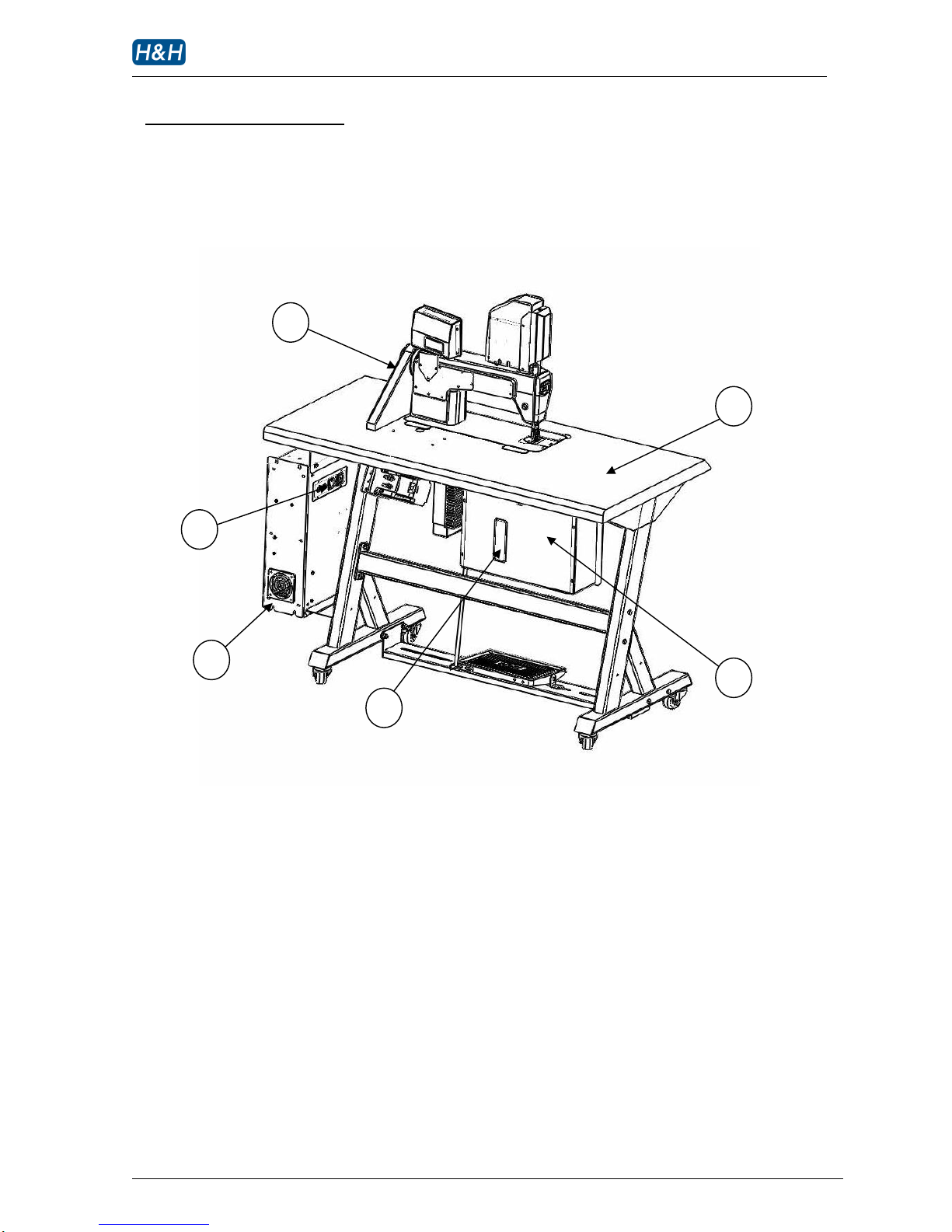
> Identification of Components
>> Front View
1. touch screen panel
2. welding head assembly
3. ultrasonic stack cover
4. foot pedal
5. knee switch
6. transporting castor
7. ultrasonic power supply
8. electronic actuator
9. sewing machine feed pitch adjusting knob
4
6
1
7
3
5
8
2
9
US-501 operation manual
US-501 R02 13.07.09 Display version 4, PLC version 4 P. 11 of 31
> Identification of Components (cont.)
>> Rear View
1. belt shroud
2. ultrasonic power supply access panel
3. cooling fan inlet
4. circuit breaker reset access hole
5. main electrical box
6. table top
1
3
2
4
5
6

US-501 operation manual
US-501 R02 13.07.09 Display version 4, PLC version 4 P. 12 of 31
> Identification of Components (cont.)
>> Power ON/OFF switch
1. power ON button
2. power OFF button
>> Welding Head Assembly
1. press foot
2. feed dog
3. bottom utility plate
4. ultrasonic horn
5. cutter bit
6. cutter mount
1
2
1
2
3
4
5
6

US-501 operation manual
US-501 R02 13.07.09 Display version 4, PLC version 4 P. 13 of 31
> Principle of Ultrasonic Welding
Ultrasonic energy is a form of physical vibration. The commonly used vibration frequencies are 20
kHz, 30 kHz, 35 kHz and 40 kHz. Different materials exhibit different behaviors under ultrasonic
vibration. Synthetic material generates internal heat under ultrasonic vibration. The US-501
machine generates vibration on the surface of the horn. Fabric with at least 50% synthetic material
is placed on the surface of the horn. A special tool called cutter bit is press against the horn so that
fabric between the horn and the cutter bit is exposed to vibration. The heat generated in the fabric
portion under pressure is heated up instantly and the temperature is high enough to melt the fabric,
hence resulting in an ultrasonic cut.
US-501 is engineered to careful manage this vibrating energy in order to slice fabric consistently in
single layer or multi-layer application.
During single layer operation, fabric is melted and separated resulting in a fray free edge. While
during multi-layer operation, layers of fabrics are cut but at the same time the edges of the fabric
are melted and fused together resulting in a ‘weld’. This process is sometimes referred as a ‘cut and
seal’or ‘line bonding’operation.

US-501 operation manual
US-501 R02 13.07.09 Display version 4, PLC version 4 P. 14 of 31
> Preparation for Installation
Installation must be carried out by authorized personnel. Follow the steps below:
1. Position the machine on a flat surface and allow at least 50cm clearance on both sides as well as
the back side, this is essential to allow enough room for carrying out necessary service and
maintenance
2. Cut loose all packing cable ties and materials in order to free up all machine movements.
3. Connect the power plug to a suitable outlet with at least 15A capacity.
4. Make sure there is enough lubricate oil in the sewing machine. Oil may be drained at the time of
shipping.
5. Prepare some fabric for testing
6. The machine is now ready for operation.

US-501 operation manual
US-501 R02 13.07.09 Display version 4, PLC version 4 P. 15 of 31
> Control Method
>> Touch Screen Control Panel
Almost all setting and timing control of the machines can be input from the touch screen control
panel. Use you fingertip to touch the parameter to be modified. Switch to different pages to
modify other parameters (refer to section on control menu navigation). The screen has a
protective cover to prevent the surface from damage and scratch, however, avoid using
excessive force when touching the panel. You can also change the contrast of the display so as to
obtain the best picture when viewing at a different angle.
>> Foot Switch
The foot pedal is to control the speed of the sewing machine head. Use it as the same way as an
ordinary sewing machine.
To start cutter - press forward.
To change the speed of cutting –ease back slightly from the forward position. The speed of
cutting is proportional to the pedal position in the forward
direction.
>> Knee Switch
The knee switch is to lift the press foot and stamp. When press foot is needed to be raised, apply
pressure to the knee switch. The pressure foot is lifted mechanically while the stamp is lifted up
electronically. Release the knee switch to lower the press foot and the stamp.

US-501 operation manual
US-501 R02 13.07.09 Display version 4, PLC version 4 P. 16 of 31
> Control Method (cont.)
>> Control Menu Navigation
The US-501 has a number of parameters that can be adjusted according to the operational
situations. These parameters are arranged in different menu pages on the touch screen control
panel according to their functionality. The structure of the menu page arrangement is
represented in the following diagram.
US-501 Menu Structure
H&H
main
cutter calibration
monitor
alarm
program version
pattern

US-501 operation manual
US-501 R02 13.07.09 Display version 4, PLC version 4 P. 17 of 31
> Start Up and Shut Down Procedures
Please take steps to follow the procedures described below:
Location of power ON/OFF switch
1power ON button
2power OFF button
>> Start up Procedures
Turn on the machine by pressing the green power ON button
The 1st page is welcome note will show once the machine is powered on.
2
1

US-501 operation manual
US-501 R02 13.07.09 Display version 4, PLC version 4 P. 18 of 31
> Start Up and Shut Down Procedures (cont.)
>> Start up Procedures (cont.)
The 2nd page is program loading page, it will process for several seconds and carry to the main
page.
Briefly after the power is turned on, the electronic positioning system will direct the stamp to
predefined position called home position. The stamp will use this position as a reference for all
future movement. At the home position, the positioning system has a coordinate equal to ‘0’.
During the homing process, do not interfere with the motion of the stamp as the machine may
pick up incorrect data resulting in incorrect position in the subsequence operation.
>> Shut down Procedures
WARNING !
Please follow the shut down procedures strictly to avoid damage to the ultrasonic
system.
1Always allow at least 5 seconds idle before turning off the power.
2Always allow at least 5 seconds after the shut down before turning on the machine again.
3Turn off the machine by pressing the red power OFF button

US-501 operation manual
US-501 R02 13.07.09 Display version 4, PLC version 4 P. 19 of 31
> Basic Operation
>> Control Panel Main page
Going into the operation main page. Basic parameters are needed to be set before operating the
machine. Refer to the corresponding sections for detail explanation.
1cutter assembly
2cutter pressure regulator (the number is the real time pressure, selecting range is -10 to +5)
3sonic on/off switch, ready is sonic power on while off is sonic power off
4cloth thickness selector (the number is the real time relevant speed, selecting range is 0 to 4) R1
5sonic on/off switch, ready is sonic power on while off is sonic power off
6sonic frequency
7sonic power regulator (the number is the real time power, selecting range is 1 to 10)
8sonic cooling fan speed
9cutter operation mode indicator (continuous working mode or pattern on processing mode)
10 to next page
11 sonic power consumption indicator
R1: Thicker cloth will be more difficult to cut, a slower speed will be more appropriate; conversely,
thinner cloth will be easier to cut, can apply with a faster speed
1
8
7
2
9
2
4
2
5
2
2
2
6
2
3
2
1
1
0
2
1
0
Table of contents
Other H&H Welding System manuals


Popular Welding System manuals by other brands


Lincoln Electric
Lincoln Electric IDEALARC CV-305 Operator's manual

HTP
HTP Invertig 301 manual

Car-O-Liner
Car-O-Liner CM Series instruction manual

Taurus
Taurus MIG 280 PLUS Operation manual

Lincoln Electric
Lincoln Electric PRO-MIG 175 IM810 Operator's manual

Weldcote
Weldcote TIG STRIKER 200 AC Quick guide manual