omisa 6160/LI User guide

USE AND MAINTENANCE
INSTRUCTION MANUAL
Butt welding machine to weld pipes and fittings in
thermoplastic material suitable for sewer pipelines
/LI
6160/LI
Version1/2016
O.M.I.S.A. S.r.l.
Via Verga 9/11 -20845 - Sovico (MB) - ITALY
Tel. +39 039 2323028 | Fax +39 039 2018579

Dear costumer,
Thanks for having chosen an OMISA product! This instruction manual has been
prepared in order to fully appreciate the superior quality of our product. Inside you will
find all the necessary information and warnings for a safe and proper use. We want to
advise you to read it before proceeding with the operations. We are sure that it will be
easier for you to become familiar with the new device and to use it for a long time with
great satisfaction.
Cordially,
O.M.I.S.A. S.r.l

O.M.I.S.A. Srl –6160/LI - Use and Maintenance Instruction Manual - Version 1/2016
3/22
INDEX
Page
1. GENERAL DESCRIPTION OF THE MACHINE 4
2. TRANSPORT MODE 6
3. TECHNICAL FEATURES 6
4. SAFETY INSTRUCTIONS 7
4.1 WORK STATION –ENVIRONMENT CONDITION 7
5. CARE AND MAINTENANCE 8
6. PROPER USAGE 8
7. INCONVENIENCES AND SOLUTIONS 8
8. DISPOSAL 8
9. WELDING SETTING 9
10. WELDING OPERATION 10
TECHNICAL DRAWING AND LIST OF SPARE PARTS 11
CONFORMITY DECLARATION 20
WARRANTY CONDITION 21
Text, diagrams and data are corrected at time of going to print. In the interest of continuous improvement of our products,
technical specifications are subject to alteration without prior notice.

O.M.I.S.A. Srl –6160/LI - Use and Maintenance Instruction Manual - Version 1/2016
4/22
1. GENERAL DESCRIPTION OF THE MACHINE
The welding machine 6160/LI. was designed and manufactured for welding of pipes and/or fittings in
thermoplastic material for sewer pipelines and for stated diameters.
This welding machine is mainly composed by:
•Basic machine with electric planing tool and thermoelement support.
•Pair of main clamps for pipes fastening and relevant reductions.
•Work bench frame/ protection for transport; tool box for thermoelement and reductions.
Basic machine with electric planing tool and support for thermoelement:
The basic machine is composed by two carriages in aluminum casting, one fixed and one sliding
provided with a spring device, which allows to determinate the pressure during various welding steps
and which is useful for the movement of the carriage itself.
This device is driven by a hand wheel (A) connected to a pinion-rack system, which maintains a
constant pressure (indicated by the reference C) when it is locked by the lever (B).
The movable carriage is equipped by 4 sliding sheets with a low coefficient of friction and high
abrasion resistance which are suitable for using in fields.
Carriage slides on two shafts, chromed and adjusted, anchored to two shoulders which can be fixed
to the work bench frame.
On the back side of the machine, the extractable thermoelement support and planing tool slide on a
chromed and adjusted shaft; the linear sliding and the turnover are assured by blow-by ball bearings.
The thermoelement support, manufactured in aluminum casting, allows the right positioning of the
thermoplate (already supplied), during the heating stage and its housing, when not used, helping the
operator during the following welding stages.
The electric planing tool, manufactured in aluminum casting too, allows a quick flat parallel on both
pipes and/or fittings end to be welded. Blades are mounted at 180° the one to each other and they
are sharpened on both sides. It will be only needed to turn them in order to use the second
sharpening. In any case, do not sharpen blades by yourselves, this will cause a bad electric planing
tool working.
The electric planing tool is equipped by a mechanical device (A) which allows the removal of jaws in
case they are turned to 7,5°, in order to obtain the right alignment of the elements which have to be
welded. The planing tool is provided with a safety micro-switch (B) which avoid the starting of the
planing tool itself if it is not positioned on the workplace, although accidental actuation of the switch
positioned on the handle (C). The planing tool has also a mechanical hanger for safety (D).
Picture 1

O.M.I.S.A. Srl –6160/LI - Use and Maintenance Instruction Manual - Version 1/2016
5/22
Before feeding the electric planing tool, make sure that the used electrical panel comply with the
technical features of the electric planing tool and above all that is equipped of grounded wire.
Pair of main clamps for pipes fastening and relevant reductions:
The pair of main clamps, made in steel, allows a safety locking of pipes and/or fittings to be welded.
They have been made in order to house different reductions to clamp pipes and fittings from Ø40 to
Ø160mm. The upper reductions are shaped to make also branches and tees at 45° and 60°.
Clamps are 7,5° rotable and it IS enough, without removing the screws (A), to unscrew the clamp
group up to the end of the buttonhole positioned on the clamp support (B).
Do the same operation on the other jaw turning it on the opposite side. I will get a 15° segment.
Picture 2 Picture 3
Work bench frame/ protection for transport; tool box for thermoelement and reductions:
The work bench frame /transport protection is made of steel to assure stability to the whole machine
during welding process and when the job is finished, it is able to grant a good protection during
transport.
On the frame is possible to position the tool box for thermoelement, reductions and equipped pipe
supports (from Ø40 to Ø160; Ø56 and Ø140 optional)
All parts of the machine 6160/LIare made in order to withstand to atmospheric agentattack.

O.M.I.S.A. Srl –6160/LI - Use and Maintenance Instruction Manual - Version 1/2016
6/22
2. TRANSPORT MODE
The machine is supplied inside its transport box protected by proper packing. It is already assembled
and able to work.
After receiving it, unpack the machine and inform the transport company about further occurred
damages.
3. TECHNICAL FEATURES
6160/LI
Welding capacity
Ø40 Ø160 mm
Pipe and fitting material
PEand other thermoplastic materials
Dimensions/weight basic machine
660x520x 470 mm - 32 Kg
Carriage stroke
190mm
Power of planing tool
0,71Kw
Voltage of planing tool
230V- 50/60Hz
Transmission of planing tool
Belt
Dimensions / weight support frame
635x583x846 mm -6 Kg
Dimensions / weight reductions box
430x320x100 mm - 3,5 Kg

O.M.I.S.A. Srl –6160/LI - Use and Maintenance Instruction Manual - Version 1/2016
7/22
4.SAFETY INSTRUCTIONS
DANGER! Read all these instructions before using the device. Follow carefully the
indications in order to avoid personal injuries, damages to the machine and mistakes
during welding operation. The equipment should be used by qualified personnel and
should not remain unguarded.
O.M.I.S.A. Srl cannot anticipate every possible situation that might involve a potential hazard.
Warnings in this manual and in the machine are therefore not all inclusive.
4.1 WORK STATION –ENVIRONMENTAL CONDITION
The use of any mechanical and electrical device, require the observance of some basic rules:
-Keep clean the work station and the equipment.
-Do not use the machine with inflammable liquids or gases, chemical or corrosive agents
nearby.
-Always take care during the use of the machine.
-The machine must be used by qualified personnel and should be not left unattended.
-Take care of feeding cables of the thermoplate and electric planing tool, do not knot or crush
them and do not twist them around equipment.
-Avoid use of extension as much as possible.
-Make sure that the used electric panel comply with the electrical features of the thermoplate
and electric planing tool that it is equipped of grounded wire
-Never grasp the electric planing tool blades and neither sharpen them; this operation will
cause a bad electric planning tool working because the blades would go inevitably undersize.
-Always wear proper clothes: long trousers, long sleeved racket, anti-warm and anti-cuts
safety gloves for maintenance operation and safety shoes, helmet if used in building places.
-Do not wear scarf, necklace, rings or any other object that could get entangled.
-Do not leave the machine exposed to atmospheric agents. Do not use the machine with
unfavorable condition (snow, fog, rain, high wetness rate, etc.)
-Respect safety working regulations in force in every country you are going to use the
machine
This welding machine was designed and manufactured complying with the European Standard in
force.
The use of a 6160/Li machine requires the observance of some specific rules:
During operations stay a safe distance away from the machine.
Do not stand or reach in the machine. Keep other people away from the work area.
During operations pay attention handling to the thermoelement, it can reach 300°C! We
highly recommend storing it in the designed steel box immediately after use.
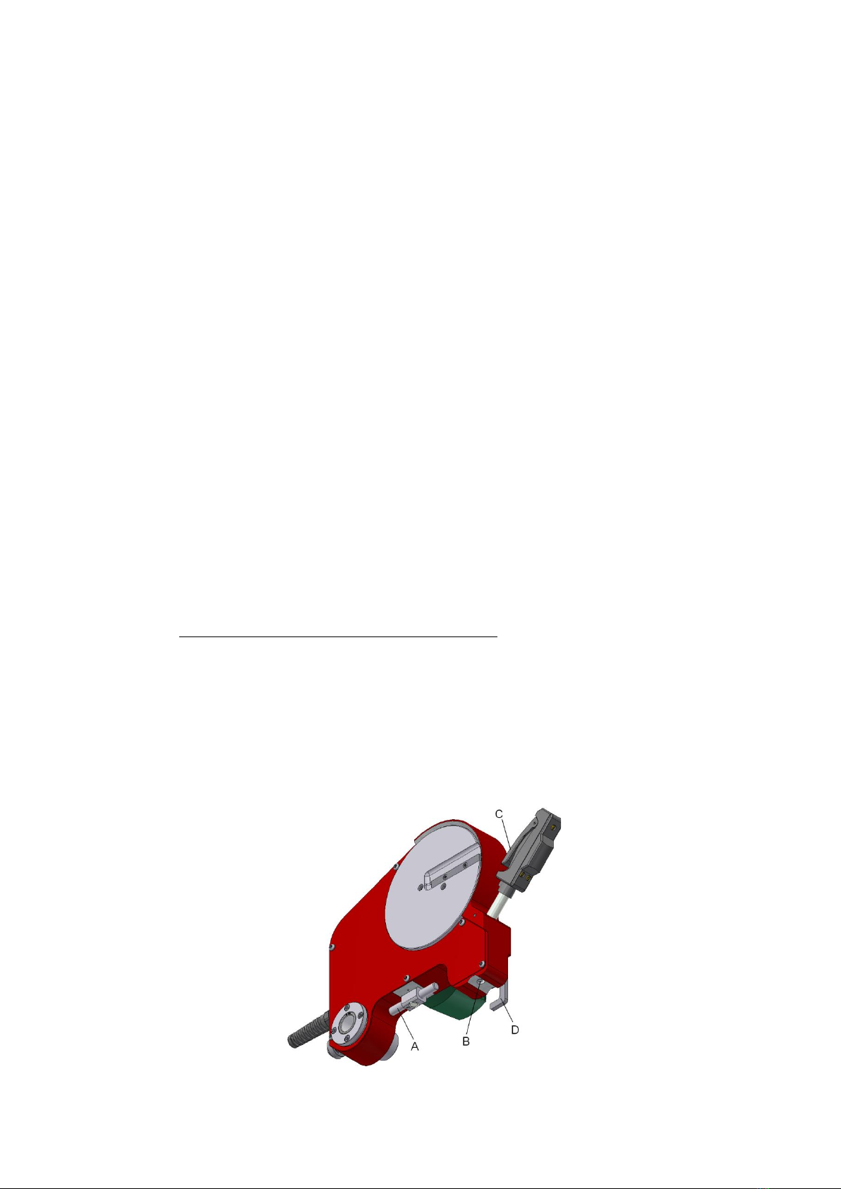
During operations pay attention handling to the planing tool, it is very sharp!
We highly recommend storing it in the designed steel box immediately after use.
Never touch and sharpen the blades of the planing tool, this operation would cause a bad
working of the electric planing tool as the blades would go inevitably undersize.
This welding machine has been designed and manufactured according to the European regulation in
force and to the specific rules relevant to the butt welding machines for making butt welding joint of
pipes and/or fittings in polyethylene (PE) for combustible gas, water and other pressure fluids
transportation.

O.M.I.S.A. Srl –6160/LI - Use and Maintenance Instruction Manual - Version 1/2016
8/22
5. CARE AND MAINTENANCE
To ensure that machine works properly observe the following maintenance recommendations:
-Completely clean the machine at the end of any job, especially if the dwell is long.
-Check that the sliding shafts are always clean and lubricated.
-Check the functionality of the electric planing tool and when used, verify the blade sharpening.
Remember that blades are sharpen on both side, so it will be only needed to turn them in
order to use the second sharpening.
-Check the tension of transmission belt of the electric planing tool.
-Check the functionality of clamp lock system.
In order to make the maintenance operation is required:
→Properly insulation of the electrical plant of the machine; UNPLUG THE FEEDING CABLE FROM
THE ELECTRICAL SUPPLY.
→Do not remove protection of mobile parts (e.g. planing tool shaped sheet), if not required
maintenance on them. Place them back as soon as all operation are finished.
6. PROPER USAGE
The machine was designed for welding pipes and/or fittings in thermoplastic material, so it
should be NOT used for jointing other materials.
7. INCONVENIENCES AND SOLUTIONS
INCONVENIENCE
SOLUTIONS
The electric planing tool does not work.
Check that:
The electric plant is connected and comply with
the technical features of the electric planing
tool. Switches at the beginning of the plug and
on the machine are closed.
The electric planing tool does not face.
Check that:
The blade sharpening placed on two turning
plates is in good condition.
The cutter block plate of the electric planing
tool does not turn, even if the motor works.
Check that:
The transmission belt is in tension.
(Disassemble the protection shaped sheet and
eventually operate on the cam, turning it. Then
assemble again the shaped sheet).
8. DISPOSAL
Components of the machine are made by normal metal material so are recyclable. They have to be
put to recycling. For the non-recyclable components (as electronic ones) you should contact the local
waste disposal authority.
Components that comes with the picture show here, that means waste of electric and
electronic equipment, have to be absolutely disposed separately from domestic waste and
by authorized and certified companies.

O.M.I.S.A. Srl –6160/LI - Use and Maintenance Instruction Manual - Version 1/2016
9/22
9.PREPARATION TO THE WELDING
This welding machine is manufactured only for welding pipes and/or fittings in thermoplastic
materials for sewage pipelines; any other use is to be considered not proper and dangerous and it
will relieve the manufacturing company from any kind of responsibility.
Before using the machine, carefully check the perfect working and efficiency of the safety devices
and movable parts, that are not broken or locked and that all parts are mounted in the right way.
Verify that all other conditions, which could influence the regular working of the machine, are
optimal.
Be sure that outlet and plug of the planing tool are compatible. Do not use extensions and adapters
as much as possible, but if they are needed, use only the ones complied with safety rules in force,
checking that cables section is suitable to absorbed power by the planing tool.
The electric planing tool is supplied with grounded wire, so the electrical safety is assured only if it is
correctly connected to an effective grounded network as foreseen by the law in force about electrical
safety.
Unwind for its whole length the electrical feeding cable of the planing tool and do not leave it
inserted into the network, when the planing tool is not used. If required bydiameters of pipes and/or
fittings to be welded, insert relevant reductions into the main clamps, in the proper housing. Make
sure that they are fixed with the proper housing placed on the horizontal flat of the two carriages
and make sure that the two clamps are aligned.
At the same time switch on the thermoplate, not before having completely read the use and
maintenance instruction manual of this article.

O.M.I.S.A. Srl –6160/LI - Use and Maintenance Instruction Manual - Version 1/2016
10/22
10. WELDING OPERATION
Insert the pipe and/or fittings to be welded and make sure that they are properly clamped into the
jaws.
Leave enough space to put the electric planing tool and thermoplate between then. The locking
efficacy is regulated by the adjustment of the brass pawl which is positioned on the clamp’s upper
part.
Remember that clamps on the fixed carriages can be perpendicularly translated to the sliding axis of
the mobile carriage of some millimeters. Then it should be properly locked again. In this way it can be
avoid further alignment “mistakes” between the parts to be welded.
Before starting with the real welding stage, face pipes and/or fittings.
Place the electric planing tool between the two parts which have to be joined, using EXCLUSIVELY its
handle (picture 1, part C) and never through the turning plates. The handle, in fact, is equipped with
a safety switch which prevent any accidental starting of the electrical motor. Then, lock the planing
tool using the security hanger (picture 1, part D).
Always be careful during the facing stage, as it is very important in order to get a good final welding.
During this stage, due to safety reasons, it is needed to keep a hand on the movement hand-wheel
of the mobile carriage, and the other one on the control handle of the planing tool (picture 1, part
C) after locking the lever and established a light planing pressure of about 80N.
The facing process is finished and correct only when the result of the operation is a continuous chip
with the same thickness of the pipe and/or fitting on both elements to weld.
At this point, bring the electric planing tool back to its initial position and place the thermoplate
between the two parts to weld.
The heating stage starts when the two parts get in touch with the thermoelement surface. This stage
ends when the bead and the foreseen time are reached.
Then, bring the thermoelement back to its position as fast as possible and join the two heated
surfaces.
Operating on the movement hand-wheel, get the heated end parts in touch to each other.
Reach the required pressure and lock the spring-loaded rack-pinion device acting on the lever
Keep the two pipe ends in touch for the required time in order to allow a complete and gradual
cooling to obtain a correct welding.
It is very important, at this stage, that the welded parts do not suffer any kind of mechanical stress.

O.M.I.S.A. Srl –6160/LI - Use and Maintenance Instruction Manual - Version 1/2016
11/22
TECHNICAL DRAWINGS
AND LIST
OF SPARE PARTS

O.M.I.S.A. Srl –6160/LI - Use and Maintenance Instruction Manual - Version 1/2016
12/22

O.M.I.S.A. Srl –6160/LI - Use and Maintenance Instruction Manual - Version 1/2016
13/22
DRAWING 1
Pos.
Description
Art. Code
Qnt
Pos.
Description
Art. Code
Qnt
1
Left support
160LI.0A.0004
1
32
UNI 5931 M6x25 screw
V.5931.6x25
1
2
Sliding shaft
160LI.0A.0001
3
33
UNI 6592 M6 washer
V.6592.6
1
3
Thermoplate support
160LI.0B
1
34
Block rack
HWT.0A.0014
1
4
Electric planning tool
160LI.0D
1
35
UNI 6592 M10 washer
RON.6592.10
1
5
Jaws left complete
GAN.HWT.SX
1
36
UNI 5931 M6x25 screw
V.5931.6x25
1
6
Jaws right complete
GAN.HWT.DX
1
37
UNI 5923 M6x10 screw
V.5923.6x10
4
7
UNI 5931 M10x25 screw
V.5931.10x25
2
38
UNI 7435 Ø10 seeger
S.7435.10
1
8
UNI 6592 M10 washer
RON.6592.10
2
39
Pinion M1.5 Z15
160LI.0A.0008
1
9
Support jaws
HWT.0A.0006
2
40
Pinion shaft lock
HWT.0A.0013
1
10
UNI 5931 M10x30 screw
V.5931.10x30
2
41
Lever
HWT.0A.0023
1
11
Base for pipe support
160LI.0A.0016
2
42
UNI 7435 Ø12 seeger
S.7435.12
2
12
UNI 5931 M6x20 screw
V.5931.6x20
2
43
Movement hand wheel
160LI.0A.0011
1
13
Pin block support rotating
HWT.0A.0018
2
44
Rod movement hand wheel
160LI.0A.0053
3
14
Support rotating
HWT.0A.0017
2
45
Knob
GAN.110PB.0004
3
15
Pipe support Ø160
2
46
UNI 5927 M8x8 screw
V.5927.8x8
1
16
UNI 5931 M6x12 screw
V.5931.6x12
2
47
UNI 5923 M6x6 screw
V.5923.6x6
3
17
UNI 5931 M10x20 screw
V.5931.10x20
4
48
Pinion shaft
160LI.0A.0010
1
18
UNI 6592 M10 washer
RON.6592.10
4
49
UNI 6604 4x4x25 tang
L.6604.4x4x25
1
19
UNI 5933 M8x16 screw
V.5933.8x16
1
20
Moving base
160LI.0A.0003
1
21
Right support
160LI.0A.0005
1
22
UNI 5937 M10x20 screw
V.5737.10x20
8
15
Pipe support Ø40
HWT.0A.0042
2
23
UNI 6592 M10 washer
RON.6592.10
8
15
Pipe support Ø50
HWT.0A.0043
2
24
Stop rod rack
160LI.0A.0026
1
15
Pipe support Ø56 (optional)
HWT.0A.0044
2
25
UNI 5931 M6x16 screw
V.5931.6x16
1
15
Pipe support Ø63
HWT.0A.0045
2
26
Pressure indicator
HWT.0A.0015
1
15
Pipe support Ø75
HWT.0A.0046
2
27
Spring
160S.0A.0016
1
15
Pipe support Ø90
HWT.0A.0047
2
28
Stop for spring
HWT.0A.0025
1
15
Pipe support Ø110
HWT.0A.0048
2
29
Rack M1.5
160LI.0A.0019
1
15
Pipe support Ø125
HWT.0A.0049
2
30
Shaft support bearing
160LI.0A.0007
1
15
Pipe support Ø140 (optional)
HWT.0A.0050
2
31
Fixed base
160LI.0A.0002
1
15
Pipe support Ø160
HWT.0A.0051
2

O.M.I.S.A. Srl –6160/LI - Use and Maintenance Instruction Manual - Version 1/2016
14/22

O.M.I.S.A. Srl –6160/LI - Use and Maintenance Instruction Manual - Version 1/2016
15/22
DRAWNIG 2
Pos.
Description
Art. Code
Qnt
Pos.
Description
Art. Code
Qnt
1
Knob
160S.0B.0003
1
2
Lever
160LI.0B.0003
1
3
Thermoplate support body
160LI.0B.0001
1
4
Support for polywelder
100N.0A.0054
1
5
UNI 5739 M10x20 screw
V.5739.10x20
1
6
Bearing
CUSC.6200.2Z
1
7
UNI 6592 M10 washer
RON.6592.10
1
8
UNI 5927 M6x6 screw
V.5927.6x6
2
9
Polywelder block knob
125PB.0A.0027
1
10
UNI 5931 M6x16 screw
V.5931.6x12
4
11
Bearing seat
HWT.0D.0002
1
12
2540 blow-by balls coupling
HWT.0B.0004
2
13
UNI 5927 M6x6 screw
V.5927.6x6
1
14
Knob
GAN.160.0008
1
15
Stop for polywelder
160LI.0B.0005
1
16
Lock
160LI.0B.0004
1
17
Washer
315P.0D.0047
1
18
UNI 5933 M6x16 screw
V.5933.6x16
1

O.M.I.S.A. Srl –6160/LI - Use and Maintenance Instruction Manual - Version 1/2016
16/22

O.M.I.S.A. Srl –6160/LI - Use and Maintenance Instruction Manual - Version 1/2016
17/22
DRAWNING 3
Pos.
Description
Art. Code
Qnt
Pos.
Description
Art. Code
Qnt
1
ISO 7380 M6x10 screw
V.7380.6x10
6
33
Pipe handle
160LI.0D.0016
1
2
Shaped sheet
160LI.0D.0008
1
34
UNI 5927 M6x14 screw
V.5927.6x14
1
3
UNI 5931 M6x30 screw
V.5931.6x30
2
35
Handle
160LI.0D.0060
1
4
Support blade plate with slot for belt
HWT.0D.0007
1
36
Micro switch
160LI.0D.0017
1
5
Z26 trapezoidal belt
CIN.TRAP.Z26
1
37
UNI 6592 M4 washer
RON.6592.4
2
6
UNI 5931 M6x20 screw
V.5931.6x20
4
38
UNI 5931 M4x30 screw
V.5931.4x30
2
7
Bearing seat
HWT.0D.0002
1
8
2540 blow-by balls coupling
HWT.0B.0004
2
9
UNI 5923 M8x12 screw
V.5923.8x12
1
10
M16x1.5 gland cable
PRC.S.16N
1
11
UNI 5739 M10x20 screw
V.5739.10x20
1
12
Bearing
CUSC.6200.2Z
1
13
UNI 6592 M10 washer
RON.6592.10
2
14
M12x1.5 press cable
PRC.12N
1
15
Bearing 16013
CUSC.16013
1
16
Support blade plate
HWT.0D.0008
1
17
Blade
HWT.0D.0009
2
18
ISO 7380 M4x6 screw
V.7380.4x6
4
19
Pulley belt
HWT.0D.0003X
1
20
UNI 5923 M8x12 screw
V.5923.8x12
2
21
Eccentric
250P.0D.0010X
1
22
Drill
160S.0D.0059
1
23
Safety pivot for hook
160LI.0D.0015
1
24
Safety hook
HWT.0D.0011
1
25
Lock pivot milled
HWT.0D.0005
1
26
Block milled
HWT.0D.0004
1
27
Damper for ball
HWT.0D.1004
1
28
Ball Ø4,75mm
SF.4,75
1
29
Electric planning tool body
160LI.0D.0001
1
30
Ball Ø4,75mm
SF.4,75
1
31
Damper for ball
HWT.0D.1004
1
32
UNI 5923 M6x5 screw
V.5923.6x5
1

O.M.I.S.A. Srl –6160/LI - Use and Maintenance Instruction Manual - Version 1/2016
18/22

O.M.I.S.A. Srl –6160/LI - Use and Maintenance Instruction Manual - Version 1/2016
19/22
DRAWING 4 (GAN.160LI.DX; GAN.160LI.SX)
Pos.
Description
Art. Code
Qnt
Pos.
Description
Art. Code
Qnt
JAWS RIGHT COMPLETE
GAN.160LI.DX
1
JAWS LEFT COMPLETE
GAN.160LI.SX
1
1
Complete reducing ring
1
Complete reducing ring
2
Hinge
GAN.160.0004
2
2
Hinge
GAN.160.0004
2
3
Rivet
GAN.160.0005
3
3
Rivet
GAN.160.0005
3
4
Locking lever
GAN.160.0006
1
4
Locking lever
GAN.160.0006
1
5
Black hand grip
GAN.160.0007
1
5
Black hand grip
GAN.160.0007
1
6
Adjustment revolving plug
GAN.160.0009
1
6
Adjustment revolving plug
GAN.160.0009
1
7
Seeger DIN 471 Ø8
S.471.8
1
7
Seeger DIN 471 Ø8
S.471.8
1
8
UNI 5923 M6X50 dowel
V.5923.6x50
1
8
UNI 5923 M6X50 dowel
V.5923.6x50
1
9
Right upper half jaw
GAN.160DX.0002
1
9
Left upper half jaw
GAN.160SX.0002
1
10
Revolving plug for half ring locking
GAN.160.0008
4
10
Revolving plug for half ring locking
GAN.160.0008
4
11
Right lower half jaw
GAN.HWTDX.0001
1
11
Left lower half jaw
GAN.HWTSX.0001
1
12
Screw rivet
GAN.160.0003
1
12
Screw rivet
GAN.160.0003
1
1
Ø40 complete reducing ring
Ri.160.40
1
1
Ø40 complete reducing ring
Ri.160.40
1
1
Ø50 complete reducing ring
Ri.160.50
1
1
Ø50 complete reducing ring
Ri.160.50
1
1
Ø56 complete reducing ring (optional)
Ri.160.56
1
1
Ø56 complete reducing ring (optional)
Ri.160.56
1
1
Ø63 complete reducing ring
Ri.160.63
1
1
Ø63 complete reducing ring
Ri.160.63
1
1
Ø75 complete reducing ring
Ri.160.75
1
1
Ø75 complete reducing ring
Ri.160.75
1
1
Ø90 complete reducing ring
Ri.160.90
1
1
Ø90 complete reducing ring
Ri.160.90
1
1
Ø110 complete reducing ring
Ri.160.110
1
1
Ø110 complete reducing ring
Ri.160.110
1
1
Ø125 complete reducing ring
Ri.160.125
1
1
Ø125 complete reducing ring
Ri.160.125
1
1
Ø140 complete reducing ring (optional)
Ri.160.140
1
1
Ø140 complete reducing ring (optional)
Ri.160.140
1
1
Ø160 complete reducing ring
Ri.160.160
1
1
Ø160 complete reducing ring
Ri.160.160
1

O.M.I.S.A. Srl –6160/LI - Use and Maintenance Instruction Manual - Version 1/2016
20/22
CONFORMITY DECLARATION
O.M.I.S.A. S.r.l.
Via Verga 9/11 -20845 - Sovico (MB) - ITALY
Tel. +39 039 2323028 | Fax +39 039 2018579
DECLARES
That the welding machine:
Manufactured and sold by our company in compliance with:
EN 60335-1, EN60335-2-45
EN 60204-1 (CEI 44-5), EN 60204-1 (CEI 44-6)
2004/108/CE, 2006/95/CE
EN 55014, EN 61000-3-2, EN 61000-3-3
2006/42/CE
2002/95/CE, 2002/96/CE, 2003/108/CE
This declaration loses its validity in case of changes to the welding machine without our
written authorization.
Sovico, 10th September 2019
O.M.I.S.A. S.r.l.
Table of contents
Other omisa Welding System manuals
Popular Welding System manuals by other brands

Miller
Miller Intellifire 204 owner's manual

Lincoln Electric
Lincoln Electric Power MIG 350MP Technical specifications

Castolin Eutectic
Castolin Eutectic POWERmax2 Operating manual and Spare parts list

Chicago Electric
Chicago Electric 46092 56358 Owner's manual & safety instructions

HBS
HBS IT 2002 operating manual

Defort
Defort DWI-160 user manual