H&K PRET 601774 User manual

User Manual
Soup cooker 601774
H&K EUROPE

Contents
Warning 3
Introduction 4
Manufacturer’s details 4
Warranty 5
Purchase record 5
Installation 6
Operation 6
Cleaning 8
Trouble shooting 8
Controller configuration 9
Setting the operational temperature 10
Controller error codes 10
Replacement parts 10
Wiring schematic 11
Issue 1:2 06.05.03 2

Warning
Do not operate, maintain or repair the soup cooker without first reading
this manual
Take care when moving the unit as it is of considerable weight
Alteration of the controller may result in operating difficulties
Disconnect power source before maintaining or repairing the unit
Do not immerse the unit into water
Allow the cooker to cool down prior to emptying or cleaning
Repairs should be undertaken by a qualified engineer
Only genuine H&K Ltd replacement parts should be used
Issue 1:2 06.05.03 3

Introduction
The soup cooker has been designed to cook the soup within in its packaging
and then to be held at the point of service. The soup cooker has independent
digital read-out controls for each well. This allows 6 litres of soup to be cooked
in each well giving a total of capacity 12 litres.
Manufacturer’s details
H&K Equipment Ltd
1 Cosford Lane
Swift Valley
Rugby
CV21 1QN
United Kingdom
Tel: +44 (0) 1788 554000
Fax: +44 (0) 1788 554100
H&K Manufacturing Ltd
Cherry Orchard Industrial Estate
Balleyfermont Road
Dublin 10
Republic of Ireland
Tel: +353 (1) 6055400
Fax: +353 (1) 6055466
You can also find us on the web at www.hki.com
“CE” mark indicates that the product compiles with the European requirements
for safety, health, environment and the customer
Issue 1:2 06.05.03 4

Warranty
Equipment manufactured by H&K Ltd is guaranteed for a period of one year
from date of purchase. H&K Ltd warranty terms cover labour charges and
replacement of defective parts within this period. Claims for defective
equipment will be accepted if the defect is a result of manufacturing error or of
a part’s non-compliance. H&K Ltd does not accept responsibility for defects
caused by the mishandling, abuse or neglect of equipment. Parts replaced
after the one-year period has elapsed are covered under warranty for 90 days.
Purchase record
This information should be entered upon receipt of the cooker
Cooker 1
Date installed……………………………………
H&K Ltd quality number………………………..
H&K Ltd electrical number……………………..
These numbers can be found on the rear of the unit.
Please quote them in any relevant correspondence.
Issue 1:2 06.05.03 5

Installation
Upon receipt of equipment inspect for damage. Any damaged parts should
be reported to H&K Ltd within 24 hours of receiving the unit.
Remove all paper from the equipment.
Wipe clean with a damp cloth using a mild soap and water mixture
Electrical supply:230V single phase, 50 Hz, single phase, 13Amp
Temperature settings on the controller have been factory pre-set and should
not require adjustment.
Operation
Once the unit has been positioned:
1. Ensure the water drain valves are in the off position.
2. Position product divider into the unit.
3. Fill each well water pan with warm water to the level required.
Water levels
1 bag of soup
2 bags of soup
3 bags of soup
Note: Only one well is required when cooking up to 6 litres of soup
Issue 1:2 06.05.03 6

4. Position soup bags into the unit.
5. Turn the on/off switch to the on position.
The cookers controller(s) will bring the operating temperature up to 93°C. This
will take approximately 15 minutes.
This temperature will then be held for 20 minutes to allow the soup to be
cooked. The red ‘heat’ neon indicates this operation.
The controller(s) will then adjust the temperature to 85°C so that the soup can
be held at the point of service. The red ‘hold’ neon will be illuminated.
CAUTION HOT!!!
6. The soup can now be transferred or held in the unit.
7. The unit must be turned off prior to reloading
Well two controlsWell one controls
Control fuse
Issue 1:2 06.05.03 7

Cleaning
Warning
Ensure the power is disconnected prior to any works commencing
Allow the water temperature to cool prior to emptying
The water can be drained from the unit by turning the drain valve handles to
the on position.
Once the water has drained from the unit, the drain valves should be closed to
the off position.
The exterior of the unit should be cleaned daily with damp cloth using a mild
soap and water mixture. Do not use abrasive cleaners, as they will damage
the finish of the stainless steel.
The interior of the unit should also be cleaned daily with a damp cloth using
a mild soap and water mixture.
Trouble shooting
Problem Cause Repair
Unit will not
work
1. Unit not plugged in
2. No power to unit
(Controller display not
illuminated)
3. Unit still not operating
1. Plug unit into relevant socket
2. Check power supply
(Mains plug fuse or control fuse
tripped, see *note)
WARNING! Electricity can kill
3 Contact service company
To remove
the control
fuse from
its holder
1. The fuse is located on the main control panel.
2. Ensure the power is disconnected
3. Using a flat head screwdriver, turn the holder anti-clockwise until the
fuse is released.
4. Check or replace fuse if required.
5. Re-position the fuse into the holder and screw clockwise until tight.
Issue 1:2 06.05.03 8

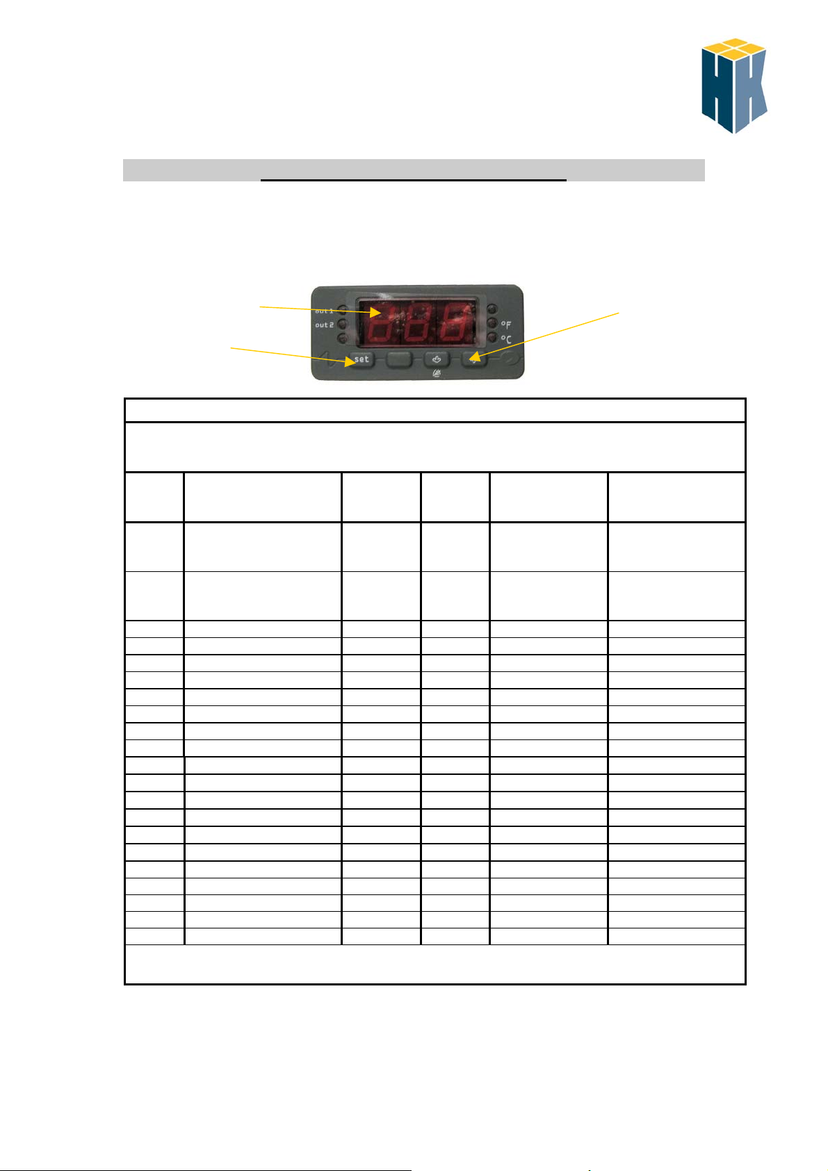
FK 401A Controller configuration
Read following instructions fully before commencing any alterations
This controller has been factory pre-set and should only be changed under instruction from H&K
Set key
Display Adjustment keys
Programming the controller to the cabinet
Commence with the unit switched on
If before all of the proceeding steps are completed no key action is detected for 60 seconds the
controller will revert back to its running mode.
Step Press Display
reads
Press Display reads Adjust display
(¿and Àkeys)
to read
1 ¿and À
simultaneously and
hold for approx. 4sec.
PA
Set
0
-19
2 ¿and À
simultaneously
hold
- / 0
Set
previous setting
2
3 ¿key / 0 Set previous setting 11
4 ¿key / 1 Set previous setting 2
5 ¿key / 2 Set previous setting 3
4 ¿key / 5 Set previous setting 1
5 ¿key / 6 Set previous setting -20
6 ¿key / 7 Set previous setting 80
7 ¿key / 8 Set previous setting 1
8 ¿key rA0 Set previous setting -2
9 ¿key rA1 Set previous setting 93
10 ¿key rA2 Set previous setting 93
11 ¿key rA3 Set previous setting 1
12 ¿key rA4 Set previous setting 0
13 ¿key rA5 Set previous setting 0
14 ¿key rb0 Set previous setting -2
15 ¿key rb1 Set previous setting 86
16 ¿key rb2 Set previous setting 86
17 ¿key rb3 Set previous setting 1
18 ¿key rb4 Set previous setting 0
19 ¿key rb5 Set previous setting 0
On completion of the proceeding steps press ¿and Àkeys simultaneously. The controller will adopt the new settings.
Issue 1:2 06.05.03 9

Setting the operating temperatures of the unit
Unit must be switched on
Press Set key once
Press set key twice
Adjust ¿and Àkey
Adjust ¿and Àkey
93
86
Controller error codes
Code Reasons Remedies
E2
Corrupted
memory
data
• There is a memory
corruption within the
configuration data of
the instrument
• Switch off the power.
• Reconnect the power supply - if code still
displayed replace the controller unit.
E0
Cabinet
probe
alarm
• Probe type incorrect
• Probe fault
• Fit correct probe type
• Check probe connections
E1
Evaporator
probe
alarm
• Probe type incorrect
• Probe fault
• The evaporator
temperature is
outside the limits of
the controller
• Fit correct probe type
• Check probe connections
• Test the temperature close to the probe to
ensure its between the set operating range
Replacement parts
Part Part number Quantity
Per unit
Lid handle BLO18707-2 2
Lid handle fixing screw BLO18707-3 2
On/off switch E01035 2
10 Amp fuse E01510 2
Fuse holder E01505 2
Controller E012342 2
Probe E01406 2
Transformer E04160 2
Mains plug E10040 1
Mains cable E06124 3M
Heater element E01235 2
Lamp neon E01008 4
Relay mini 30amp E04041 4
Timer E04045 2
Ball valve T60029 2
Issue 1:2 06.05.03 10

Wiring schematic
Issue 1:2 06.05.03 11
Table of contents