H&S CHS User manual

Read Safety Recommendations Before Operating Tool
Model
Number
Exhaust
Direction
Throttle
Type
Rated
Speed
Power
Output
Case
Material Weight Overall
Lenght
Body
Diameter
Working Air
Consumption Spindle Length & Thread
CHS Side Safety
Lever
6000
R.P.M.
2.0 H.P
1500 W Aluminum 8.0 Lb/
3.6 Kg
15 inch
381 mm
3.0 Inch
76.2 mm
40 cfm
(18.9 L/s) T2-5/8-11 x 1.1 inch (28mm)
Capacity
● 7 Inch (180 mm) or 9 Inch (230 mm) Type 27 Wheels
● 10 Inch Type 1 (Type 41) Cut-off Wheel
General Operation
Instructions, Parts and
Maintenance Manual
Model CHS
P.O. Box 393
Wadsworth, OH 44282 U.S.A.
Tel: +1 330 336 4550
Fax: +1 330 336 9159
www.hstool.com
Model CHS Hand Held Saw

This is meant to highlight sections of safety standards published by the American National Standards
Institute and the Occupational Safety and Health Administration. This is not meant to replace those
standards but only highlight certain areas.
When care is taken to ensure that the right tool is operated properly, and safety and maintenance
procedures are followed, accidents can be avoided. Read and follow all instructions and directions.
Comply with all rules governing the use of power tools, personal protective equipment and equipment
guards.
Remember - machines, attachments and accessories must be used only for the purpose for which
they were designed. Safety reasons and product liability prohibit any modifications to tools. Any
attachments or accessories must be agreed to in advance with an authorized technical
representative of H&S Tool, Inc.
Operation Instructions and Safety Precautions
The grinding equipment must be approved for the
rated speed of the machine. The rated speed,
marked on the machine, should not be exceeded.
Be sure to learn the proper handling and storage
of abrasive wheels and inserted tooling.
Inspect the wheel guard for any signs of wear and
that it is properly mounted to the tool. Any guard
showing signs of wear such as bends, chips,
nicks, or cracks should be replaced.
Always wear eye and hearing protection, and when
necessary, other personal protective equipment
such as gloves, an apron, and helmet. Properly
fitted protective clothing cushion the operator from
vibration exposure and help prevent minor scrapes
that might occur as a result of guiding the tool along
the workpiece.
Additional information on eye protection is available
in the following national regulatory standards.
1) Federal OSHA Regulations 29 CFR, Section
1910.133 (Eye and Face Protection)
2) ANSI Z87.1 (Occupational and Educational Eye
and Face Protection)
Check hose size and air pressure. The air pressure at the tool shall
not exceed 90 psi (6.2 bar). All hoses should be inspected regularly
and kept away from heat, oil and sharp edges. Be sure the tool is
secured to the air hose.
Measure the speed of grinders every 20 hours of actual use or once
per week, whichever comes first.
Measure speed of all types of grinders after maintenance or repair,
whenever a grinder is issued from the tool crib and at each wheel
change. Several readings should be taken.
This form of inspection should be made with the grinding wheel or
tooling removed.
6
RPM
1,000
1
2
3
4
5 7
8
9
6,000
RPM

Proper mounting of grinding
wheels and inserted tooling is
crucial to safe operation and
efficient working conditions.
Ensure the exhaust air is
directed away from bystanders.
Disconnect the tool from the air
supply before doing any service.
This prevents accidental start-ups.
The safety procedures for operating air tools are everyone’s responsibility.The following lists several
aspects of air tool safety that should be considered during operation. Please be aware of the these
aspects and report any unsafe practice you see to a supervisor or safety officer immediately.
1) Start any new wheel under a bench and away from bystanders. (Run for a minimum of one
minute.)
2) When starting a cold/new wheel, apply to the work slowly, allowing the wheel to warm gradually.
3) Support the work piece properly.
4) When cutting off, support the work piece so that a jamming of the wheel does not occur. (A Slot
shall remain constant or become wider during operation.)
5) If a jamming of the wheel does occur during a cutting off operation, shut the air supply off to the tool
and ease the wheel free. (Inspect the wheel for damage before continuing operation.)
6) Ensure that sparks from the process do not create a hazard to the eyes or will ignite the
environment.
7) Grinders shall not be used in potentially explosive atmospheres.
8) Pneumatically driven tools are not generally insulated from coming in contact with electrical
sources. Be sure to avoid contact with wires or other possible current carrying sources.
9) The operator must check that no bystanders are in the vicinity.
10) Remember that there is a running on after the throttle has been released.
11) If a grinder fitted with an abrasive wheel is dropped, the wheel must be thoroughly examined
before re-use.
12) Disconnect the tool from the air source before servicing and changing wheels.
13) Release the control device in case of interruption of air supply.
14) Always keep the tool in a clean, dry place when not in use.
15) Beware of loose hair and clothing so as not to become tangled or trapped during operation.
16) Unexpected tool movement or breakage of inserted tooling may cause injuries to lower limbs.
17) Unsuitable postures may not allow counteracting of normal or unexpected movement of a power
tool. (A working position shall be adopted which remains stable in the event of a break up of inserted
tooling.)
18) Do not hold the tool near the body when operating.
19) Keep a firm grip on the tool body during operation.
Safety in Operation
Airborne particulate resulting
from the grinding process can
cause hazards. Wear appropriate
protective equipment.

Maintenance
Disassemble
1. Disconnect tool from air supply and remove all wheels or accessories. Remove spindle lock assembly (AA-NRA-20).
2. Secure the tool in vise vertically with the angle head (NRA-1) toward downward direction. Clamp lightly onto dead
handle boss on the side of angle head. Using a wrench on flats at base of live handle, unscrew motor housing from angle
head. Remove motor from case or angle head (depending on how it came apart).
The Motor Assembly
3. Place brass jaws on vice. Secure pinion gear (NRA-10) in vise and remove governor (NGOV-XX). (Left-hand thread).
(Governor wrench (1100-832) is available to properly remove the governor with less risk of damage.) Remove assembly
from vise.
4. Clamp motor assembly into vise with output pointed down. Clamp lightly onto the cylinder (N2) and rear endplate (NV-
3). Place a small punch into the center of the motor spindle (NRB-5) where the governor was removed. Tap lightly on end
of punch with a small hammer. This will drive the spindle through the rear bearing (NV-9) (Be sure not to damage threads
on the rear of the spindle.) (Take care not to drop the spindle assembly when it becomes free.) Remove from vise.
5. Remove rear bearing from rear endplate (NV-3) with a small punch or screwdriver. Remove rotor blades (N6) from
rotor/spindle
6. Place brass jaws on vise. Clamp front spindle assembly in vise vertically with output in upward direction. Clamp onto
the large outside diameter of the rotor/spindle. Remove pinion gear (NRA-10) with a wrench. Remove assembly from vise.
7. Press output end of spindle through front bearing (NRA-8) with an arbor press. Remove front bearing support (NRA-8).
The Angle Head
8. Remove snap ring (NRA-14) using snap ring pliers. Remove spacer (NRA-13) and o-ring (594030). Lift output spindle
assembly from angle head.
9. Place brass jaws on vise. Clamp firmly onto threads of output assembly. Unscrew and remove screw (591164) from end
of spindle. Remove from vise.

22. Support the spindle assembly vertically on a suitable drill block supporting under the rear bearing (NRA-9).
23. Press spindle out of rear bearing.
25. Slide the gear spacer (NRA-15) off rear of spindle.
26. Support the spindle assembly vertically on a suitable drill block. Press spindle through ring gear (NRA-10). Grasp key
(NRA-43) and remove from key slot.
27. Support the spindle assembly vertically on a suitable drill block. Press spindle through front bearing (NRA-16).
To check throttle valve: Remove live handle from case by removing 4 screws (550-48) and 4 lock washers (550-54).
Clamp handle in vise onto flats on the front square section. Unscrew adapter (652-48), lift out valve spring (652-51) and
plunger (652-47). Inspect o-ring (652-15) for cracks or grooves.
Assembly
1. Be sure all parts are clean and free of any abrasives.
The Motor Assembly
2. Set the front endplate (NRA-7) over the rotor (NRB-5). (The recessed side of the endplate faces the output of the motor
assembly.)
3. Support the assembly with the output end up on a suitable drill block. Press the bearing (NRA-8) onto the shaft and up
to the rotor.
4. Place brass jaws onto vise. Clamp front spindle assembly in vise vertically with output in upward direction. Clamp onto
the large outside diameter of the rotor/spindle. Thread on and tighten the pinion gear (NRA-10) with a wrench. Remove
assembly from vise.
5. With brass jaws still in vise, clamp motor assembly into vise vertically with output down. Clamp onto the sides of the
pinion gear.
6. Place four blades (N6) into blade slots of rotor. Place the cylinder (N2) over the spindle/rotor with the locating pin
pointing away from the pinion gear.
7. Place the rear endplate (NV-3) onto the end of the cylinder. (Align the smaller hole of the endplate over the pin on the
cylinder.)
8. Place the rear bearing (NV-9) over the governor stem of the spindle and drive into place with a bearing driver (1100-
814).
9. Prior to reassemble inspect governor for gouges, nicks or dents. Thread on and tighten the governor with a wrench
(Left hand threads). Remove assembly from vise.
10. Oil governor and inside of motor.
The Angle Head
11. Support the bearing (NRA-16) on a suitable drill block.
12. Press the spindle (NRA17{A}) through bearing until it bottoms on shoulder.
13. Install the key (NRA-43) into the key slot of the spindle.
14. Place the ring gear (NRA-10) over the spindle and key. Align the key with the keyway of ring gear.
15. Support the spindle assembly vertically on a suitable drill block with output toward downward direction.
16. Press the ring gear over the key and up to front bearing. (Take care not to damage the teeth of the gear.)
17. Slide spacer (NRA-15) onto spindle.
18. Support the spindle assembly vertically on a suitable drill block with output toward downward direction.
19. Press the rear bearing (404-3) onto end of spindle.
20. With brass jaws in vise, secure spindle assembly into vise vertically with output toward downward direction. Clamp
onto the threads of the angle spindle.
21. Screw in and tighten screw (591164) into end of spindle. Remove from vise.
22. Grease gear teeth with a lithium soap based, NGLI grade 2 grease.
23. Slide the spindle assembly into right angle head (NRA-1).
24. Install o-ring (594030) and spacer (NRA-13) in front of angle head. Install snap ring (NRA-14) into groove in angle
head housing.
Final Assembly
25. Install o-ring (594228) onto motor housing (NRA-130). Lightly oil o-ring. Install exhaust deflector (NRA-27A) onto
motor housing.
26.Assemble live handle. Bolt live handle onto motor housing with 4 screws (550-48) and lockwashers (550-54).
27. Secure angle head assembly in vise with motor opening toward upward direction. Clamp lightly onto the dead handle
boss.
28. Install motor assembly onto angle head. Jiggle assembly until gears align. Turning the output spindle will aid gear
mesh.
29. Slide motor housing over motor assembly and tighten onto threads of right angle head, using flats at the base of the
live handle.
40. Install spindle lock assembly (AA-NRA-20). Replace guard on tool.
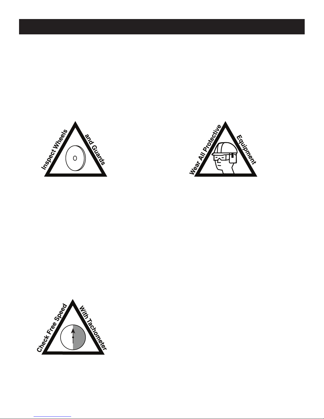
Check RPM with a reliable tachometer. Tool must run at or below speed stamped on tool.

Live Handle Parts Listing
PART DESCRIPTION
500-48 SCREW (4 REQ.)
500-54 LOCK WASHER (4 REQ.)
650-34 SCREEN BASKET
652-1 BARE LIVE HANDLE
652-5 SAFETY LOCK
652-6 SAFETY BUTTON
652-14 TRIGGER
652-15 O-RING
652-21 ISOLATOR
652-47 THROTTLE VALVE ASSY.
652-48 INLET BUSHING
PART DESCRIPTION
652-49 PIN
652-50 THROTTLE LEVER PIN
652-51 SPRING
652-52 SPRING
652-53 SAFETY BUTTON SPRING
652-54 SNAP RING
652-70 LIVE HANDLE WRAP
HANDLE ASSEMBLIES
AA-652-1K LIVE HANDLE ASSY.
Governors
The governors are warranted for the life of
the tool. (Execpt in cases of abuse)
Please return the governor to the manufac-
turer for warranty repair or replacement.

Tool Parts Listing
PART DESCRIPTION PART DESCRIPTION
N2 CYLINDER GUARDS
N6 BLADE (3 REQ) NRA-727 7” TYPE 27 GUARD
N70 GOVERNOR SEAT NRA-927 9” TYPE 27 GUARD
NRA-1-A ANGLE HEAD NRA-1041 10” TYPE 1 GUARD
NRA-4-250 OUTER FLANGE
NRA-7 FRONT ENDPLATE TOOLS
NRA-8 FRONT MOTOR BEARING 1100-151 1” OPEN-END WRENCH
1100-150 1 - 1/2” OPEN-END WRENC
51254 3/16” HEX KEY, LONG ARM
NRA-9 REAR OUTPUT BEARING
NRA-10 GEAR SET
NRA-13 SHIELD
NRA-14 SNAP RING
NRA-15 SPACER
NRA-16 FRONT OUTPUT BEARING
ASSEMBLIES
AA-652-1K LIVE HANDLE ASSY.
NRA-17 SPINDLE-5/8-11 X 1.1” LONG
NRA-20 SPINDLE LOCK HOUSING
AA-NRA-20 SPINDLE LOCK ASSY.
NRA-21C SPINDLE LOCK PIN
AA-NRA-130 MOTOR CASE ASSY.
NRA-22 SPINDLE LOCK SPRING
NRA-24 LOCK BUTTON
GOVERNORS
NRA-27A EXHAUST DEFLECTOR
NGOV-63 6000 RPM GOVERNOR
NRA-40 DEAD HANDLE
NRA-42 DRIVE FLANGE
NRA-43 KEY
NRA-130 MOTOR CASE (SPECIFY SPEED)
NRB-5 ROTOR
NV-3 REAR ENDPLATE
NV-9 REAR MOTOR BEARING
400-44 PIN
500-25-G GREASE FITTING
550-86 TYPE 28 GUARD EXTENDER
550-87 NUT
661-30 NUT
700-34 NUT
700-46 LOCK WASHER (4-8 REQ)
700-47A SCREW (4 REQ)
594030 O-RING
594228 O-RING

The following suggestions will help reduce or moderate the effects of repetitive work motion and/or
extended vibration exposure:
1) Do not over-grip the machine/tool. Use only the force required to maintain control.
2) Keep hands and body dry and warm. (Blood flow is important - exercise hands and arms as
often as necessary.)
3) Keep wrists as straight as possible. (Avoid hand positions that require the wrist to be flexed, hyper
extended or turned side-to-side.)
4) Avoid anything that may inhibit blood circulation such as smoking tobacco or cold temperatures.
5) Do not support body-weight on the tool during operation.
6) Maintain a stress-free posture for the entire body.
Prolonged exposure to vibrations created by vibrating sources may cause health hazards. There are
gloves, handle wraps and other forms of protective measures available to help reduce the hazard. The
fit and condition of any vibration abatement measure must be monitored.
Ergonomics - Work Healthy
Guarding
Always make sure the wheel guard is positioned between the operator and the wheel. Flying debris
from the workpiece and/or the wheel can cause a hazard. The guard should be positioned so to
deflect debris from the grinding surface away from the operator. The diagram below details the
proper positioning of the guard to protect any handles the operator might grip and the area where
the operator stands.
Area of
Protection Area of
Protection

Following the guidelines will help you to ensure the pneumatic tools your company uses are operating and are
maintained in the very best of condition.
Initial Inspection of a New Tool
When a new tool is delivered to your facility, it is important to inspect the tool for any signs of damage that may
have occurred during shipping. Here is a list of things to inspect:
● With the tool disconnected from the air supply, depress the throttle lever or trigger. The device should move
freely and not become caught.
● Inspect the guard of the tool, if so equipped. The guard should be free of any chips, nicks or dents.
● Inspect the spindle of the tool. The threads should show no signs of bends or chips. Grasp the spindle by
hand and spin. The spindle should turn freely with no resistance.
Plumbing Installation
The tool must have fittings and connectors installed into the air inlet in order to connect with your companies
air system. Your choice of fittings can greatly affect the performance of the tool.
Fitting Size
The size of the air inlet of the tool is the minimum size of fitting that will allow for proper airflow into the tool.
Should a smaller fitting size be used such as reducers or adapters, this will constrict the
airflow into the tool and reduce the overall performance.
Coupling Size and Installation
The coupling size should be equal to or larger than the inlet size of the tool. If a smaller size coupling is
used then the air supply volume may be reduced which may lead to reduced performance from the tool. The
coupling should be installed near to the tool. It is important that the tool receive internal
lubrication on a regular basis. Having the connection closer to the tool will promote regular lubrication, as the
connection is easily accessible. Hose whips are often used between the tool and the coupling.
Use thread sealant on all pipe threads and ensure a tight fit.
Operating Speed Test
After your initial inspection and installation of the plumbing connections, it is important to test for the operating
speed of the tool. This test should be performed before you install any abrasive or tooling. Each tool is
stamped with a maximum operating speed. This speed determines the highest rotational speed in R.P.M.’s
that the tool will turn when it is functioning properly. This speed was set from the factory and is closely related
to the operating speed of the abrasive used with the tool. This relationship will be discussed in the “mounting
abrasives” section.
Find the maximum operating speed stamped onto the tool. Connect the tool to an air supply that
provides 90 psi and secure the tool in a vise. A lower or higher air pressure will result in a false speed
test and may create a hazardous situation. Depress the throttle lever or trigger and run the tool. Use
a properly calibrated tachometer to determine the actual operating speed of the tool. The actual
operating speed on the tachometer should be 90-95% of the maximum free speed stamped on the
tool. If this is not the case then contact the distributor or tool manufacturer immediately. The tool must
not be put into service if the actual speed is over 95% of the stamped maximum speed.
Example: Tool rated at 6000 R.P.M.
90% of 6000 (.90 x 6000) = 5400
95% of 6000 (.95 x 6000) = 5700
The tool should run between 5400 and 5700 when tested with a tachometer.
Installation and Maintenance Tips

Mounting Abrasives
The mounting of the abrasive used with the tool is very important to ensure safety for the operator and proper
functioning of the tool. There are strict rules for mounting wheels that are outlined in ANSI B7.1-2000. The
following diagrams briefly describe the methods and equipment for mounting most abrasives.
Each wheel/mounted stone is labeled with a maximum operating speed. It is extremely important to compare
this rating with the maximum operating speed of the tool. Never mount a wheel on a tool where the maximum
operating speed of the tool is higher than the maximum operating speed of the wheel. This can cause an over
speed situation and can result in injury.
The following list details specific items one should inspect and be aware of when mounting abrasives.
● The maximum operating speed marked on the wheel must be equal to or higher than the rated spindle speed
(free speed) of the tool.
● Check the wheel dimensions so that it fits within the guard properly.
● Do not use any wheel that shows cracks, chips or evidence it has been soaked in fluids.
● Wheel flanges should have flat contact surfaces and be without cracks or burrs.
Testing the Mounted Wheel
Start any new grinder with a new wheel under a bench and away from any bystanders. Run at full speed for
one minute.
Type 27 Wheel w/ Built-In
Wheel Flange
Type 27 Wheel w/o
Wheel Flange
Spacers , backing plate,
retaining nut and hex
wrench are used with this
mounting method
CP-53
CP-51
CP-53
RIGHT ANGLE TOOL FOR
USE WITH TYPE 27 WHEELS

Ensure Proper Pressure, Filtration & Lubrication
Properly lubricated pneumatic tools work better, last longer between maintenance intervals and are safer in
general use. The maintenance costs are reduced dramatically when a little time is taken to regularly lubricate
the tools. There are several ways to ensure proper lubrication.
1) Filters, Regulators & Lubricators
These devices should be installed in the air system at each grinding station and inspected regularly to ensure
proper operation. Each device in this set performs a vital task that greatly affects the performance of the tool
and overall longevity of the component parts.
Filters
A filter is a device used to trap/contain particulate and liquid contaminants in the compressed air system. They
generally have a cartridge or screen that requires cleaning or replacement regularly. Without this maintenance,
the filtering device can become clogged and reduce the flow of air to the tool. A loss in performance can result.
Regulators
A regulator adjusts the operating pressure supplied to the tool. This device generally is used with a pressure
gauge that will indicate the current pressure setting. All Top Cat ® pneumatic tools are designed to operate at
90 PSI (6.2 bar) while the tool is running. The tool should never be run if the pressure should exceed 90 PSI
(6.2 bar).
Lubricators
Lubricators are devices that induce a controlled amount of oil into the air supply for pneumatically driven tools.
They generally contain a reservoir that one must keep filled with oil. A light grade oil such as Mobil DTE light
or equivalent is recommended. There is a variable setting on the lubricator that will determine the amount
of oil induced into the air supply. It is important to inspect both the setting and amount of oil in the lubricator
regularly to determine proper functioning of the device. The lack of oil in the air system will greatly reduce the
performance and longevity of the pneumatically driven tool.
NRA-42
NRA-4-250
661-31-RH
Type 1 Cut-off
(Type 41) Wheel
RIGHT ANGLE TOOL FOR
USE WITH TYPE 1 CUT-OFF
(TYPE 41) WHEELS

© Copyright 2013 All Rights Reserved
2) Direct injection of oil into the tool
A simple and easy way to ensure proper lubrication is to inject the oil directly into the tool air inlet. This should
be performed prior to storage of the tool. To perform this task one must have a small container of the proper
lubricating oil.
●Disconnect the tool from the air supply at the air coupling.
●Place a few drops of oil from the container into the air inlet of the tool directly.
●Reconnect the tool to the air supply.
●Direct the exhaust of the tool away from any bystanders or cover the exhaust with a shop rag.
●Run the tool until the oil has completely passed through the unit.
The best lubrication techniques include both methods.
What Conditions Indicate the Need for Maintenance?.
Pneumatic tools will exhibit several distinct signs that maintenance is required. Higher costs can be avoided
if maintenance is performed when the first signs are evident. The following list details conditions that may
indicate the necessity for service.
1) With the tool disconnected from the air supply, grasp the spindle and spin in the direction of operation. The
spindle should spin freely with no resistance.
2) With the tool disconnected from the air supply, grasp the spindle by hand. Attempt to move the spindle from
side to side and back and forth. Excess play can be a sign that service is required.
3) A reduction in power may indicate the necessity for maintenance.
4) Should the tool not maintain a uniform operating speed, servicing may be required.
For More Information
1) General Industry Safety & Health Regulations 29 CFR, Part 1910 and where applicable Construction
Industry Safety & Health Regulations 29 CFR, Part 1926 available from Superintendent of Documents, Gov’t.
Printing Office, Washington, D.C. 20402.
2) Safety Code For Portable Air Tools, ANSI B186.1, B7.1 and Z87.1, available from American National
Standards Institute, Inc. 1430 Broadway, New York, NY 10018
Form No. CHS-OM-01
Table of contents