H&S RR 420 EVO User manual


3
TABLE OF CONTENTS
A.
INTRODUCTION
5
A.1
ABOUT THE MANUAL
5
A.2
IDENTIFICATION
5
A.3
MAIN COMPONENTS AND TECHNICAL DATA
5
A.4
WARRANTY
6
B.
SAFETY
8
B.1
GENERAL RULES
8
B.2
TRANSPORTATION, INSTALLATION AND MOVEMENT
8
B.3
INTENDED USE AND WARNING OF EMPLOY
10
B.4
REASONABLY FORESEEABLE MISUSE AND LIMIT OF EMPLOY
12
B.5
RESPONSABILITY OF THE OPERATOR
13
B.6
SAFETY LABELS
13
B.7
NOISE LEVELS
14
B.8
RESIDUAL RISKS
14
C.
INSTALLATION
15
C.1
PRELIMINARY INFORMATIONS
15
C.2
INSTALLATION TO TRACTOR
15
C.3
INSTALLATION AND ADJUSTMENT OF CARDAN SHAFT
16
C.4
HYDRAULIC HOSES
17
C.5
REMOVAL
17
C.6
STORING THE RAKE
17
D.
OPERATION AND USE
18
D.1
WORKING CONFIGURATION
18
D.2
WORKING PROCESS
19
D.3
ADAPTATION TO THE PARALLEL WINDROW ROTARY RAKE TO THE GROUND
19
D.4
ADAPTATION OF THE WINDROW TINE DISTANCE FROM THE GROUND
20
D.5
ADJUSTMENT OF THE HYDRAULIC CYLINDER MOVING
21
D.6
ADJUSTMENT OF THE SIDE DEFLECTOR DISTANCE FROM THE GROUND
21
D.7
ADJUSTMENT OF THE SIDE DEFLECTOR RANGE
22
D.8
CHANGE OF DIRECTION (U-TURN)
22
D.9
END OF THE WORK
22
E.
MAINTENANCE
23
E.1
WARNING DURING MAINTENANCE
23
E.2
MAINTENANCE TASKS
23
E.3
REPLACEMENT OF THE WINDOW TINES
22
E.4
TROUBLESHOOTING
22
E:5
MACHINE DEMOLITION: DISPOSAL OF MATERIALS
24
ASSEMBLY INSTRUCTIONS
27
PULL-TYPE ASSEMBLY
28
MOUNTED ASSEMBLY
43
SERVICE PARTS - MOUNTED TYPE
60
SERVICE PARTS –PULL-TYPE
72
SPARE PARTS FORM
93

4

5
A. INTRODUCTION
A.1 About the manual
The H&S firm (“Manufacturer”) designed and
created the device in accordance with the
associated safety standards to ensure the safety of
personnel and the entire operating system.
Each rake is supplied with a copy of this manual
which the operator must read in full before using
the equipment. The manual contains all information
relating to transportation, use and maintenance of
the equipment, as well as safety instructions.
Poor knowledge of the operating system can lead
to accidents and therefore damage to the
equipment. Although the Manufacturer provides the
Customer with all information relating to the rake
operation, use and maintenance, the Customer is
still expected to read this manual and take note of
all the instructions herein.
The manual provides all the necessary instructions
on how to ensure optimal working order and safety.
The manual was drawn up according to the current
technical and structural characteristics of three
models of rake and does not cover previous similar
models. The Manufacturer therefore reserves the
right to modify models in production in the interest
of improvement or due to any new legislation
(Machinery Directive), without being obliged to
modify previous models.
This manual is integral to the rake and must
therefore be kept intact, clean and in good
condition. It should also be in a container, either on
the frame of the rake or in the tractor cabin, where it
can be easily accessed for consultation.
The manual must be kept in its container if the rake
is taken out of service. Ask the Manufacturer for a
duplicate copy if the original manual is lost.
Please contact the H&S Dealer for any clarifications
relating to the instructions in this manual.
Symbols used in this manual:
HAZARD
Indicates an imminently hazardous situation
that, if not avoided, will result in death or
serious injury.
WARNING
Indicates a potentially hazardous situation that, if
not avoided, could result in death or
serious
injury. It is also used to alert against unsafe
practices.
CAUTION
Indicates a potentially hazardous situation that,
if not avoided, may result in minor or
moderate
injury. It is also used as a reminder of good
safety practices.
IMPORTANT
The operator must take the respective information
into account.
Note indicates that the information referred to can
facilitate the operator work.
A.2 Identification
An identification plate is applied to each machine:
You must have this information at hand when
requesting assistance and spare parts.
IMPORTANT
It is strictly forbidden to alter and/or eliminate the
data on the serial plate. The operator must check
the legibility of the data on a regular basis and
inform the Manufacturer if it becomes in any way
illegible. The Manufacturer will then replace the old
plate with a new one bearing the same data.
A.3 Main components and technical data
1. Three-point hitch
2. Cardan shaft attachment
3. Steering damper spring
4. Lateral protection screens
5. Working rotate unit
6. Tine-holder arm
7. Lateral deflector
8. Wheels
9. Windrowing tines
10. Arm-holder supports
11. Frame
12. Bearing foot
13. Adjusting lever of tine height
14. Tow hitch
Type: XXXXXXXX Model
Serial N. XXXXXXX-XX
MFG: 2015 DEL: 2015

6
MOUNTED TYPE PULL-TYPE
A4 Warranty
H&S (called Manufacturer) guarantees every
component of the windrow rotary rake is without
defects, as they are tested before delivering the
machine to the Customer. The warranty has a 1
year validity starting from the date indicated
on the tax delivery document, except
different agreements underwritten with the
Customer.
However, upon receipt of the windrow rotary
rake, they must verify that it is intact and
complete in its every part. Any claims must reach
the Manufacturer in writing within 8 days from
receipt of the equipment.
H&S commits to replace the components that,
for manufacturing or material defects, cause a
fault in the operation at its establishment, within
the warranty period and free of charge. Should it
not be possible such replacement at its own
premises, the Manufacturer commits to sending
the faulty pieces at the Customer's premises.
With regard to these replacements, H&S does
not waiver the warranty period during the time
which the windrow rotary rake remains still, or
recognises any damage or indemnity to the
Customer, for direct and indirect expenses or
damages. Should the intervention of our
technician be required, the relative labour, travel
and overnight expenses will be fully charged to
the Customer. Only the Manufacturer or its
technicians can ascertain the fault.
However, it must be taken into consideration
that:
the faulty pieces remain the property of the
Manufacturer;
should replacement be carried out at the
Customer's establishment, the faulty pieces
must be returned and, therefore, sent to the
Manufacturer, for subjecting to technical
review, integrates without tampering, without
tampering and carriage paid;
TECHNICAL FEATURES
RR 420 EVO
MOUNTED
RR 420 EVO
PULL-TYPE
Transport width
cm.
170
170
Working width with windrow
cm.
400
400
Windrow width
cm.
80
80
Tine-holder arms
nr.
11
11
Double tines
nr.
4 / 44
4 / 44
PTO
rpm
540
540
Trator power
Hp
30
30
Tractor speed in working phase
km/h
15
15
Cardan shaft + torque limiter
Nm
600
600
Tires - Ballon 18”- 8.50”x8”
nr.
4
4
Weight
kg
625
600
12
11
10 9
87
6
45
34
2
1
13
12
13
14

7
in case faulty pieces cannot be returned to
the Manufacturer within 30 days, from date
of receiving the new ones and with the
methods described in the previous point, the
Manufacturer reserves the right to sending
an invoice for the new delivered pieces.
The warranty is not recognised:
during transport as the windrow rotary rake
travels under Customer responsibility;
when faults derive from improper or incorrect
use of the windrow rotary rake or operator
negligence;
when faults are caused by normal wear,
even with the windrow rotary rake not
working;
in case of late signalling of the
manufacturing defects;
in case of accidents or fortuitous cases of
force majeure.
The warranty becomes void in case:
the windrow rotary rake is used by non-
appropriately trained personnel;
the indications and/or regulations in these
instructions have not been followed or
complied with;
the envisioned maintenance interventions
have not been carried out;
the Customer makes modifications to the
windrow rotary rake without the written
authorisation of the Manufacturer or tampers
with the components;
non-original spare parts are used or non-
conform to those recommended by the
Manufacturer.
However, the warranty period recognised for the
windrow rotary rake is not valid for all
components that are not produced by the
Manufacturer and for which that reported in the
relative purchase notes remains valid.
IMPORTANT
The Manufacturer does not guarantee conformity
of the windrow rotary rake with the legal
dispositions in force and, in particular, with those
relating to accident-prevention and pollution in
the non-E.U. Countries. The adaptation of the
windrow rotary rake to the respective regulations
will be the full responsibility and at the expense
of the Customer. The Manufacturer is relieved
from every responsibility, if the inobservance of
these regulations raises controversies or causes
any damage.

8
B. SAFETY
B.1 General rules
This manual describes the safety regulations to
be followed when using the rake. As most work-
related accidents occur due to non-compliance
with the most basic of safety regulations, it is
mandatory to read this manual before using the
rake and to follow all the instructions.
In its use the equipment must be used by
qualified adult personnel trained. The
Manufacturer cannot be held liable for
accidents due to the operator's negligence
and/or non-compliance with the safety
instructions. In this case the Manufacturer
assumes no responsibility and the warranty
is forfeited.
B.2 Transportation, Installation and Movement
Transport (delivery): This operation is carried
out by a vehicle with dimensions and weight
suitable to the equipment. Load and unload
operations from the vehicle can be done either
by using a lifting device or by using appropriate
ramps hooked to the vehicle:
- In the first case, the vehicle must have
suitable features and slings to support the
windrow rotary rake. Trained personnel will
carry out the operation by holding the
equipment in the indicated sections on the
frame, set for this purpose. - Note: to protect
the integrity of the frame, it is recommended
to not handle the windrow rotary rake with
metal chains, but to use approved belts.
However, an adhesive label
has been applied to the
points where it should be
fixed or sling should pass
through, containing a hook
(as in figure), to highlight its
use.
- In the second case instead, by using a forklift
truck or a tractor, the equipment is pushed in
reverse to the vehicle loading surface.
In both cases, the equipment must be in
compliance with the transport configuration
(forward described) and, once placed on the
vehicle, it must be fastened to its structure and
provided with all the safety devices required for
transportation.
HAZARD
Load and unload operations always entail
dangerous situations, thus requiring the
operators in charge to be very careful.
However, it is recommended to always observe
the following precautions:
-operations must always be carried out on an
even surface and by respecting a safe
distance from escarpment or ditch borders;
-ensure ramps are robust enough to support
the windrow rotary rake, that are firmly
fastened to the vehicle structure, parallel
between them and perpendicular to the
vehicle side;
-ensure ramps are clean, without any trace of
oil, grease or ice;
-do not change direction during
ascent/descent operations of the windrow
rotary rake on ramps. Should the path must
be changed, take back the equipment and
proceed with its correction.
For long distances, the equipment is transported
dismounted inside a wooden box. Once the
components are delivered, detailed instructions
allow the Customer to easily and rapidly
assemble the windrow rotary rake. So in the
event the equipment is sold or transferred to
another user, follow the instructions in the
reverse order to dismount it.
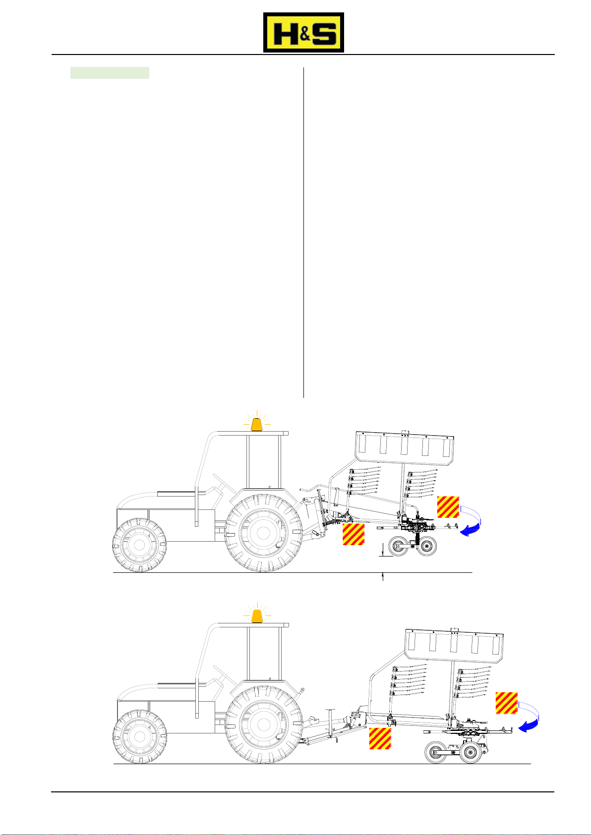
Installation: the pull-type model windrow rotary
rake can be installed on any agricultural tractor,
provided with a tow hitch and rear auxiliary
hydraulic couplings; whereas the mounted one
can be installed on any tractor provided with rear
universal 3-point hitch and of coupling and
hydraulic lift.
IMPORTANT
The tractor must also, by law, be fitted with a
protective Roll-bar or ROPS or FOPS cabin. It is
strictly forbidden to install the equipment on
a tractor without the required protection
equipment.
However, before installing, the Customer must
consult the relative use and maintenance manual
to ensure the tractor has the necessary
requisites for the windrow rotary rake use and
function and/or is equipped with ballasts to
eliminate any unbalances that might cause its
overturn.
For instructions relating to the installation of the
windrow rotary rake and any hydraulic
connections, consult the relative paragraphs. For
information relating to the cardan shaft, follow
those attached to the accessory.

9
Moving on road: pull-type windrow rotary rake
can be moved on road only if it is connected to
the towing hook; whereas the mounted one
must be lifted by using the hydraulic lift, until the
lowest section results at 40/50 cm from the
ground. In both cases, the following obligations
must be complied with:
-rear overall dimensions: the operator must
apply special panels to the windrow rotary
rake (either if it is mounted or pull-type), to
highlight the tractor rear dimensions. They
must be applied on the three visible sides
and be retro-reflecting and fluorescent with
yellow and red stripes, and be approved.
Moreover, transversal dimensions of the
equipment must never be higher than the
tractor's shape and therefore, it must always
assume the set transport configuration
(with side protection screens closed and
teeth-holder bar removed) as indicated in the
fig.4.
-signaling devices: the tractor must be
mandatory provided with the light flashing
device (yellow or orange) always operating.
Moreover, visual signal and lighting devices
of tractor must be repeated or moved if
dimensions of the windrow rotary rake do not
allow visibility. In this case it will be
necessary to install on the equipment rear
part a special light bar;
-weight: the total mass of the machinery
(tractor with windrow rotary rake) must not
exceed 30% above the normal mass of the
tractor, indicated on its vehicle registration.
The tractor must always move at moderate
speed, especially on slopes, because the
rear weight may cause loss of control;
-laws: however, it is recommended to know
and comply with laws on road circulation in
your Country.
During the machinery on-road moving (tractor
with windrow rotary rake), the operator in the
cabin must observe the following precautions:
-must not take passengers on the tractor;
-must not transport persons or animals on the
equipment;
-PTO must always be disengaged.
40 - 50 cm
MOUNTED TYPE
PULL-TYPE
Fig.4

10
Moving on fields: inside them the machinery
must not activate any luminous signal or buzzer
or display any type of panel. The windrow rotary
rake must assume the working configuration
only before operating.
Working configuration (both mounted and pull-
type - fig.5):
-one at a time, remove tine-holder arms (2)
from respective supports on frame (1) and
place them in each housings on work rotating
unit (3) to then block them by using safety pin
(4);
-first from a side and then from the other: pull
forward, towards tractor connection, the side
protection screen (6), so to unhook it from the
mechanical block (5) by using for
transportation;
-keeping it still pulled, rotate it downwards, as
indicated in figure (7), and release it only
when it is placed on the frame so to be
blocked by its relative work mechanical block
(9). When the screen (8) is released, an
appropriate spring (10) will takes it back to
the initial position. Note: on the left side of
the windrow rotary rake, the mechanical
block is not set. During the process, the side
deflector weight keeps the side screen in
position;
-for the use and the relative operating
adjustments, to consult the following
paragraph.
B.3 Intended use and warning of employ
The windrow rotary rake is an agricultural
equipment used to harvest any other type of
previously cut forage, with formation of
windrows.
The rake can be either mounted or pull-type. The
mounted type can work only if installed on any
agricultural tractor equipped with 3-point
universal hitch and hydraulic lift. Whereas, the
pull-type must be connected to the towing hook
installed behind each tractor. The operation is
common for both types and it is obtained both by
effect of the tractor towing and by effect of the
rotation of them working units. This rotation is
provided by a cardan shaft coupled to the tractor
PTO. The arm rotating motion and the action of
tines allow to realise even and well ventilated
windrows.
On the pull-type rake there are two hydraulic
cylinders, which operation allows to adjust the
tine adaptation to the ground and to lift them for
the tractor change of direction at the end of the
field or in reverse. These cylinders are powered
by the tractor auxiliary hydraulic circuit, through
hoses equipped with quick couplings and
controlled by a special lever placed inside the
cabin.
The windrow rotary rake must be used only by
adult, qualified and trained personnel and aware
of the instructions contained in this manual.
Safety is of prime importance for the personnel
who use the equipment or who perform repairs
or maintenance. Given that the provided
instructions cannot cover all possible working
situations and related danger, personnel should
always use caution and common sense.
Before starting the tractor and begin working,
it is important:
-verify that the equipment has been correctly
installed on the tractor;
-verify that all locking and safety devices are
present and undamaged;
TRANSPORT CONFIGURATION WORKING CONFIGURATION
4
567
8
910
3
1
2
Fig.5

11
-on the tractor PTO, verify that the rpm is of
540 and that it rotates clockwise. Moreover,
ensure it is disengaged.
IMPORTANT
PTO must never be engaged with the
engine off and with an inclination higher
than 10° between joints of the two
connections (tractor/windrow rotary rake
- fig.6);
-verify that the cardan shaft is correctly
installed and all blocking and safety devices
are present and undamaged. Should one
of these be not installed or non-approved
devices be mounted, the Manufacturer
warns the Customer to not use such
shaft because it is forbidden;
-do not use the equipment if failures or
damages are present especially on the
protective devices;
-only for the mounted type - lower slightly
the equipment to the ground by using the
tractor hydraulic lift. Avoid violent impacts,
which may provoke damages to the
structure or components;
-perform the daily maintenance tasks
(described in the relative paragraph). For
such purpose, remind that any kind of
intervention (check, adjustment,
maintenance, etc.) must be performed
with the tractor stopped, with PTO
disengaged, with its engine off;
-verify that the position of the side deflector
and of the tines in relation to the ground.
Should their adjustment be required, consult
the respective paragraph;
-verify that no people or animals go in the
dangerous zones of the equipment (shown
in fig.7), because they are not conscious of
possible dangers;
-the operation of the equipment is allowed in
good lighting and visibility conditions.
Should these conditions lack, even partially,
it is recommended to interrupt the working
process as normal safe conditions would not
be respected. Work should only be restarted
if the good visibility and lighting conditions
are restored. Do not use the equipment if
failures or damages are present.
During the working process the operator in
tractor cabin must observe the following
precautions:
-the tractor must proceed in straight line,
avoiding abrupt movements (sudden
10° max
EQUIPMENT PTO
TRACTOR PTO
DANGEROUS
ZONE
DANGEROUS
ZONE
DANGEROUS
ZONE
DANGEROUS
ZONE
Fig.6
Fig.7

12
accelerations and/or changes of direction).
The tractor speed must not exceed the
limit of 10 - 12 km/h (6.2 - 7.46 MPH);
-the operator in the tractor cabin must
never abandon the tractor leaving its
engine on. Even for short working breaks,
they must always stop the tractor, switch off
its engine and remove the ignition key from
the dashboard;
-during working breaks, the operator must
never allow non-authorised/qualified
personnel to replace him;
-before reversing with the tractor or for
changes of direction at the end of the field,
the operator must always verify that the
windrow rotary rake is not in working
configuration and that its teeth are lifted at
least 30 cm from the ground. For the
mounted type, all the equipment must be
lifted by using the tractor hydraulic lift,
whereas for the pull-type the entire frame
must be lifted, by hydraulic drive, controlled
by one of the tractor circuit levers from the
cabin (see also paragraph D2.8 Change of
direction or in reverse). The equipment may
be seriously damaged if the tines are not
lifted;
-the rake operation does not produce enough
noise to allow the use of the acoustic
protections (earplugs, earphones, etc.),
instead the tractor can produce it. Therefore,
consult the use and maintenance manual of
the tractor;
-vibrations produced by the equipment that
reach the operator are of low intensity and
have a frequency that result lower than
levels tolerated by human body. However, it
is important to keep transmission bodies
and gears always lubricated. It is also
important to often verify that screws are
always tighten to avoid excessive
vibrations.
Stop immediately the working process if:
-it is near to resistant objects, such as drains,
wells, shafts, etc., as the contact may break
the teeth, which pieces can be projected
around at a very high speed;
-noisy vibrations coming from the equipment
are felt. To avoid any damages, stop the
tractor, disengaged the PTO, switch off the
engine, and, if feasible, detect and remove
the inconvenient by observing the safety
regulations;
-on the pull-type model oil leakage is
detected. Do not seek the leakage with bare
hands, but by using a cloth or protection
gloves. Under pressure oil may penetrate in
the skin causing serious infections.
B.4 Reasonably foreseeable misuse and limit of
employ
A different use from that one described in the
previously paragraph is considered improper
and therefore forbidden. In addition, the
technical characteristics of the equipment must
not be modified in any way to alter its
performance. In this case, both the equipment
warranty and the Manufacturer liability would
immediately become void
Visibility: in conditions of insufficient visibility
(fog, dust, smoke or other): it is advisable to stop
the tractor and to wait until that fog, dust or other
goes away. Operate at the same way in case of
rain.
Dangerous zone: if, during the working process,
a people or an animal go in one of the
dangerous zone (see previously paragraph), the
tractor driver must immediately stop the working
process and provide to distance the intruder. At
the same way, during the adjusting and/or
maintenance tasks, the outsiders must not stay
or move in the proximity of the equipment.
Do not use the equipment if:
- the material to cut is humid or wet. In these
conditions, it becomes sticky and it easily
gather on the tines affecting the operational
function;
HAZARD
- Its operation must take place nearby
masonries. In these cases, besides the
possibility to damage the tines, a
dangerous projection of relative residuals
may occur as well;

13
For any doubt concerning the use of the windrow
rotary rake and not mentioned in this manual
contact directly the Manufacturer.
B.5 Responsibilities of the operator
Each operator becomes liable for the damages
caused to themself, others, animals or damages
to the things if they proceed with an incorrect use
of the equipment and/or not conform to the
instructions contained in this manual.
Consequently, the responsibility of the
Manufacturer would immediately be void if
the operator:
-use the equipment in improper or incorrect
way;
-use the equipment under the effect of
alcohol, medicines, drugs or if tired or sick;
-has not been property trained or has not
read the operator instructions in this manual;
-does not respect the current road laws;
-not having previously verified the required
requirements, the coupling of the equipment
to the tractor is not suitable (different power
or characteristics to the those ones
indicated in the table of the technical data);
-has not performed the foreseen
maintenance tasks;
-has modified the equipment;
-has used non original spare parts or not
right for the model.
-do not wear radio or music headphones
while operating machine;
-wear close fitting clothing and safety
equipment appropriate to the working
process.
B.6 Safety labels
In addition to the instructions contained in this
manual, adhesive labels have been applied on
various parts of the equipment to help operators.
These labels illustrate the safety rules that
should be observed.
Fig.10
M. 20
CAUTION
To Avoid Seriuos Injury:
Read Operator's Manual before operating,
Servicing or repairing equipement. Follow all
Safety rules and instructions. (Manuals are
available from your selling dealer).
Never allow riders.
Keep bystanders away from equipment during
operation.
Operate from tractor seat only.
Keep all shields in place and in good condition.
Lower equipment to ground, stop engine,
remove key and set brake before dismounting
tractor.
Never allow children or untrained persons to
operate equipment.
1U
1E 2E 3E
2U / 3U
Esternamente su entrambi i telai mobili
Externally on both the mobile chassis
NON SOSTARE O PASSARE
IN PROSSIMITA' DELLA
MACCHINA
DO NOT STOP OR PASS
NEAR THE MACHINE
NO PERMANECER O PASAR
CERCA DE LA MAQUINA
CAUTION
To Avoid Seriuos Injury:
Read Operator's Manual before operating,
Servicing or repairing equipement. Follow all
Safety rules and instructions. (Manuals are
available from your selling dealer).
Never allow riders.
Keep bystanders away from equipment during
operation.
Operate from tractor seat only.
Keep all shields in place and in good condition.
Lower equipment to ground, stop engine,
remove key and set brake before dismounting
tractor.
Never allow children or untrained persons to
operate equipment.
4U
4E
5U
5E
6E / 6U
Sull'albero cardanico - On the cardan shaft

14
The shape and colour of the labels vary based
on the rules. In addition to containing a danger or
prohibition sign, other rectangular labels provide
additional information about the safety rules that
must be observed. The rules illustrated by the
labels affixed to the equipment (fig.10) are as
follows:
1U - obligation to read the use and maintenance
manual;
2U / 3U - danger of hooking or entanglement.
With rotating arms, their tines may hook on to
clothes or other objects worn by personnel in
charge;
2U / 3U - danger of flying objects. Objects
presents in the operational field may be caught
and thrown by the tines. Keep a safety distance
of 20 m.;
4U - prohibition to stand or transit. It is
forbidden for persons not in charge to stand or
move inside the operational area of the windrow
rotary rake, when this is running. Should it be
necessary to move inside the operational area,
keep a safety distance (20 m). Whereas, when
the rake is in transport configuration, it is better to
do attention to the tines, which being in lifted
position and then sticking out should be a danger
for who transit near the equipment;
5U (on cardan shaft) - danger of hooking or
entanglement. With the rotation of the shaft,
clothes or other objects worn by staff may be
hooked ;
6U - verify that the rpm number set at the tractor
PTO output is of 540 rpm/min and that it rotates
clockwise.
IMPORTANT
The safety and instruction labels must be
replaced before they become illegible. If this
happens, the operator cannot use the carted
wheel rake until a new label is applied. Similarly it
is utterly forbidden to remove the safety or
instruction labels placed on the machine. In any
circumstances in which this occurs the
Manufacturer disclaims all responsibility because
the machine would not meet the safety standards
with which it was designed and manufactured.
The labels similar to these present on the
equipment are available from the Manufacturer.
Call the Customer service of H&S Dealer to ask
for replacements. It is advisable, during the
equipment delivery verify the presence and the
status of the labels.
B.7 Noise levels
The device produces little noise other than that
of its moving mechanical parts and has no
motor. Therefore, the operator does not need
any acoustic protection (ear plugs, muffs, etc.).
As for the noise produced by the tractor, to
consult the proper operator’s manual.
B.8 Residual risks
-Injury of lower limbs and/or bodily: loss of
stability when parking caused by the missed
installation of the bearing foot.

15
C. INSTALLATION
C1 Preliminary information
The pull-type windrow rotary rake can be
installed on any agricultural tractor provided with
towing hitch and rear auxiliary hydraulic
couplings; whereas the mounted type can be
installed on any tractor provided with rear
universal 3-point hitch and of coupling and
hydraulic lift. For the intervention the equipment
must be placed inside an area with flat surface,
arranged for the installation. The operator
performing the intervention must be aware of the
relative safety regulations and must work with
the utmost attention and caution.
C2 Installation to tractor
Mounted type (fig.11): the operator must
slowly approach the tractor to the windrow
rotary rake, positioning it so to facilitate its
centring.
IMPORTANT
The holes in the tractor attachment must be
aligned with those on the rake attachment
with maximum care and attention.
Once the manoeuvre is completed, the
operator stops the tractor, leaves the lift in
low position, engages the parking brake, in
case disengages the heavy pull, removes
the ignition key from the dashboard, gets off
of cabin and works as follows:
- inserts lift arms (9) in the appropriate
housings (low pins 1and 8) on the frame
of windrow rotary rake (6) and blocks
them, one by one, by using safety pins
(2);
- (should it not be present on the tractor)
places the adjustable tie-rod (3) in the
appropriate housing of the tractor 3rd-
point (“heavy pull” hole) and then fastens
it to the tractor by using the provided pin;
- loosens or tightens the tie-rod body of
the windrow rotary rake, leaving volute
(4) free, until it coincides with the
housing on equipment frame (7);
- fastens the tie-rod with pin (5), which
subsequently blocks with safety pin (6);
- once performed these operations, the
operator gets on the tractor and lifts the
equipment by activating the hydraulic lift
lever and supported by another operator
from the ground, until the PTO has the
same height of the tractor. Afterwards,
stops the tractor again, blocks the
hydraulic lift lever and adjusts the tie-rod
(by acting on his body), until the frame of
the windrow rotary rake is perfectly
vertical, then he tightens the lock nut;
- blocks the arms of the hydraulic lift with
the tie-rods or chains they are equipped
with.
Once performed the centring, the same
operator lifts bearing foot (12 - fig.12) in a
more suitable and safe position, both for the
transport phase and for the subsequent
working phase. For this lifting, the operator
removes pin (11) to release locking pin (10)
and then removes the latter from the foot
holes. He lifts the foot up to the lowest hole,
as indicated in the figure and tightens it with
the locking pin and relative pin.
6
2
8
9
1
7
54
3
12
11
10
Fig.11
Fig.12

16
1
2
3
4
6
9
57
8HOLE FOR
SAFETY
CHAIN
Cardan shaft: for the instructions concerning
to its installation and adjustment consult to its
use and maintenance manual.
Pull-type (fig.13): the operator must move
the tractor slowly to a position where the
joints can be easily aligned (1 - fig.13).
IMPORTANT
The holes in the tractor attachment must be
aligned with those on the rake attachment
with maximum care and attention.
When the tractor is near the rake hitch, turn
the lever on the bearing jack (2) to raise or
lower the rake hitch and bring it parallel with
that on the tractor. You can then insert the
locking pin (3) through the respective holes in
the attachments, as shown below, and
secure it in place with the respective safety
pin (4).
Next, turn the lever (5) on the bearing jack to
raise the latter as high as necessary to move
it from its position to that required for trailing
the rake.
To move the jack (fig.13): remove the R pin
(6), take out the handle pin (7) and take the
jack out of its housing (8). Next, turn the jack
counter-clockwise (9) as illustrated and re-
insert it in its housing. Insert the handle pin in
its new housing and fasten it with its
respective R pin.
Note: near the tow hitch there is a hole
where to connect the safety chain, which
must be successively fastened to the tractor.
The application of this chain is not mandatory
in Countries members of the European
Union, however it is in other Countries, as
U.S.A..
C3 Installation and adjustment of cardan shaft
Installation: strictly observe instructions
relative to installation indicated in its own use
and maintenance manual.
IMPORTANT
Before installing the cardan shaft, verify that
this has the requisites required for the type
and power to transmit according to the rpm of
the PTO. If required, verify also the tractor
use manual.
Should this not be used, is saying not
installed on the PTO of the tractor but only on
the windrow rotary rake one, lay the cardan
shaft on the support located on the mounted
type or on the towing bar of the pull-type.
Adjustment: the cardan shaft (both provided
with the equipment and sold as accessory)
has a standard length. So it must be adjusted
to the tractor where the windrow rotary rake
is installed. For this operation, proceed as
follows:
-remove protection devices from the
cardan shaft;
-remove the two parts that make up the
shaft and join a part to the windrow rotary
rake PTO, by clicking the spring safety
pin and the other part to the tractor PTO,
by clicking the spring safety pin as well;
-place the two parts of the cardan shaft
beside and find the minimum sliding
length (L). Should the shaft be too long,
shorten the two external plastic protection
pipes, which must have the same size,
and then the internal metallic ones.
Smudge the cut parts and lubricate the
internal parts.
IMPORTANT
When the cardan shaft is pulled out at its
maximum, the two pipes must overlap for
at least 15 cm. When it is inserted at its
maximum, the minimum gap allowed
must be 4 cm.
-remove the two parts of the cardan shaft
from their connections (on the tractor and
windrow rotary rake) and assemble the
Fig.13

17
shaft, by placing a part completely inside
the other;
-join again the two ends of the cardan
shaft to the relative PTO by clicking the
relative spring safety pins;
-block the protection pipes by using
appropriate chains to prevent their
rotation both on the tractor and on the
windrow rotary rake. The overlap
between guard and cardan shaft must
not be lower than 5 cm.
Now, without activating the tractor PTO, all
the equipment can be transported to the
place of use.
Note: by using the equipment on another
tractor requires the adjustment of the cardan
shaft. Proceed following the instructions
indicated in this paragraph.
C4 Hydraulic hoses
The adjustment of the tines in relation to the
ground (which implies lowering and lifting the
entire frame, including
the work rotating unit)
is determined by the
retraction and
extension of the two
appropriate hydraulic
cylinders. These are
powered by the tractor
auxiliary circuit and so
controlled by a lever,
located in the cabin.
Thus, the tine
adjustment cannot be
carried out if previously the jack pipes (provided
with quick coupling, as indicated in the figure)
are not connected to the correspondent
connections of the tractor auxiliary circuit.
C5 Removal
To remove the rake from the tractor,
follow the above instructions in reverse order.
The hydraulic connections have to be removed
before the rake.
WARNING
Before removing the hoses, remove the
hydraulic pressure inside the circuit by
acting the corresponding lever in cabin.
C6 Storing the rake
The Customer must set aside a large and easily
accessible area on his premises where the rake
can be stored. How to store the rake:
- if not already done, have the windrow rotary
rake assume the work configuration;
- park the equipment in a safe and isolated
place, on a flat and consistent surface;
- mounted type: using the tractor hydraulic
lift, rest the equipment on the ground;
- if not already done, adequately position the
support foot for the parking phase;
- remove the tractor from the windrow rotary
rake;
- protect the equipment with a sheet.
cm 5
MAX
MIN
Min 4 cm Min 15 cm
Fig.14

18
11
12
D. OPERATION and USE
D1 Working configuration
The windrow rotary rake will be driven on to the
work place, according to the regulations
described in paragraph B2 and before using the
equipment, the operator will perform the
following interventions:
- make certain that the PTO is disengaged;
IMPORTANT
Tractor PTO must never be engaged with
the engine switched off;
- only for the mounted type: by activating
the relative lever, lower the tractor hydraulic
lift until the wheels of the windrow rotary
rake touch the ground;
- switch off the tractor engine, engage the
parking brake, remove the ignition key from
the dashboard and go down from cabin;
- provide to put the equipment in the working
configuration (fig.17):
a. one at a time, remove tine-holder arms
(2) from the respective supports on
frame (1) and place them in the
housings on work rotating unit (3) to
then block them by using safety pin (4);
b. first on the right side and then on the left
one: pull forward the side protection
screen towards tractor connection (6),
so to unhook it from the mechanical
block for transportation (5);
c. keeping it also pulled, rotate it
downwards, as indicated in figure (7),
and release it only when the same is
placed on the frame so to be blocked by
its relative work mechanical block (9).
When the screen (8) is released,
appropriate spring (10) will take it back
to the initial position;
d. on the left side, before lowering
completely the protection screen, open
the side deflector (fig.18). Therefore,
remove the safety pin from the pin that
blocks the deflector rotation. Remove
the pin from its housing (11) and rotate
deflector (12) of 90° upwards, as
indicated in the figure. Complete
lowering the side protection screen.
Note: on this side of the windrow rotary
rake, the mechanical block is not set.
The side deflector weight keeps the
screen position during the process;
e. make certain that the bearing foot is in a
safety position. It must be already in this
4
567
8
910
3
1
2
Fig.17
Fig.18

19
position, because this intervention
completes the installation of the windrow
rotary rake on the tractor. Should it not
be, follow the related instructions
indicated in paragraph C2 Installation to
tractor;
-make certain that there are no persons or
animals within the action range of the
equipment, otherwise move them away;
-get up on the tractor, start the engine,
disengage the parking brake and engage
the PTO.
D2 Working process
Harvesting process starts when the tractor
moves forward and with the work rotating unit in
operation. By brushing the ground, tines scrape
the surface and collect the cut forage, forming a
left side windrow, which is regular and even, as
indicated in the fig.20. In order to obtain a
satisfying result, the windrow rotary rake must
work in parallel to the ground and tine adjusted
at a distance of 10 ÷ 20 mm from the ground
(fig.19). Instead, the side deflector position
determines the windrow width.
Proceed for some meters and then verify the
process result. Should the operator require one
or more adjustments, follow the instructions
indicated in the relative paragraphs.
IMPORTANT
Except when otherwise written, all adjustments
must be performed with the tractor engine
switched off, PTO disengaged, parking brake
engaged and ignition key removed from the
dashboard.
D3 Adaptation of the parallel windrow rotary
rake to the ground
Perform this adjustment if the equipment does
not work in parallel to the ground.
Mounted type (fig.21): to perform such
adjustment, activate the adjustment tie-rod,
located between the tractor and the third
section of the windrow rotary rake, by
loosening or tightening its body and
manoeuvring the appropriate lever, as
indicated in the figure. By rotating the lever
counter-clockwise (direction A) the tie-rod
extends, pushing the equipment frame
downwards. By rotating the lever clockwise
(direction B) instead, the tie-rod shortens,
pulling the frame of the windrow rotary rake
upwards.
Pull-type (fig.22): to perform such
adjustment, activate the front jack, located
between the towing connection and the
frame, by loosening or tightening a worm
Fig.19
10 - 20 mm
TINES
Fig.21
A
B
B
A
Fig.20

20
A
B
1
2
1
A
B
5
X
Y
3
4
B
A
A
B
B
A
B
A
screw installed in it and manoeuvring an
appropriate lever, as indicated in the figure.
By rotating the lever counter-clockwise
(direction A), the equipment frame lowers,
whereas by rotating the lever clockwise
(direction B) it lifts
D4 Adjustment of the windrow tine distance from
the ground
Mounted type (fig.23): to lower the tines
and so reduce their distance from the
ground, rotate counter-clockwise the
appropriate handle (B), located nearby the
third section, as indicated in the figure. If
they touch the ground, they must be lifted by
using the tractor hydraulic lift (A), activated
by the appropriate lever located inside the
cabin. Note: in theory, to lift the tines from
the ground, the handle should rotate
clockwise, but in practice, the weight of the
rotary unit with arms does not allow this
operation. Therefore, use the hydraulic lift.
Pull-type (fig.24): to adjust the distance of
the tines from the ground, adjust the position
of appropriate adapter (3), located in its
housing, under the rotary unit, as indicated
in the figure. First, lift completely rotator unit
with arms (1), by manoeuvring the relative
tractor service lever from the cabin, and then
safely block it, by placing a piece of wood or
metal under it (2), as indicated in the fig.24,
so that the unit cannot lower in any case.
This application is required, because to
adjust the adaptor position, an operator must
work under the rotator unit. In this position,
he must remove the R-pin that blocks the
handle pin (4), extract it from its housing and
place the adaptor by sliding it vertically in its
housing, as indicated in the figure. The holes
on the adaptor and those present in the
housing are located so to easily obtain the
desired height. Once the adaptor is placed,
the operator inserts the handle pin again in
the corresponding holes and then it blocks it,
by using the relative R-pin.
Fig.23
Fig.24A Fig.24B
Fig.24C
Fig.22
Table of contents
Other H&S Lawn Mower manuals
Popular Lawn Mower manuals by other brands

F.F. Group
F.F. Group GLM 40/124 P EASY Original instructions

Montgomery Ward
Montgomery Ward TMO-33902A operating manual

Country Clipper
Country Clipper XLT C300 Operator's manual

Snapper
Snapper Comet 265X Operator's manual

Husqvarna
Husqvarna RC 318T AWD Operator's manual

Simplicity
Simplicity 1695296 Operator's manual