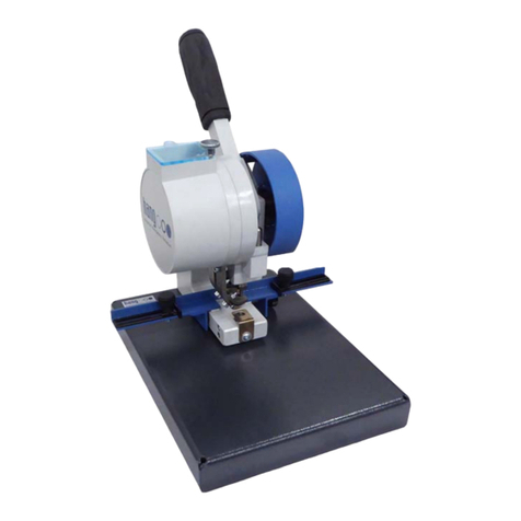
HANG 102-50 User manual

Translation of the Original Operating Instruction
Eyeletting Machine
Model 102 - 50
Part no. 706 - 0043
Eyelet 24 / 25
For future use, take note
and keep on hand with
the Eyeleter.
Maschinen - Produktion GmbH
Jahnstraße 82
D - 73037 Göppingen
Telefon +49 (0) 7161 / 6005-0
Telefax +49 (0) 7161 / 6005-78
http://www.hang.de
https://www.oesen-hang.de

Constantin Hang Maschinen-Produktion GmbH
Hang OM Automatic eyeletting machine 102-50 1
Your help is important to us:
We endeavour to continuously improve our products and their design safety. This also includes the
operating manual.
Please inform us about any deficiencies or errors that you may notice in relation to our products.
English edition, as of February 2021
Constantin Hang, Maschinen-Produktion GmbH, Jahnstraße. 82, D-73037 Göppingen
This manual has been printed on reduced-chlorine bleached, wood-free paper.

Table of contents
2 Automatic eyeletting machine 102-50 Hang OM
1 Table of contents
1 Table of contents ......................................................................................................... 2
2 Introduction .................................................................................................................. 4
2.1 Eyeletting machine equipment .............................................................................................. 4
2.2 Explanation of symbols ......................................................................................................... 4
3 Safety regulations ........................................................................................................ 5
3.1 Basic safety regulations ........................................................................................................ 5
3.2 Intended use ......................................................................................................................... 6
3.3 Safety information ................................................................................................................. 7
3.4 Workstation ........................................................................................................................... 7
3.5 Authorised operators............................................................................................................. 7
3.6 Emergency procedures ......................................................................................................... 7
3.7 Residual risks ....................................................................................................................... 8
3.8 Protective equipment ............................................................................................................ 9
4 Transport and installation ......................................................................................... 10
4.1 Safety regulations ............................................................................................................... 10
4.2 Damage during transport .................................................................................................... 10
4.3 Interim storage .................................................................................................................... 10
4.4 Installation ........................................................................................................................... 10
5 Design and function .................................................................................................. 11
5.1 Technical data .................................................................................................................... 11
5.2 Structural design ................................................................................................................. 12
5.3 Function .............................................................................................................................. 13
5.3.1 Work procedure ............................................................................................................. 13
6 Operation .................................................................................................................... 14
6.1 Safety regulations ............................................................................................................... 14
6.2 Controls............................................................................................................................... 14
6.3 Preparation for operation .................................................................................................... 15
6.3.1 Footswitch / manual operation ...................................................................................... 15
6.3.2 Refilling with eyelets ...................................................................................................... 16

Table of contents
Hang OM Automatic eyeletting machine 102-50 3
6.4 Use during operation........................................................................................................... 16
6.4.1 Switching on .................................................................................................................. 16
6.4.2 Inserting eyelets ............................................................................................................ 16
6.4.3 Switching off .................................................................................................................. 17
6.4.4 In case of emergency .................................................................................................... 17
6.5 Changing the riveting pressure ........................................................................................... 17
6.5.1 Setup ............................................................................................................................. 18
6.6 Adjusting the stops ............................................................................................................. 21
6.6.1 Adjusting the rear stop .................................................................................................. 21
6.6.2 Adjusting the lateral stop ............................................................................................... 21
7 Maintenance ............................................................................................................... 23
7.1 Safety regulations ............................................................................................................... 23
7.2 Maintenance and inspection list .......................................................................................... 23
7.2.1 Lubrication ..................................................................................................................... 24
7.3 Cleaning the feed channel .................................................................................................. 25
8 Faults .......................................................................................................................... 26
9 Repairs ........................................................................................................................ 27
9.1 Safety regulations ............................................................................................................... 27
9.2 Tool change ........................................................................................................................ 28
9.3 Emptying storage containers .............................................................................................. 32
9.4 Changing the bristle disk .................................................................................................... 33
10 Decommissioning - packaging ................................................................................. 35
10.1 Safety regulations ............................................................................................................... 35
10.2 Preparation for storage ....................................................................................................... 35
11 Disposal ...................................................................................................................... 36
11.1 Safety regulations ............................................................................................................... 36
11.2 Procedure ........................................................................................................................... 36
12 List of images ............................................................................................................. 38
13 List of abbreviations .................................................................................................. 39
14 Glossary ..................................................................................................................... 40
15 Appendix .................................................................................................................... 41

Introduction
4 Automatic eyeletting machine 102-50 Hang OM
2 Introduction
2.1 Eyeletting machine equipment
Operating manual
Tool
Foot switch (optional)
The tool bag is included in the cardboard box which the eyeletting machine is
delivered in.
2.2 Explanation of symbols
[1] Parts numbers detailed in the images are shown in squared parenthesis. The
images can be found in the corresponding chapters. Subsequently detailed
parts which are no longer listed will be taken as read.
[7/6.3.1] In this example, component [7] is referred to in image (6.3.1).
/ – Lists are marked by means of dots or indent markings for a paragraph.
/ These symbols are used to describe actions.
This symbol is used to identify actions that are described in a different
section of the operating manual.
Arrows are used to identify automatic processes or situations that should
adjust automatically.

Safety regulations
Hang OM Automatic eyeletting machine 102-50 5
3 Safety regulations
3.1 Basic safety regulations
The eyeletting machine corresponds to the applicable safety regulations and
standards. These are listed in the Declaration of Conformity in accordance
with EC Machinery Directive 2006/42 EC.
Please also observe the national guidelines and laws as well as the accident
prevention regulations, in particular:
Electrical plants and equipment (VBG 4 in Germany)
Power tools (VBG 5 in Germany)
Riveting machines (VBG 13 in Germany)
Instruction
Individuals who are involved in the transport, installation, operation,
maintenance, repair and disposal of the eyeletting machine must be instructed
on how to perform these activities or have been trained specifically for these
activities and know the potential hazards.
We recommend that you have participation in instruction sessions confirmed
in writing by the personnel concerned. You can make use of the form in the
appendix.
Operating manual
The operating manual
is a component of the machine.
must be provided when the machine is sold or hired out.
must be stored near the machine in a location that is close to hand so it can
be used regularly until the machine is disposed of.
Faults
Never use the eyeletting machine if it is in a defective condition.
Report faults or other damage to the individual in charge immediately.
Safeguard the eyeletting machine against misuse or accidental use.
Only qualified specialists are permitted to carry out repairs.
Never bridge or bypass protective and safety equipment.
Dismantled safety equipment must
be replaced before recommissioning and
checked to ensure that it is functioning correctly.

Safety regulations
6 Automatic eyeletting machine 102-50 Hang OM
3.2 Intended use
The eyeletting machine has been designed exclusively for inserting eyelets
into unpunched paper stacks (documents / certificates).
The eyeletting machine has been designed for the domestic and
commercial sectors in accordance with EMC law.
The level of immunity to interference is too low for the industrial sector – the
machine could be destroyed.
Materials Eyelet Internal diameter of 3 mm to 6 mm
Paper
stack
Certificates ; documents ; the height of the paper stack to be
processed is based on the length of the eyelet
Any use that deviates from the conditions specified above will be considered
an improper use.
If the machine
is used incorrectly,
is incorrectly maintained or
is incorrectly operated,
the manufacturer will accept no responsibility for any resulting damage. In
this case, the user alone shall bear the risk.
Only the eyelet type for which the machine was built can be processed.
The eyelet feed with container, as well as possibly also cylinder and
punch, must be adjusted so that other eyelets can be processed.
Contact Customer Service at Hang for this purpose.
Examples of
improper use
Riveting of:
plastics,
unpunched, metallic materials and
textiles.

Safety regulations
Hang OM Automatic eyeletting machine 102-50 7
3.3 Safety information
Warning of impending danger which could lead to serious injury or death.
Caution due to an impending risk which could lead to minor injuries. This
signal word may also be used for warnings related to property damage.
For a possible situation which could lead to damage to the product or
property in its vicinity.
Indicates usage notes and other useful information.
3.4 Workstation
The worktop and chair must meet ergonomic requirements.
Subject to the scope of the work, the operator sits or stands freely in front of
the eyeletting machine when loading the paper stack.
3.5 Authorised operators
Operation:
Maintenance:
Repair:
Mechanical system
Electrical system
Disposal:
all individuals over the age of 16
Skilled workers (e.g. industrial mechanics)
Skilled workers (e.g. industrial mechanics)
Electrical specialists (e.g. industrial electricians)
Skilled workers
3.6 Emergency procedures
Press the toggle switch [7/6.2.1] and remove the mains plug.
Only ABC extinguishers may be used to extinguish fires involving the
eyeletting machine.

Safety regulations
8 Automatic eyeletting machine 102-50 Hang OM
3.7 Residual risks
The eyeletting machine is equipped with protective equipment.
However, the following residual risks are inevitable:
Image 3.7.1 Residual risks
Risk of crushing fingers with the tool.
Only ever operate the eyeletting machine when the protective hood is
completely closed [2].
Never manipulate the safety limit switch [1].
Risk of crushing fingers beneath the falling protective hood.
Close the protective hood [2] in such a way that your fingers cannot
become trapped in the housing.
Risk to life due to electric shock when carrying out repairs on switches,
cables or when the protective hood is open [3].
Prior to performing repair work, set the toggle switch to "OFF" and remove
the mains plug.
These activities may be performed by a skilled electrician only.

Safety regulations
Hang OM Automatic eyeletting machine 102-50 9
3.8 Protective equipment
Image 3.8.1 Protective equipment
Pos. Protective
equipment
Function Inspection
1 Safety limit
switch
Prevents the gear motor from
starting up when the
protective hood is open.
If the protective hood is
opened, this causes the
eyeletting machine to stop
immediately.
Weekly functional inspection
- Must be screwed down
tightly at all times
2 Protective hood Prevents access to the
danger zone
Visual inspection
- Must be closed at all
times
3 Proximity
switch
Switches the gear motor off
after each work cycle.
Self-checking
- Does not stop in the
event of a defect
- Overruns the stopping
point (continuous
operation)
4 Warning sign “Danger of death from high
voltage!”
Visual inspection
- Must be present
5 Cover plate Prevents life-threatening
contact between live parts.
Visual inspection
- Must be screwed down
tightly

Transport and installation
10 Automatic eyeletting machine 102-50 Hang OM
4 Transport and installation
4.1 Safety regulations
Risk of falling
This can result in serious injuries.
Please note the warnings on the overpack
Carry out all the tasks taking into account the "Safety regulations"
chapter.
Always use suitable transport equipment.
4.2 Damage during transport
Check the cardboard box for external damage.
Open the cardboard box.
Check that the delivery is complete and undamaged, see the section
“Equipment” in the “Introduction” chapter regarding this.
If it is apparent that there is damage due to transport or the delivery is
incomplete, report this to the forwarder or Hang immediately.
4.3 Interim storage
If the eyeletting machine has to be stored for an intermediate period, this
should preferably be done in the original packaging. The following points apply
to the storage space:
Store only in dry, indoor rooms.
Observe the chapter “Design and function - technical data”.
4.4 Installation
First of all, carefully read the chapter “Safety information” and “Operation”
of the operating manual.
Place the eyeletting machine on a table or worktop.
The distance between the eyeletting machine and the mains socket
must not exceed 2 m.
There must be enough space at the side to store the documents.

Design and function
Hang OM Automatic eyeletting machine 102-50 11
5 Design and function
5.1 Technical data
General data
Space requirement L x W x H 500 mm x 540 mm x 355 mm
Working height Dependent on the table height
Weight 36 kg
Cycle time 0.5 s
Riveting pressure max. 0.2 t
Work area
Internal diameter of eyelet 3 mm to 6 mm
Paper stack thickness Depends on length of eyelet, however, max.
35 sheets (80 g/m²)
Radius max. 60 mm
Power supply
Mains voltage 230 V
Frequency 50 Hz
Power consumption 200 W
Ambient conditions
Storage temperature -5 C° to +55 C°
Operating temperature +5 C° to +40 C°
Installation site Office premises protected against dew point,
free of dust, horizontal and even
Working height Min. 750 mm
Environmental impact
Sound pressure level 71 dB(A) peak value as defined in EN CEN TC
198 WG 3 N 14 DEF - J.11.6 - KL 3

Design and function
12 Automatic eyeletting machine 102-50 Hang OM
5.2 Structural design
Image 5.2.1 Structural design of the eyeletting machine
Pos. Structural component Function
1 Table surface Placement area for the paper stack to be punched
2 Handles Attachment points for transportation without packing
3 Feeding device Automatic feeding of eyelets
4 Protective hood Guard
5 Gear motor (hidden) Drives the eyeletting machine
6 Electrical system (switch box) Controls the sequence of operations
7 Eyeletting tool Takes up the eyelet and rivets the paper stack
8 Rear stop Holds the paper stack in place
9 Lateral stop Holds the paper stack in place

Design and function
Hang OM Automatic eyeletting machine 102-50 13
5.3 Function
The eyelets are held in the storage container of the feeding device [3/5.2.1].
This moves the eyelets out of the storage container in the correct position
and into the feed channel. The eyelets are buffered in the feed channel and
then fed to the eyeletting tool.
The gear motor drives the crank handle which, together with the rod, moves
the lever arm up and down.
The lever arm is equipped with a strap and a gear segment.
The strap transfers the force to the cylinder. At the other end of the cylinder
is the upper punch with catch pin which presses in and rivets the eyelet.
5.3.1 Work procedure
The riveting process creates a non-detachable, frictional, load-bearing
connection between the parts being joined (e.g. paper stack) by
reshaping the eyelet.
Reshaping is carried out by pressing the tool onto the eyelet.
The upper punch introduces the eyelet and cuts through the paper stack.
The lower punch reshapes the lower end of the eyelet (see image
below). The upper punch moves back and releases the eyelet
connection.
Image 5.3.1 Eyelet connection
1 Upper punch 4 Eyelet
2 Lower punch 5 Paper stack
3 Catch pin

Operation
14 Automatic eyeletting machine 102-50 Hang OM
6 Operation
6.1 Safety regulations
Check all of the safety equipment prior to initial commissioning.
The eyeletting machine may only be operated by trained, instructed
persons over the age of 16.
Carry out a test run after each change to the settings.
Carry out all the tasks taking into account the "Safety regulations"
described in chapter 2.
6.2 Controls
Image 6.2.1 Controls
Pos. Control Function
1 Lateral stop Positions the paper stack for eye punching
2 Rear stop Positions the paper stack for eye punching
3 Protective hood
(pivoting)
Safeguards the hazard zone
4 Cover
5 Palm button (fuse) Protects the motor against an overload
6 Pushbutton Triggers a work cycle
7 Toggle switch "ON" and "OFF" switch

Operation
Hang OM Automatic eyeletting machine 102-50 15
6.3 Preparation for operation
Plug the eyeletting machine's mains plug into the socket.
Fold the protective hood [3/6.2.1] up.
Adjust the rear and lateral stop [1./6.2.1] [2/6.2.1] in such a way that the
document is punched at the correct position.
6.3.1 Foot switch / manual operation
If you are operating the eyeletting machine without a foot switch, you must
connect the jumper [1] to the plug coupling [2] of the foot switch.
Image 6.3.1 Jumper for manual mode

Operation
16 Automatic eyeletting machine 102-50 Hang OM
6.3.2 Refilling with eyelets
Ensure that there are eyelets available in the storage container at all times.
Only fill up with eyelets up to the bottom edge of the container axis.
Fold the protective hood [3/6.2.1] up.
Remove the knurled screw [2] and slide the cover plate [1] to the side.
Fill the storage containers [3] no further than the container axis. Always
use the specified eyelets.
Close the filling port using the cover plate [1] and lock the cover plate with
the knurled screw [2].
Fold the protective hood [3/6.2.1] down.
Image 6.3.2 Filling port for eyelet
6.4 Use during operation
6.4.1 Switching on
Set the toggle switch [7/6.2.1] to "ON".
The control lamp in the toggle switch lights up.
6.4.2 Inserting eyelets
Push the documents to be eyeletted against the stops [1/6.2.1] [2/6.2.1].
Initiate the eyeletting process by pressing the pushbutton or the foot switch
(optional).
A work cycle takes place automatically.

Operation
Hang OM Automatic eyeletting machine 102-50 17
6.4.3 Switching off
Wait until the eyeletting machine has completed the operating cycle.
Set the toggle switch [7/6.2.1] to "OFF".
“Switching off" as described above is sufficient for breaks, the end of the
working day, weekends, and interruptions of work lasting up to a week.
Pull the mains plug out of the mains outlet in the event of longer work
interruptions.
6.4.4 In case of emergency
Press the toggle switch [7/6.2.1] (e.g. in an "emergency stop situation" or
during set-up).
The motor remains in an indefinite position.
Press the pushbutton before starting work after set-up or fault removal.
The eyeletting machine moves to its home position.
6.5 Changing the riveting pressure
Test the eye punch (as you would when “Introducing eyelets”).
If the pressure exerted by the punch is too high or too low, it will need to be
recalibrated.
Danger from operational eyeletting machine.
Risk of hand injuries.
Set the toggle switch to "OFF” before commencing work.
Secure the eyeletting machine against restarting
(e.g. remove the mains plug).

Operation
18 Automatic eyeletting machine 102-50 Hang OM
6.5.1 Setup
* Setup
“Switch off the eyeletting machine”
Secure the eyeletting machine to prevent it from restarting (remove the mains
plug).
Pull the eyeletting machine forwards so it sits approximately 130mm
beyond the edge of your work table.
Fold the protective hood [3 / 6.2.1] up.

Operation
Hang OM Automatic eyeletting machine 102-50 19
Image 6.5.1 Pressure setting
Remove the four screws [1/6.5.1] using a hexagon key.
Image 6.5.2 Pressure setting
Carefully pull the worktop [1/6.5.2] forwards, remove it and set it to one
side.
This manual suits for next models
1
Table of contents
Other HANG Industrial Equipment manuals
Popular Industrial Equipment manuals by other brands

Parker
Parker 2003-IP-00 Technical manual
Parker
Parker Aries AR-01xR Quick reference guide

Wilo
Wilo Comfort-Vario COR-1***-/VR Series Installation and operating instructions
Siemens
Siemens GAMMA instabus 5WG1 204-2AB11 Product and Application Description

L3Harris
L3Harris NARDA AMS-8061 user manual

Baileigh Industrial
Baileigh Industrial B8105 Operator's manual
