Hangzhi HIU Series User manual

1
HIU Series
High Precision AC/DC Meter
User Manual
V1.3
Founded in 2017, Shenzhen Aerospace Precision Electronics Co., Ltd. is a
technology-leading enterprise dedicated to the development, production, sales and
customization of high-precision current transducers and measuring instruments. We will
strive to build a well-known brand of precision current transducers and precision
instruments in the DC field, and become a leading international leader in precision
electronics in the field of DC systems.
Based on multi-faceted technology integration and innovation, Shenzhen Aerospace
Precision Electronics Co., Ltd. has developed the industry's first high-precision digital
current transducer and an analog current transducer featuring high precision, low costs, low
zero drift and low temperature drift. This series of products reduces industry costs,
improves industry efficiency, enhances user experience, and creates value for customers.
The company's products have won many achievements in the national innovation and
entrepreneurial competition, and won wide attention and support from all walks of life.
As a company with strong sense of responsibility and mission, we adhere to multi-point
zero-flux technology-led approach, with client-oriented service and customized products,
and improve the operating quality by successfully capital financing. We are making our
efforts to build an innovative sharing enterprise.

2
Table of content
1Preface.........................................................................................................................................3
1.1 Packing Checklist.............................................................................................................3
1.2 Accessories.......................................................................................................................4
1.3 About safety......................................................................................................................5
1.4 About label........................................................................................................................5
1.5 About measurement safety level...................................................................................6
1.6 Precautions for use..........................................................................................................7
1.6.1 Inspection before use ...........................................................................................7
1.6.2 Placement environment........................................................................................8
1.6.3 Placement method................................................................................................8
1.6.4 Use of the instrument............................................................................................9
1.6.5 Before connecting the power cord......................................................................9
1.6.6 Before connecting the test cable ........................................................................9
1.6.7 Before turning on the power..............................................................................10
1.6.8 Before measurement..........................................................................................10
1.6.9 Before connecting the communication cable..................................................10
2Summary....................................................................................................................................11
2.1 Product summary...........................................................................................................11
2.2 Product characteristics..................................................................................................11
2.3 Product composition......................................................................................................11
3Product selection guide and technical parameters.............................................................13
3.1 Product selection ...........................................................................................................13
3.2 Technical parameters....................................................................................................13
4Instructions for use...................................................................................................................17
4.1 Steps................................................................................................................................17
4.2 Instructions......................................................................................................................17
4.2.1 Boot interface.......................................................................................................17
4.2.2 Main interface.......................................................................................................17
4.2.3 AC measurement interface................................................................................18
4.2.4 DC measurement interface................................................................................18
4.3 The usage of extension ring.........................................................................................20
5Connector information.............................................................................................................21
5.1 DB9 terminal definition(DB9 male)........................................................................21
6Dimensions................................................................................................................................22
7Maintenance and service........................................................................................................23
7.1 Calibration and repair..................................................................................................23
7.2 Instrument transportation..............................................................................................23
7.3 Replacement of parts and life......................................................................................23
7.4 Cleaning..........................................................................................................................23
7.5 Frequently Asked Questions........................................................................................23
Attachment1 Communication agreement....................................................................................25
3
1 Preface
Thank you for choosing SAPE "HIU Series High Precision AC and DC Meter". In order to
make full and lasting use of this product, please keep the manual properly. The HIU series
high precision AC/DC meter is referred as "this instrument" below.
1.1Packing Checklist
When this instrument is delivered to you, please check if any abnormalities or damages
occur during transportation before using it. In particular, please pay attention to accessories,
panel, keys and other items. In case of damage or failure to work, please contact the agent
or SAPE service center.
Please keep the packaging material for delivery properly for future transportation.
Please make sure that the contents of the packing are correct.
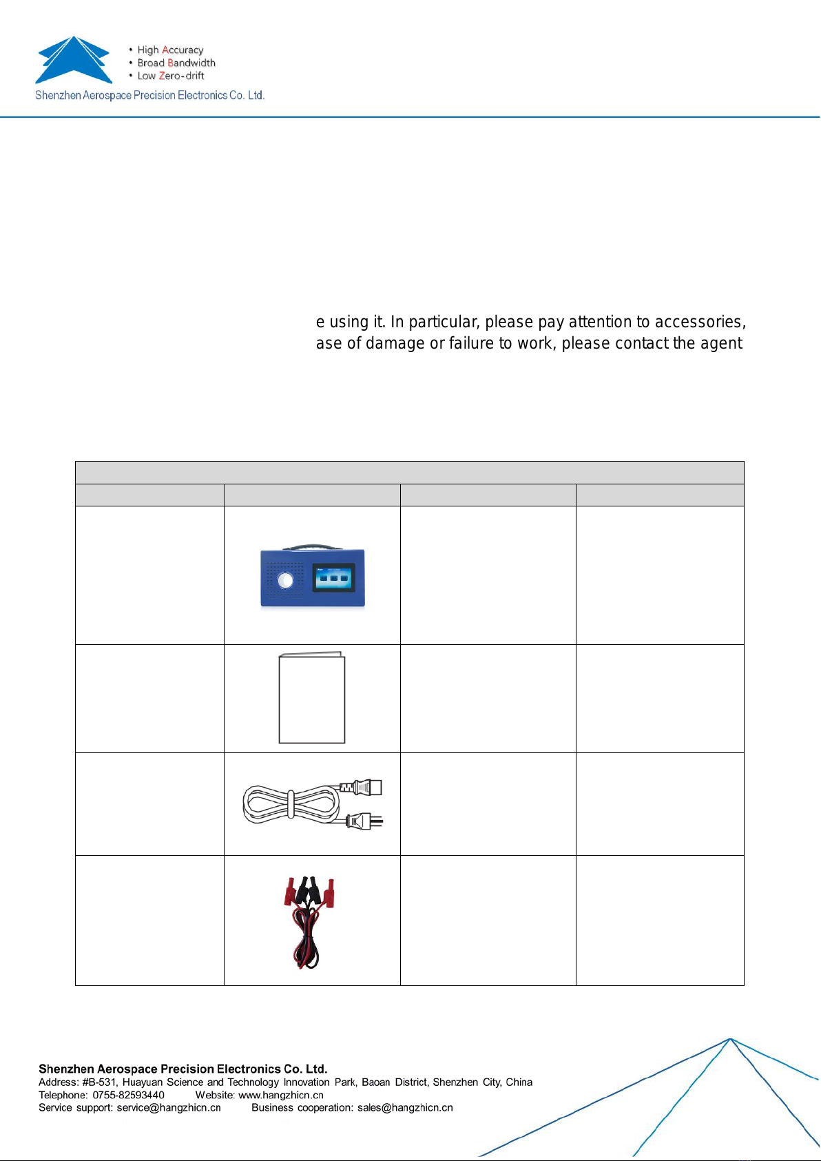
Packing checklist
Item
Product photo
Specifications
Description
□ This instrument
See Part 3
High Precision AC and
DC Meter
□ User manual(This
manual)
Soft copy or hard copy
To describe the
operational method,
specifications, etc.
□ Power line
1.5 m/3*0.75 mm2
Rated voltage:250V
Rated current:10A
For power supply
□ Voltage test line
1 m/0.8mm2
Rated voltage :CATIII
1000V/CATIV 600V
Rated current:10A
To measure the voltage
input signal
Remarks:
1) This instrument has been programmed when it was manufactured, and the latest
4
version can be downloaded from the homepage of our company
2) Instructions for use in other languages are available at our website :
http://www.hangzhicn.cn/
1.2Accessories
This instrument has the following options(to be sold separately). Please contact the agent
or sales center if you need purchase.
Option list
Item
Product photo
Specifications
Description
□ USB to RS232
connection line
1.8
m/USB2.0/RS232
It can be used to transfer PC
interface from USB2.0 to RS232
□ RS232
connection line
2 m/3*0.3mm2
DB9 Female to
female/23
connection line
It can be used to connect
between RS232 and
communication interface of this
device.
□ USB to RS485
connection line
1.5
m/USB2.0/RS485
It can be used to transfer PC
interface from USB2.0 to RS485.
□ RS485
connection line
0.1 m/2*0.3mm2
DB9 Female to
female
It can be used to connect
between RS485 and
communication interface of this
device.
□ USB
extension line
2.0 m/USB2.0/Male
to male
It can be used for LCD screen
program upgrade.
□ AC adapter
For overseas usage
Power adapter for different
countries
5
1.3About safety
The instrument is designed and tested in accordance with IEC61010 safety specifications,
and is shipped in a safe state. In addition, failure to comply with the instructions may
damage the functions provided by the instrument to ensure safety. Before using this
instrument, please read carefully the following safety-related matters.
Danger
If wrong method is used, it may lead to personal accident and instrument failure. Read the
instructions carefully and operate after fully understanding the contents.
It includes electrical hazards such as electric shock, heating, fire and arc discharge caused
by short circuit. Personnel who first use electrical measuring instruments should use them
under the supervision of senior electrical measuring personnel.
The instrument is measured under live state. In order to prevent electric shock accidents,
please wear electrical rubber gloves, electrical rubber boots, safety hats and other
insulation protective articles according to the rules of labor safety and health.
1.4About label
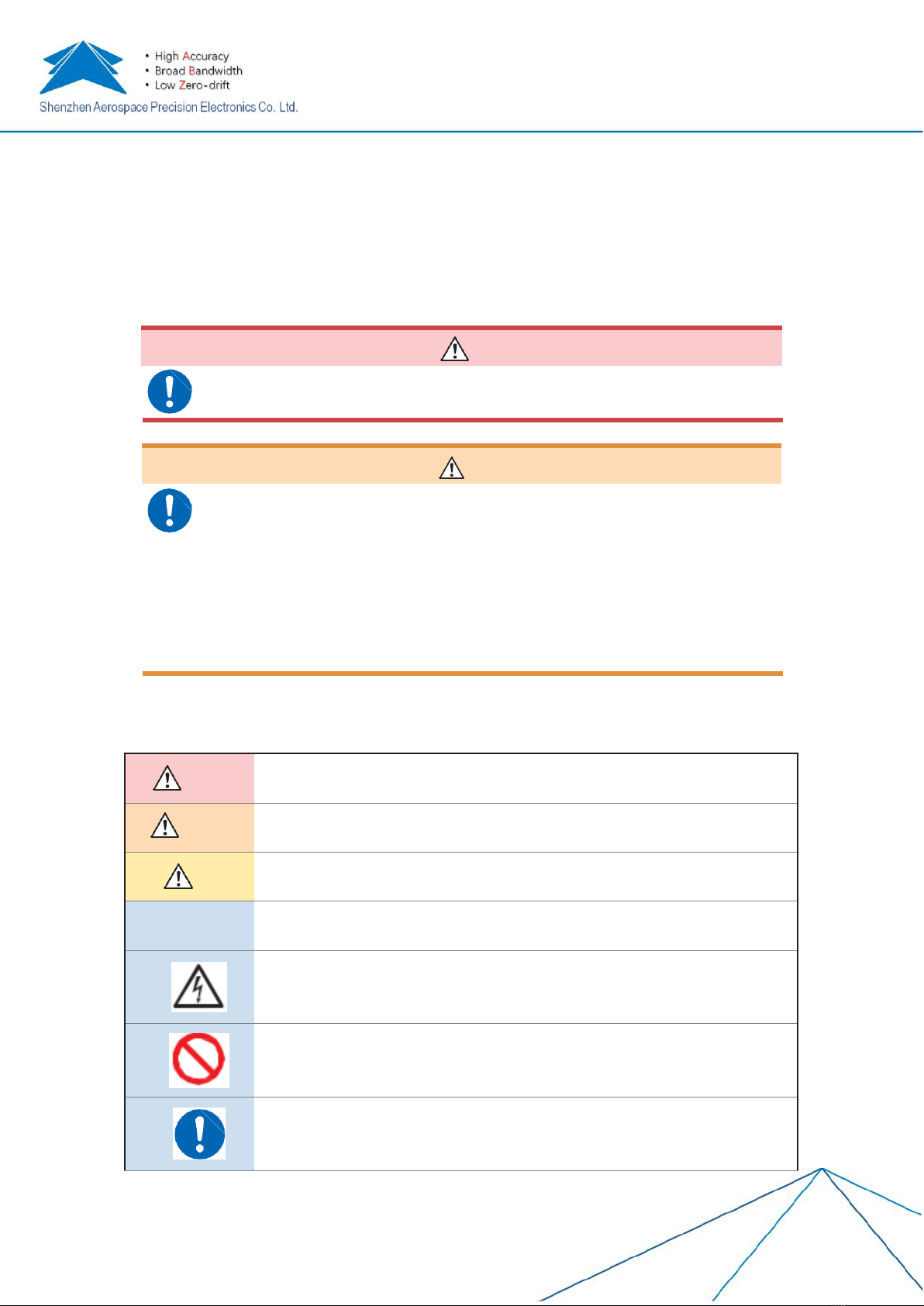
This manual classifies and marks the severity and risk levels of risks as follows.
Danger
A dangerous situation that is highly likely to cause death or serious injury to the operator
is described.
Warning
Situations that are likely to result in death or serious injury to the operator are described.
Note
Conditions that may result in minor injury to the operator or expected damage or
malfunction of the instrument are described.
Important
matters
Information or content regarding operations and maintenance work that must be known
in advance are described
An indication of high voltage hazard is used to warn the risk of shock, burns and even
death from electric shock due to neglection in safety confirmation or misuse
Prohibited behavior is indicated.
The "mandatory" matter which must be performed is indicated.
Warning
6
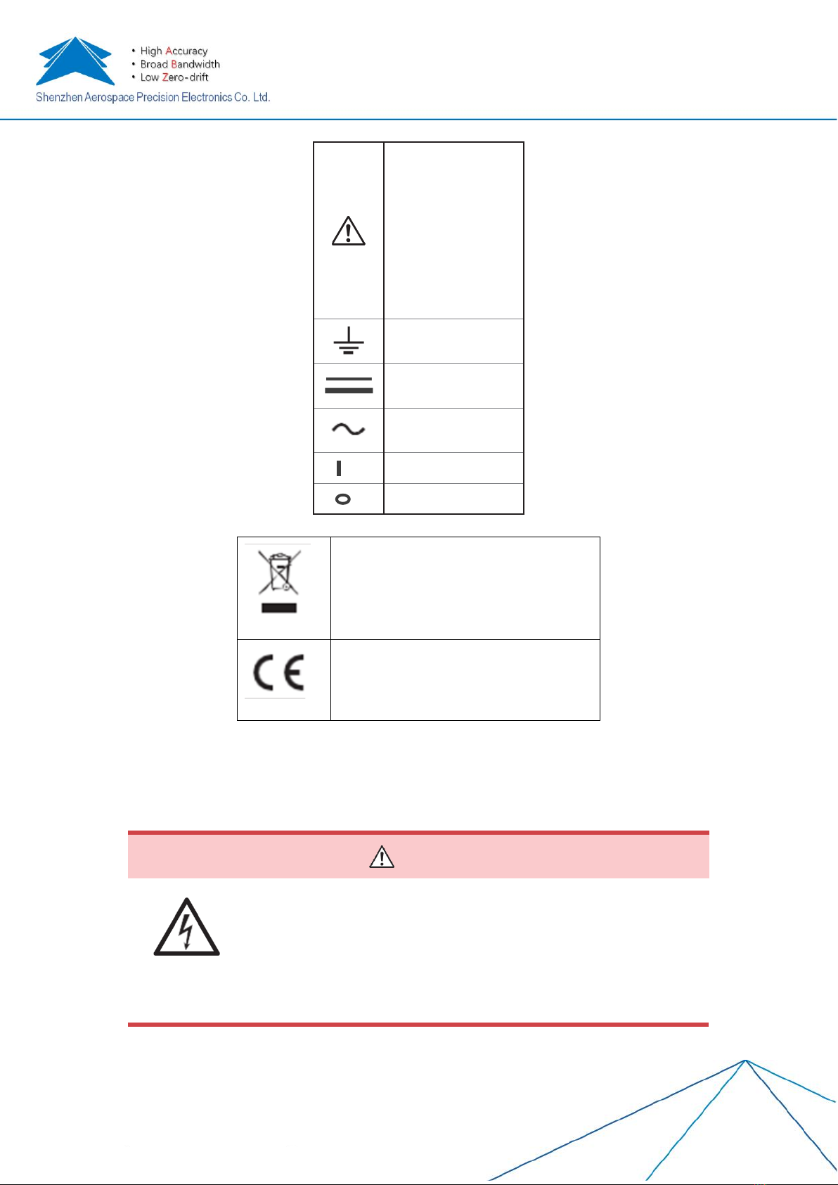
Symbol on the instrument
To indicated caution or
danger. When the
symbol is displayed on
the instrument, please
refer to the
corresponding position
in the instruction
manual.
To indicate the ground
terminal.
To denote direct current
(DC)
To denote alternate
current (AC)。
To denote power “ON”.
To denote power “OFF”.
Symbols related to standard
Marking of regulations on the
abandonment of electrical and
electronic equipment (WEEE
Directive) in EU countries.
Consistent with the restrictions shown
in the EC Ministerial Council Directive
(EC Directive).
1.5About measurement safety level
In order to use the measuring instrument safely, IEC61010 classifies the measurement into
three safety levels of CAT II to CAT IV according to the places of use.
Danger
◼Using a measuring instrument with a small classification level in
a large numerical level may cause major accidents, so please avoid
this situation absolutely
◼Using a measuring instrument without a classification mark to
measure CAT II to CAT IV may lead to major accidents, so please
avoid this situation absolutely
This instrument is suitable for CAT III 1000 V.
7
CAT Ⅱ:The primary side circuit of an instrument (movable tool, household appliance, etc.)
with a power cord that connects to the outlet, when the socket is directly
measured.
CAT Ⅲ:Measuring the primary side circuit of an instrument (fixed device) that is directly
powered from the switchboard, and the circuit from the switchboard to the outlet.
Fixtures
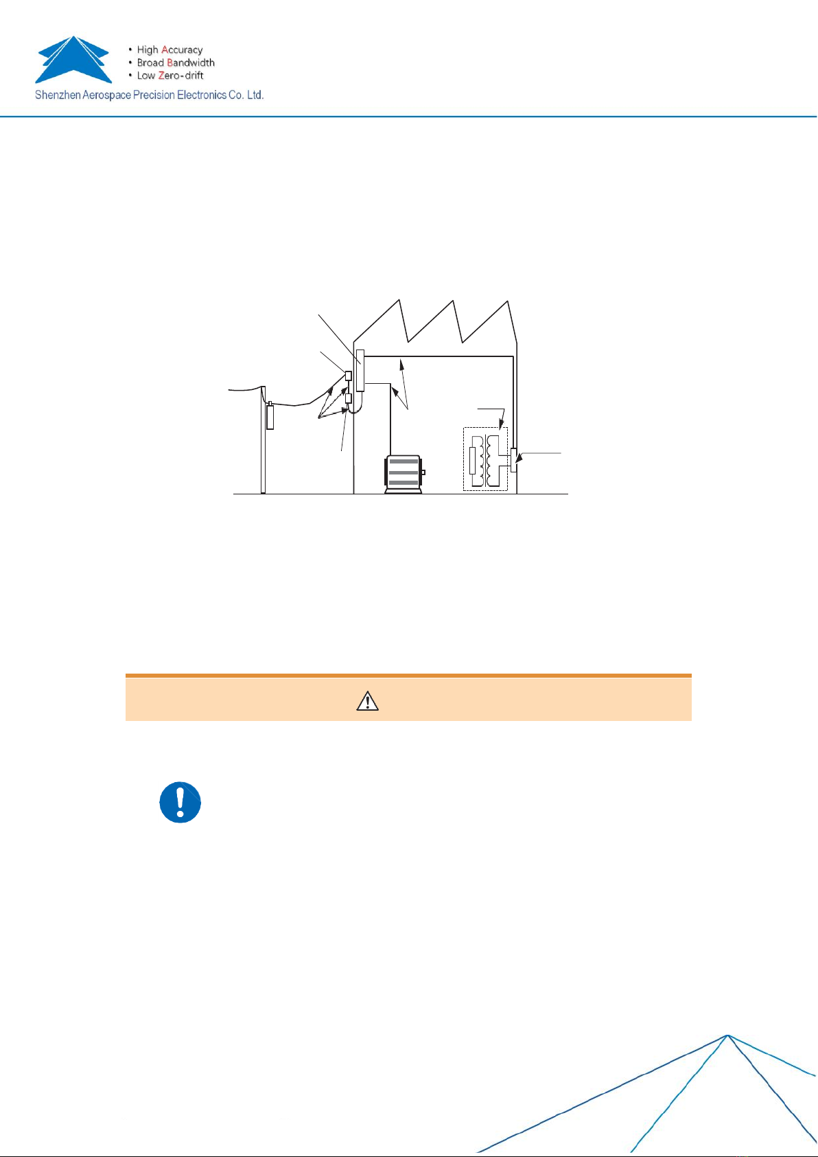
1.6Precautions for use
In order to use the instrument safely and make full use of its functions, please observe the following
precautions.
1.6.1 Inspection before use
Warning
•If the test cable or the instrument is damaged, it may cause electric shock. Be
sure to do the following checks before using it
•Before using it, please confirm that there are no problems caused by storage
and transportation, and use it after checking and confirming the operation. If it
is confirmed to be faulty, please contact the agent or the company after-sales
center.
•The outer surface of the power cord damage or exposure may cause an
electric shock or short circuit accident. Please do not use, and contact your
dealer or company after-sales center
•The outer skin of the cable damage or metal exposure may cause short circuit
or electric shock. Please replace with a device that is not damaged.
•Check whether the instrument is damaged. if it is damaged, please send it for
repair.
•When the power is turned on and the start button is lit red, the power cord may
be broken or a malfunction occur inside the instrument. Please send it for
Switchboard
Inspection entrance
Usage entrance
Internal wiring
CAT IV
Electric
meter
CATIII
CATII
T
Socket

8
Back
repair.
•After the end of the test (displaying the company LOGO), if the main
measurement function screen is not displayed, a malfunction may occur inside
the instrument. Please send it for repair.
1.6.2 Placement environment
Warning
Please do not place the instrument in the following places, otherwise it will
cause malfunction or accident of the instrument.
•Direct sunlight or high temperature places
•Locations where corrosive gases and explosive gases are generated
•Places where strong electromagnetic waves are generated or near
charged objects
•Close to induction heating device (high frequency induction heating
device, IH induction cooker, etc.)
•Locations where mechanical vibrations are frequent
•Locations affected by water, oil, chemicals and solvents
•Wet, dew condensation
•A place with a lot of dust
1.6.3 Placement method
Warning
Please do not place on unstable pedestals or in inclined places. Otherwise,
personal injury or malfunction of the main unit may occur due to falling or
tipping over.
•Place the bottom side down.
•In order to prevent the temperature of the instrument from rising, please be
sure to keep a specified distance from the surroundings when placing it.
Above 50mm Above 50mm Above 150mm
The means to cut off the power supply of this instrument is to unplug the power cord. In case of
emergency, the power cord can be unplugged to cut off the power supply immediately, so please make
sure that there is enough space for operation.

9
1.6.4 Use of the instrument
Danger
To prevent an electric shock, never remove the main unit casing, since there are
high voltage and high temperature parts inside.
Note
In order to prevent damage to the instrument, please avoid vibration and collision
during handling and use, and pay attention to collisions caused by falling.
1.6.5 Before connecting the power cord
Warning
To avoid electric shock and to ensure the safety of this instrument, please connect
the supplied power cord to a three-phase outlet.
1.6.6 Before connecting the test cable
Danger
Be sure to connect the test cable to the secondary side of the circuit breaker. Even
if a short circuit occurs on the secondary side of the circuit breaker, the short circuit
current is cut by the circuit breaker. The current capacity on the primary side is
very large, and in the event of a short circuit accident, damage to the instrument or
equipment may occur.
Warning
To avoid electric shock and short circuit accidents, please use the specified test
cable.

10
1.6.7 Before turning on the power
Warning
Before turning on the power, please confirm whether the power voltage listed on
the power connection of the instrument and the one you are using are consistent.
Using the power supply voltage outside the specified range may cause instrument
damaged or an electrical accident.
Note
Do not use UPS and DC-AC inverters with square wave or approximate sine wave
output to drive this instrument to avoid damage to this instrument.
1.6.8 Before measurement
When measuring voltage
Danger
•The maximum in-phase voltage of the voltage measurement terminal is as
follows.
CAT II :AC/DC 300 V
Without measurement classification:AC/DC 800 V
Exceedance of this voltage may cause damage to the instrument or cause
personal injury.
•The maximum input voltage of the voltage measurement terminal is DC 1000 V、
1100 V peak。
When the voltage exceeds 800V, it can be measured only when the object to be
tested is insulated from the ground. Exceedance of this voltage may cause
damage to the instrument or personal injury.
•To prevent an electric shock, do not use the test cable tip to avoid short circuit in
the voltage-applied circuit.
Before connecting the communication cable
Note
When connecting or removing the communication cable, please be sure to turn off
the power of the instrument and the connected device. Failure to do so may result
in false action or malfunction.

11
2 Summary
2.1Product summary
HIU series high-precision AC/DC meter is a new generation of high-precision AC/DC meter
produced by our company. The product adopts a new software and hardware design, which
can simultaneously measure single-phase AC and DC voltage, current, frequency, phase,
active power, etc. It can be widely used in AC and DC measurement of institute of
metrology, power, measurement, military, manufacturing, academic research and other
fields.
2.2Product characteristics
➢It can measure single-phase AC and DC voltage, current, frequency, phase and active
power.
➢Ripple test can be performed to detect AC ripple below 1 kHz.
➢Equipped with RS232, RS485 communication interface which can communicate
directly with PC.
➢Voltage, current and multi-range can be automatic switched, and it can measure the
limit of 120%.
➢Equipped with 4.3-inch or 5.6-inch LCD.
➢Equipped with online upgrade of product program.
2.3Product composition
Front
1
Display area (touch
panel)
Display measurement data, set
parameters, etc.
2
Cable piercing hole
Please refer to the chapter
"Measurement Process" for details.
3
Busbar fixing hole
For fixed busbars
4
Handle
For instrument handling

12
Back
1
Housing fixed position
The whole machine is fixed by six trap screws.
2
Busbar fixing hole
For fixed busbars
3
Cable piercing hole
Please refer to the chapter "Measurement Process" for details.
4
Vents
For body cooling
Left
1
Power input
Please refer to "Check before measurement"
2
Main power switch
For ON/OFF of the main power
3
Voltage measuring terminal (positive)
Connect the test cable HIGH terminal: connect the red cable
4
Voltage measuring terminal (negative)
Connect the test cable LOW terminal: connect the black cable
Right
1
Current direction indication of the
measured cable
Route the cable through the test hole as indicated by the
arrow for current testing
2
Manufacturing nameplate
Do not strip off for management purposes.
13
3 Product selection guide and technical parameters
3.1Product selection
HIU series product selection
HIU600B
HIU600C
HIU1000B
HIU1000C
AC voltage
measurement
1V~707V
AC current
measurement
200mA~424A
500mA~707A
DC voltage
measurement
1V~1000V
DC current
measurement
200mA~600A
500mA~1000A
AC accuracy
0.05%
DC accuracy
0.02%
0.05%
0.02%
0.05%
3.2Technical parameters
HIU series technical parameter
HIU600B
HIU600C
HIU1000B
HIU1000C
AC
voltage
measurem
ent
Measuring
limit
35V、71V、141V、354V、707V
Measuring
range
(0~110%)RG

14
Accuracy
±0.05%RD (20V≤U≤707V)
Resolution
0.01%RG
AC
current
measurem
ent
Measuring
limit
200mA、8A、17A、42A、85A、170A、424A
500mA、14A、28A、71A、141A、354A、707A
Measuring
range
(0~110%)RG
Accuracy
±0.05%RD(5A≤I≤424A)
±0.05%RD(200mA≤I≤5A)(Accessories needed)
±0.05%RD(10A≤I≤707A)
±0.05%RD(500mA≤I≤10A) (Accessories needed)
Resolution
0.01%RG
DC
voltage
measurem
ent
Measuring
limit
10V、20V、50V、100V、200V、500V、1000V
Measuring
range
(0~110%)RG
Accuracy
±0.02%RD(20V≤U≤1000V)
±0.05%RD(20V≤U≤1000V)
±0.02%RD(20V≤U≤1000V)
±0.05%RD(20V≤U≤1000V)
Resolution
0.005%RG
DC
current
measurem
ent
Measuring
limit
200mA、12A、24A、60A、120A、240A、600A
500mA、40A、100A、200A、400A、1000A
Measuring
range
(0~110%)RG
Accuracy
±0.02%RD(10A≤I≤600A)
±0.02%RD(200mA≤I≤10A)
(Accessories needed)
±0.05%RD(10A≤I≤600A)
±0.05%RD(200mA≤I≤10A)
(Accessories needed)
±0.02%RD(20A≤I≤1000A)
±0.02%RD(500mA≤I≤20A)
(Accessories needed)
±0.05%RD(20A≤I≤1000A)
±0.05%RD(500mA≤I≤20A)
(Accessories needed)
Resolution
0.005%RG
Power
measurem
ent
AC power
measuring
accuracy
±0.02%RD(20V≤U≤707V,
5A≤I≤424A)
±0.05%RD(20V≤U≤707V,
5A≤I≤424A)
±0.02%RD(20V≤U≤707V,
10A≤I≤707A)
±0.05%RD(20V≤U≤707V,
10A≤I≤707A)

15
DC power
measuring
accuracy
±0.02%RD(20V≤U≤1000V,
10A≤I≤600A)
±0.05%RD(20V≤U≤1000V,
10A≤I≤600A)
±0.02%RD(20V≤U≤1000V,
20A≤I≤1000A)
±0.05%RD(20V≤U≤1000V,
20A≤I≤1000A)
Phase
measurem
ent
Measuring
range
0.00°~359.99°
Accuracy
±0.02°(20V≤U≤707V, 5A≤I≤424A)
±0.02°(20V≤U≤707V, 10A≤I≤707A)
Resolution
0.001°
Frequency
measurem
ent
Measuring
range
40Hz~70Hz
Accuracy
±0.01Hz
Resolution
0.001Hz
Ripple
measurem
ent
Accuracy
±0.05%RG
Bandwidth
≤1kHz
Other
parameter
s
Working
power
voltage
range
AC85V~265V,50/60Hz
Power
consumpti
on
<30VA
Preheat
time
≤30 minutes
Working
temperatur
e
10℃~35℃

16
Relative
humidity
≤85%, Non-corrosive gas
Dimension
s
Around 300mm×185mm×100mm(Length×Width×Depth)(No protrusions)
Weight
1.5kg
Remarks:
1. Measuring range automatically switched
2. RD-Reading value,RG-Range value

17
4 Instructions for use
4.1Steps
1) Place the instrument
2) Check before measurement
3) Connect the power cord
4) Connect the test cable
5) Turn on the power
6) Start measuring
7) Record data
8) Measurement completed
4.2Instructions of interface
4.2.1 Boot interface
The boot interface is displayed within 1-2 seconds after the power is turned on, and the
boot interface is as shown below.
4.2.2 Main interface
After the boot screen, the main screen as shown below will appear. The main interface has
a total of 3 buttons, which are AC, DC, and settings. If you click “AC”, AC measurement
interface will appear. If you click “DC”, DC measurement interface will appear. If you click
“Settings”, Settings interface will appear.

18
4.2.3 AC measurement interface
After clicking the “AC” button on the main interface, the AC measurement interface as
shown below will appear. The AC interface can display voltage, current, frequency, phase,
and active power.
4.2.4 DC measurement interface
After clicking the “DC” button on the main interface, the DC measurement interface as
shown below will appear. The DC interface can display voltage, current and active power.

19
After clicking “Current X10”, this instrument enters the extension ring mode, and the current
line must use the extension ring for the data to be displayed correctly.
After clicking “Ripple Measurement”, this instrument enters the ripple measurement
function mode as shown below, and the magnitude of the voltage and current and the ripple
effective value will show.
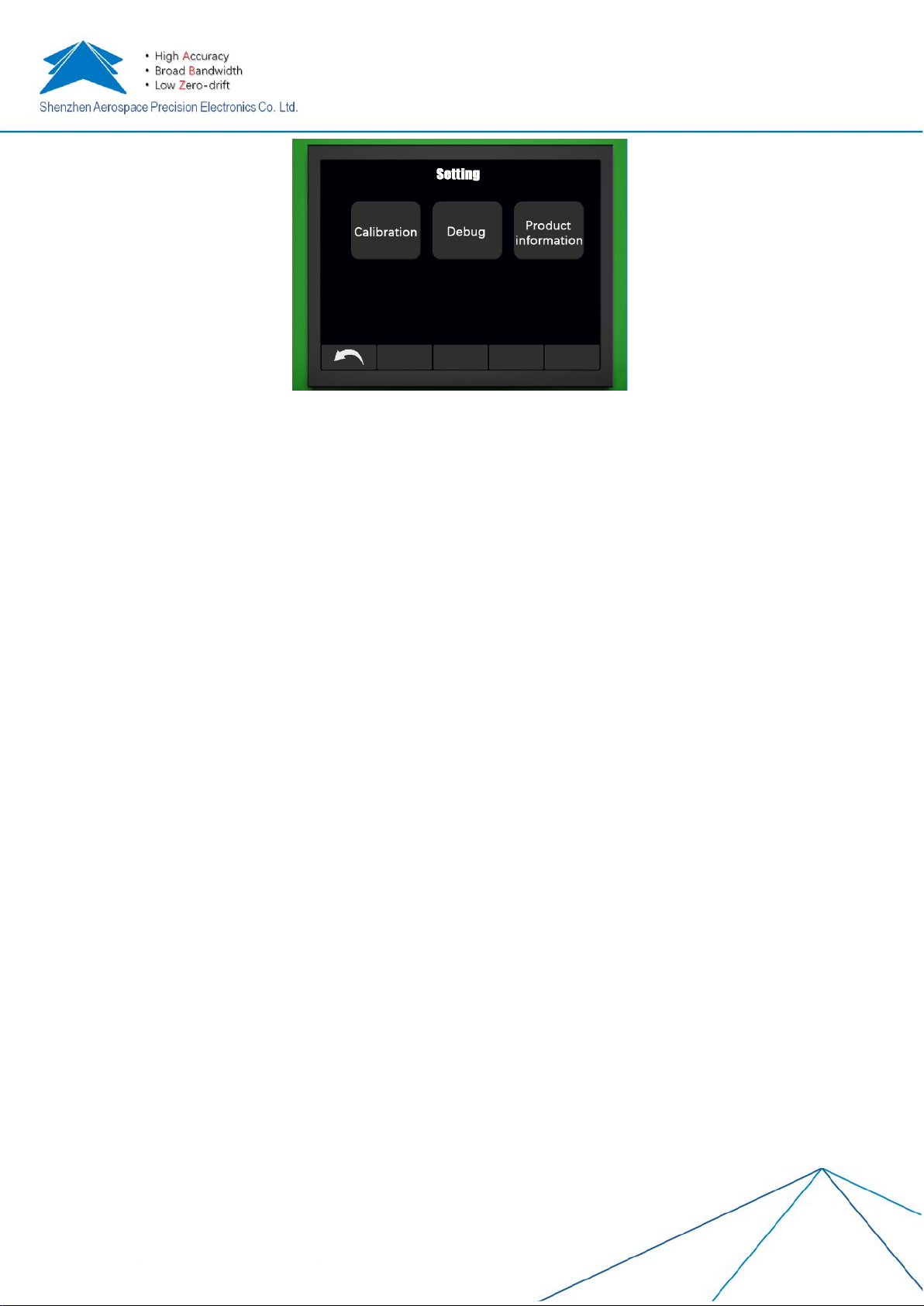
After clicking "Settings" on the main interface, this instrument will enter the setting interface
as shown below, and you can click “Calibration”button to view information such as the
product software version.
20
4.3The usage of extension ring
1) When measuring current is in a small range, please use the corresponding extension
ring to connect it to the threading hole of the instrument.
2) Before measuring, let the extension ring pass through the test hole of the instrument
according to the direction of the mark, and then insert the joint. The red terminal is
connected to the inflow current, and the black terminal is connected to the outflow
current.
3) Connect the X10 top ring (optional), turn on the power switch, then enter the main
interface, and click “AC” or “DC”. After entering the AC or DC measurement interface,
click “Current X10”.
Precautions
1) In the "current X10" mode, the optional corresponding extension ring must be selected.
2) The current direction marked on the extension ring should be the same as the current
direction marked on the meter case. If the directions are inconsistent, the measured
value is negative when measuring the forward DC current. When measuring AC
voltage and current, the phase of the AC voltage and AC current signal is 180 degrees
out of the true phase. The negative AC current measurement is not affected only when
the AC current is measured and the directions are inconsistent.
3) The connection of the extension ring must be tight to prevent from breaking. After the
extension ring is inserted, the impedance of the two terminals can be measured with a
multimeter. When the link is correct, the impedance between the two terminals is about
zero.
4) The extension ring must pass through the test hole of the instrument completely. If the
current line is worn less or more, the measurement error will occur. If the "current X10"
extension ring is used, the number of turns passing through the meter hole should be
10. If the number of turns is incorrect, there will be an error in the measurement.
Other manuals for HIU Series
1
Table of contents
Other Hangzhi Measuring Instrument manuals


