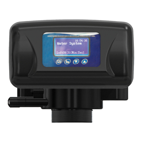
Hankscraft Runxin HS Series User manual

Innovative Solutions for Your Water
HS / HL Valves & Systems
Service Manual
Hankscraft Runxin, LLC
300 Wengel Drive
Reedsburg, WI 53959
608.524.9465
hrh2o.co

HS / HL Valves & Systems Service Manual
Hankscraft Runxin, LLC 300 Wengel rive 608.524.9465 hrh2o.com sales@hrh2o.com
2
Table of Contents
1. Introduction .................................................................................................................................................... 3
2. System Specifications Form for Record Keeping .............................................................................................. 4
3. Pre-Installation Checklist ............................................................................................................................. 5-6
4. System Installation .................................................................................................................................... 7-16
a. Product Di ensions, Rough-Ins, Unit Location, Plu bing & Mechanical Setup .................................. 7-8
b. Control Valve Installation, Syste Sizing Chart, Bypass Installation ................................................... 9-10
c. Plu bing Connections, Drain Line Installation ...................................................................................... 11
d. Brine Line Installation, Brine Tank Installation .................................................................................. 12-15
e. Syste Installation Chart ....................................................................................................................... 16
5. Valve Start-up Procedure ......................................................................................................................... 17-24
a. HS-STC / HL-STC Ti er Valve Start-Up Procedure ............................................................................ 17-18
b. HS-FTC / HL-FTC Filter Ti er Valve Start-Up Procedure ................................................................... 19-20
c. HS-SMM / HL-SMM Meter Valve Start-Up Procedure ...................................................................... 21-24
6. Sanitizing Procedure ..................................................................................................................................... 25
7. Water Flow iagrams............................................................................................................................... 26-28
8. Assembly rawing and Parts List ............................................................................................................. 29-44
a. HS-STC, HS-FTC, HS- SMM / HL-STC, HL-FTC, HL-SMM Valve Asse bly and Parts List ..................... 29-40
b. HS / HL Valve Body Asse bly and Parts List ..................................................................................... 41-42
c. HS-SMM / HL-SMM Meter Asse bly and Parts List .............................................................................. 43
d. Stainless Steel Bypass ............................................................................................................................. 44
9. Service Instructions .................................................................................................................................. 45-53
a. Replacing Brine Valve, Injectors, and Screen .................................................................................... 45-46
b. Replacing Ti er ................................................................................................................................. 46-47
c. Replacing Piston Asse bly ................................................................................................................ 48-49
d. Replacing Seals and Spacers .............................................................................................................. 49-50
e. Replacing Meter ................................................................................................................................ 51-52
f. Replacing Meter Cover and I peller ................................................................................................ 52-53
10. Troubleshooting ....................................................................................................................................... 54-55
a. Softener Syste s .................................................................................................................................... 54
b. Filter Syste s ......................................................................................................................................... 55
11. Hankscraft Runxin Warranty Statement .................................................................................................. 56-57
12. Contact Information...................................................................................................................................... 58

HS / HL Valves & Systems Service Manual
Hankscraft Runxin, LLC 300 Wengel rive 608.524.9465 hrh2o.com sales@hrh2o.com
3
1. Introduction
Thank you for choosing a Hankscraft Runxin HS / HL Mechanical Valve. HS and HL control valves take
the ti eless design of industry standard piston valves and updates the to exceed odern
perfor ance de ands. Their durable, high-perfor ance construction has down-flow regeneration,
industry co patible pistons, injectors and seal/spacers, and an L bracket design for hassle-free
operation and aintenance.
These valves utilize high efficiency that lowers annual power use and can be configured with optional
24V otors and extended eters. HS and HL valves also feature a quick-connect drain with optional
offset, increasing flexibility for installs.
Hankscraft Runxin’s echanical control valves are anufactured using i proved aterials and process
and are put through a rigid, 100% quality inspection before they leave the factory. Our products will
give you peace of ind that will result in fewer warranty callbacks, provide a better product to your
custo ers, and put ore oney in your pocket.
HS / HL Valves Feature:
• I proved anufacturing and durability, lower power usage
• 24V otor and extended eter options
• Quick-connect drain with optional offset

HS / HL Valves & Systems Service Manual
Hankscraft Runxin, LLC 300 Wengel rive 608.524.9465 hrh2o.com sales@hrh2o.com
4
2. System Specifications Form for Record Keeping
Installer
Na e: _______________________________________________________________________________
Address: ___________________________________________________ City/State: _________________
Phone: ____________________________________________________ Install Date: ________________
Softener System Configuration
Tank Size: Dia. _______in. Height _______in. Resin Volu e: ________cu/ft.
Brine Tank Capacity: 85L 100L 130L
Media: ______________________________________________________________________________
Control Valve Serial Nu ber (label located on valve body front): ________________________________
Valve Style:
HS-FTC HS-STC HS-SMM HL-STC HL-SMM HL-SMM-24 HL-SMM-24-EXT
Day/Ti e of Regeneration: ______________________________________________________________
Drain Line Flow Control (DLFC): __________ gp Brine Line Flow Control (BLFC): __________ gp
Injector Size: ____________________________________ Salt Setting: __________________________
Meter Gallon Setting: _____________________________ gallons
Water Conditions and Quality
Total Hardness: _______ grains Iron (Fe): _______ pp Acid (pH): _______ TDS: _______ pp
Pressure of Inlet Water: _________ psi Other: ____________________________________________
Water Source: Well Water City Water Other: ________________________

HS / HL Valves & Systems Service Manual
Hankscraft Runxin, LLC 300 Wengel rive 608.524.9465 hrh2o.com sales@hrh2o.com
5
3. Pre-Installation Checklist
IMPORTANT NOTICE
Read through the instructions thoroughly and obtain all aterials and tools before proceeding with the
installation. Be sure to follow all applicable national, state, county, and local plu bing codes and
regulations.
All plu bing and electrical work should be perfor ed by an accredited professional to ensure all local,
state, and unicipal guidelines are et.
During cold weather it is reco ended that the installer war the valve to roo te perature before
operating.
Required Operating Conditions
Working Conditions
Working Pressure 25psi
~
120psi
Water Te perature 40 °F
~
100 °F
Working Environment
Environ ent Te perature 40 °F
~
100 °F
Relative Hu idity ≤95%
Power Source AC100
~
240V / 50
~
60Hz
CAUTION
Do not exceed 120 psi water pressure.
Do not exceed 40° C / 100° F water te perature.
Do not subject unit to freezing conditions.
Failure to use this product within the described conditions ay void the warranty.

HS / HL Valves & Systems Service Manual
Hankscraft Runxin, LLC 300 Wengel rive 608.524.9465 hrh2o.com sales@hrh2o.com
6
•All plu bing and electrical work should be perfor ed by an accredited professional to ensure all
local, state, and unicipal guidelines are et.
•An uninterrupted alternating current (A/C) supply is required. Please ake sure voltage supply is
co patible with unit before installation.
•Conditions of existing plu bing should not be clogged with li e or iron build-up. Replace piping
that has heavy li e and/or iron build-up. If there is an iron concern, install an iron filter unit
ahead of the water softener. Plu bing that has heavy li e and iron buildup inhibits the
operation of softening syste .
•When there is oderate to high turbidity, a filter should be installed on the inlet before the
water softening syste .
•If the water pressure exceeds 120psi, a pressure reducing valve ust be installed before the
water inlet. If the water pressure exceeds 80 psi, installing a pressure reducing valve before the
water inlet is highly reco ended. If the water pressure is under 25psi, a booster pu p ust
be installed before the water inlet.
•Ensure there is salt in the brine tank at all ti es when this valve is used for softening. The brine
tank should contain clean water and softening salt only, at least 99.5% pure. Do not use s all
grain salt.
•Always install a bypass valve.
•Replace ent parts for the valve should only be purchased through Hankscraft Runxin resellers.
•Regular interval onitoring of the water quality and work environ ent is reco ended to
insure proper operation of the valve and syste .

HS / HL Valves & Systems Service Manual
Hankscraft Runxin, LLC 300 Wengel rive 608.524.9465 hrh2o.com sales@hrh2o.com
7
4. System Installation
Product imensions – HS / HL Control Valves
Length (max.) Width (max.) Height (max.) Regeneration Mode
7.5" 4" 7.5" Down-flow
Inlet Port Outlet Port rain Port Brine Port Base Riser Pipe
3/4" 3/4" 1/2" NPTF 3/8" 2.5"NPSM 1.05"
The
se
valve dimensions are for reference only.
Plumbing Rough-Ins – HS / HL Control Valves
Bypass
Tank
Center to
End of
Bypass
Inlet/
Outlet
Center
Inlet/
Outlet
Height
9x48 Tank
Inlet/
Outlet
Height
10x44 Tank
Inlet/
Outlet
Height
10x54 Tank
Inlet/
Outlet
Height
12x52 Tank
Inlet/
Outlet
Height
13x54 Tank
1" Metal Bypass 5-3/8" 2" 50" 46-5/8" 56-3/4" 54-7/8" 56-7/8"
3/4" Metal Bypass 5-1/4" 2" 50" 46-5/8" 56-3/4" 54-7/8" 56-7/8"
The
se
valve
dimensions are for reference only.
Unit Location
•Locate the filter or softener close to a clean working floor drain away fro direct sunlight and any
heat sources. This will ini ize consu er i pact in the event of alfunction.
•Ensure the unit is installed with enough space for operation and aintenance.
•The installation surface should be clean, level and stable for both the pressure tank and brine tank.

HS / HL Valves & Systems Service Manual
Hankscraft Runxin, LLC 300 Wengel rive 608.524.9465 hrh2o.com sales@hrh2o.com
8
Plumbing and Mechanical Setup
•Co plete all plu bing according to local, state, and federal plu bing codes.
oA 1/2" (13 ) ini u drain pipe should be used. However, if the backwash flow rates
exceed 7gp or the length exceeds 20 feet (6 ) then a 3/4" (19 ) drain pipe should
be used.
oThere ust be an air gap between the drain line and the drain to prevent siphoning of
conta inated water back into the resin tank.
•Use only Teflon tape on the drain fitting.
•Solder joints should be co pleted prior to connecting piping to the valve. Solder joints near the
drain ust be done before connecting the Drain Line Flow Control fitting (DLFC). Leave at least 6"
(152 ) between the DLFC and solder joints when soldering pipes that are connected on the
DLFC. Failure to do this could cause interior da age to valve. The valve anufacturer is not
responsible for da age incurred during installation.
•When turning threaded pipe fittings onto plastic fitting, take precaution not to cross thread or over
tighten.
•Ensure the unit is installed with enough space for operation and aintenance.

HS / HL Valves & Systems Service Manual
Hankscraft Runxin, LLC 300 Wengel rive 608.524.9465 hrh2o.com sales@hrh2o.com
9
Control Valve Installation
1. Cut the 1" (25 ) distributor tube (1.05" O.D.) flush with the top of the tank. Take care to keep
foreign aterial out of ineral tank. If purchased as a co plete syste , the tube has already been
cut and installed.
2. Insert distributor tube with lower basket into the center of the
pressure tank.
3. Plug the riser pipe and fill the pressure tank with resin. If purchased as a
co plete syste fro Hankscraft Runxin the edia has been installed.
Media quantity is relative to desired capacity and tank size.
4. Lubricate the valve center hub O-ring with silicone lubricant only.
5. Install the upper basket with a twist and lock action to center hub of
the valve.
6. Lubricate, with silicone lubricant, and install the valve base O-ring around
the neck of the valve.
7. Place valve on tank with the distributor tube inserted down the iddle of
the upper basket. Twist the valve on to the tank to secure valve to the tank.
System Sizing Chart
Tank Size Injector Slow Rinse
@ 40 psi
Brine raw
@ 40 psi
¹
BLFC
²
LFC
9" #1 White .45 gp .28 gp .25 gp 2.0 gp
10" #1 White .45 gp .38 gp .5 gp 2.4 gp
12" #2 Blue .84 gp .56 gp 1.0 gp 3.5 gp
13" #2 Blue .84 gp .56 gp 1.0 gp 4.0 gp
14" #4 Green 1.0 gp .63 gp 1.0 gp 5.0 gp
16" #4 Green 1.0 gp .63 gp 1.0 gp 7.0 gp
Due to varying water conditions, tank sizes, and water pressures, use the above as guidelines only.
¹BLF (Brine Line Flow ontrol), refill rate for filling brine tank.
²DLF (Drain Line Flow ontrol), backwash and rapid rinse flow rates.

HS / HL Valves & Systems Service Manual
Hankscraft Runxin, LLC 300 Wengel rive 608.524.9465 hrh2o.com sales@hrh2o.com
10
Bypass Installation
Stainless Steel Bypass – 1606K/1606KB
1. Grease bypass O-rings and press onto valve.
2. Secure with clips.
Before running the valve for the first ti e,
flush out the water line and bypass:
3. Be sure the bypass is closed.
4. Turn the water source on at the inlet to the house.
5. Disconnect the bypass fro the valve.
6. Put a container under the bypass. Open the bypass to re ove any foreign aterial out of the
water lines.
7. Close the bypass.
8. Re-connect the bypass to the valve.
9. Open the bypass slowly, to avoid water ha ering.
10. Let water flow into the pressure tank. When water flow stops, slowly open a cold water tap
nearby and let water run until it runs clear and air is purged fro the unit. Then close tap.
11. Check for and repair any leaks.
12. Start-up procedures are shown on the following pages for each different valve type. Locate your
valve type and follow the start-up procedures listed.

HS / HL Valves & Systems Service Manual
Hankscraft Runxin, LLC 300 Wengel rive 608.524.9465 hrh2o.com sales@hrh2o.com
11
Plumbing Connections Installation
1. Connect inlet pipe with inlet connector of bypass.
2. Connect outlet pipe with outlet connector of bypass.
3. See Fig. 1
rain Line Installation
1. Install drain line with an air gap to the floor drain.
(Valve drain hose not supplied)
2. See Fig. 2
Fig. 1
Fig. 2
CAUTION
An air gap is required between the drain line
and the drain (sewer). This avoids a syphon
effect and reverse conta ination.

HS / HL Valves & Systems Service Manual
Hankscraft Runxin, LLC 300 Wengel rive 608.524.9465 hrh2o.com sales@hrh2o.com
12
Brine Line Installation
1. Slide brine nut and Ferrule (with the tapered end
facing the inside of the brine nut) onto the 3/8"
brine tubing.
2. Install the filter screen into the tube insert and press
both into the end of brine tube.
3. Insert tube into brine connector and secure brine
nut to the brine connector.
4. See Fig. 3
Brine Tank Installation
1. Unpack brine tank co ponents
•Brine tank standoff with nut and washer
•Overflow elbow with nut and washer
•Optional quick connect clips
2. Open brine well and re ove float. Ensure the
inside of the tank and brine well are free of debris.
Fig. 3

HS / HL Valves & Systems Service Manual
Hankscraft Runxin, LLC 300 Wengel rive 608.524.9465 hrh2o.com sales@hrh2o.com
13
3. Asse ble salt grid (4 feet, 1 base). Feet clip into the botto of the base.
4. Insert asse bled salt grid into brine tank by lining up the cut out hole with the
drilled holes on the brine tank.
5. Hold float and connected ABS tubing (at the botto ; securing the ABS
tubing), turn the black nut counterclockwise while the tubing is secured
in place. Set to desired salt setting and retighten float nut.
Tank Size
Letter
Salt Level (See Fig. 4) Salt Setting
9x48
To white tape or above 9 lbs.
10x44
Halfway between white/blue tape or above ~ 10.5 lbs.
10x54
To blue tape or above 12 lbs.
12x52
To green tape or above 15 lbs.
13x54
To green tape or above > 15 lbs.
A
B
A
B
C
E
E
C

HS / HL Valves & Systems Service Manual
Hankscraft Runxin, LLC 300 Wengel rive 608.524.9465 hrh2o.com sales@hrh2o.com
14
6. Insert the brine well, aking sure the botto brine well cap is attached. Insert
the float asse bly by lining up the top cut out holes.
Through testing there have been so e instances where the botto float
asse bly cap can co e off of the tube when force is applied. Therefore we
strongly suggest using Gorilla Glue or any equivalent glue to glue the botto
(only) float asse bly cap to the tube to prevent this cap fro co ing off the
tube.
7. Install brine tank standoff over the float asse bly and insert into top cut
out hole. Attach washer on outside of tank and secure unit.
8. Insert brine line into the top cut out hole, through the standoff, and
into the quick connect elbow (optional: attach blue clips). Press fir ly
to ake sure brine line is fully inserted into the quick connect.

HS / HL Valves & Systems Service Manual
Hankscraft Runxin, LLC 300 Wengel rive 608.524.9465 hrh2o.com sales@hrh2o.com
15
9. Install overflow elbow fitting with washer on the outside of tank. Fasten
nut on the inside of the tank.
10. Replace brine well lid.
11. Replace brine tank lid.

HS / HL Valves & Systems Service Manual
Hankscraft Runxin, LLC 300 Wengel rive 608.524.9465 hrh2o.com sales@hrh2o.com
16
System Installation Chart

HS / HL Valves & Systems Service Manual
Hankscraft Runxin, LLC 300 Wengel rive 608.524.9465 hrh2o.com sales@hrh2o.com
17
5. Valve Start-Up Procedures
HS-STC / HL-STC Timer Control Valve Start-Up Procedure
1. Make sure the bypass valve is in the service position. Manually index the valve to the Service
position and allow water to flow into the resin tank (pressure tank). When the water flow stops,
open a softened water tap until all air is released fro the lines. Close tap.
Regeneration cycles ay be dialed anually by turning the knob clockwise until the desired
cycle appears.
2. Manually index the valve to Backwash position; allow water to flow out the drain for 3 to 4
inutes for color throw.
3. Re ove back cover plate. Make sure the salt wheel is set to desired dosage.
4. Manually index the control to the Brine Refill position and allow the brine tank to fill to the top of
the air check.
5. Manually index the valve to the Brine Draw position, allow the valve to draw water fro the
brine tank until it stops.
6. Plug the valve into an approved power source. Preferably a GFI grounded outlet. Look in the sight
hole in the back of the otor to see that it is running.

HS / HL Valves & Systems Service Manual
Hankscraft Runxin, LLC 300 Wengel rive 608.524.9465 hrh2o.com sales@hrh2o.com
18
7. Set the days that regeneration is to occur by sliding tabs on Skipper Wheel outward. Each tab is
one day. Move clockwise fro indicator to obtain the desired regeneration schedule. The tab at
the red indicator is tonight.
8. Manually advance the valve to the beginning of the Brine Refill position and allow the valve to
return to the In Service position auto atically. This will fill the brine tank with the correct
a ount of water.
9. Now add salt to the brine tank. (40 lbs. ini u , 120 lbs. axi u )
We reco end using pellet salt, NOT solar or rock salt. Install brine tank cover.
10. Replace back cover plate on the valve. Be sure cable is not pinched between cover and housing.
11. Turn a faucet on, away fro the installation location, until the water fro the plu bing lines has
been purged.
12. Softening syste is now fully operational.
13. Take a water sa ple to verify and test for hardness reduction.
Hardness
PPM
(GPG)
17-85
(1-5)
86-170
(6-10)
171-
256
(11-15)
257-
342
(16-20)
343-
427
(21-25)
428-513
(26-30)
514-
598
(31-35)
599-684
(36-40)
685-769
(41-45)
770-855
(46-50)
856-940
(51-55)
941-
1026
(56-60)
1027-
1111
(61-65)
1112-
1197
(66-70)
1198-
1282
(71-75)
1283-
1368
(76-80)
No. Of
People Softeners - Calendar Clock Regeneration Frequency – Number Of Tab Pulls
2 1 1 1 1 1 2 2 2 2 2 3 3 3 3 3 3
3 1 1 2 2 3 3 3 3 3 3 4 4 4 4 4 4
4 1 2 2 2 3 3 3 4 4 4 6 6 6 6 6 6
5 2 2 3 3 4 4 4 4 6 6 6 6 12 12 12 12
6 2 2 3 3 4 4 4 6 6 12 12 12 12 12 12 12
7 2 3 3 4 4 6 6 6 12 12 12 12 12 12 12 12
8 2 3 3 4 6 6 6 6 12 12 12 12 12 12 12 12
9 3 3 4 4 6 6 12 12 12 12 12 12 12 12 12 12
10 3 4 4 6 6 12 12 12 12 12 12 12 12 12 12 12

HS / HL Valves & Systems Service Manual
Hankscraft Runxin, LLC 300 Wengel rive 608.524.9465 hrh2o.com sales@hrh2o.com
19
HS-FTC / HL-FTC Timer Control Valve Start-Up Procedure
1. Manually index the valve to the Service position and allow water to flow into the resin tank
(pressure tank). When the water flow stops, open a water tap until all air is released fro the
lines. Close tap.
Regeneration cycles ay be dialed anually by turning the knob clockwise until the desired
cycle appears.
2. Manually index the valve to Backwash position; allow water to flow out the drain for 3 to 4
inutes for color throw.
3. Plug the valve into an approved power source. Preferably a GFI grounded outlet. Look in the sight
hole in the back of the otor to see that it is running.
4. Set the days that regeneration is to occur by sliding tabs on the Skipper Wheel outward. Each tab
equals one day. Move clockwise fro indicator to obtain the desired regeneration schedule. The
tab at the red indicator is tonight.
5. Turn a faucet on, away fro the installation location, until the water fro the plu bing lines has
been purged.
6. Filtering syste is now fully operational.

HS / HL Valves & Systems Service Manual
Hankscraft Runxin, LLC 300 Wengel rive 608.524.9465 hrh2o.com sales@hrh2o.com
20
Sand
Filter Sediment Turbidity Mild Average Extreme
Carbon
Filters Taste and Odor Mild Average Extreme
Iron
Filters
PPM Ironx1
PPM Manganesex1
PPM Sulfurx1
.5 1 1.5 2 2.5 3 3.5 4 4.5 5 5.5 6 6.5 7 7.5 8
No. Of People Softeners - Calendar Clock Regeneration Frequency – Number Of Tab Pulls
2 1 1 1 1 1 2 2 2 2 2 3 3 3 3 3 3
3 1 1 2 2 3 3 3 3 3 3 4 4 4 4 4 4
4 1 2 2 2 3 3 3 4 4 4 6 6 6 6 6 6
5 2 2 3 3 4 4 4 4 6 6 6 6 12 12 12 12
6 2 2 3 3 4 4 4 6 6 12 12 12 12 12 12 12
7 2 3 3 4 4 6 6 6 12 12 12 12 12 12 12 12
8 2 3 3 4 6 6 6 6 12 12 12 12 12 12 12 12
9 3 3 4 4 6 6 12 12 12 12 12 12 12 12 12 12
10 3 4 4 6 6 12 12 12 12 12 12 12 12 12 12 12
This manual suits for next models
8
Table of contents
Other Hankscraft Runxin Control Unit manuals
Popular Control Unit manuals by other brands

elsner elektronik
elsner elektronik KNX A3-B2 Installation and adjustment
Pentair
Pentair F251 Installation & maintenance instructions
M-system
M-system M6NPS1 instruction manual

Siemens
Siemens SINAMICS RAILCTRL Function manual
Dixon
Dixon 3030SQ Installation & operating instructions

Aulisa
Aulisa Guardian Angel Rx Instructions for use
