manuals.online logo
Brands
  1. Home
  2. •
  3. Brands
  4. •
  5. Bosch
  6. •
  7. Control Unit
  8. •
  9. Bosch ICP-COM-IF User manual

Bosch ICP-COM-IF User manual

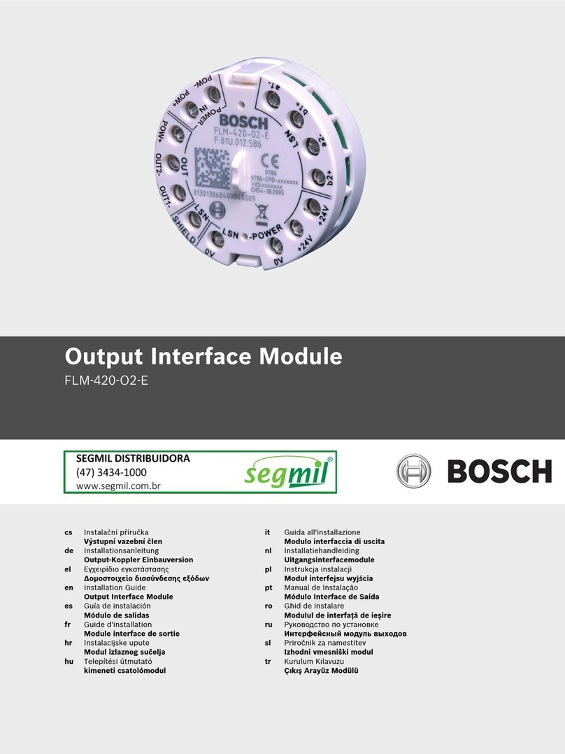
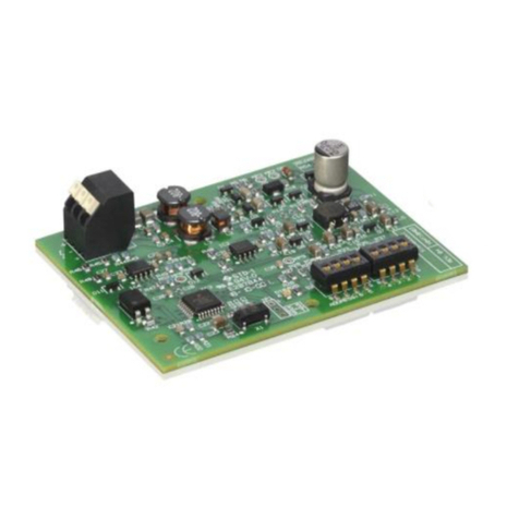
Description of the ICP-COM-IF Module
The ICP-COM-
IF Module allows an isolated connection to be created between the MAP5000 (Interface
Module DE) and an external communicator (for example the AT 2000) via the parallel S1 interface. The
ICP-COM-IF Module offers:
Notes for installation
-The ICP-COM-IF Module can be mounted on the hinged mounting plate or the mounting rails of the
MAP control panel housing.
-A clearance of 15 mm is required on either side for subsequent wiring. Pull to disconnect the
connectors.
-The enclosure of an external transmission unit has to be mounted side by side to the panel enclosure
where the ICP-COM-IF module is mounted.
Mounting
1. Hook the ICP-COM-IF Module carrier plate into the existing breadboard of the
hinged mounting
plate or onto the mounting rails.
2. Use the screw provided to secure the carrier plate to the bottom rail.
•Seven outputs:
The output signals from the MAP Interface Module DE
control the ICP-COM-IF Module relays that provide isolated
changeover contacts (R1 to R7)
•Two inputs:
The inputs ST and R (for the "Communicator fault" or
"Negative confirmation" signals, for instance) can be
controlled via the following:
- isolated contacts
- C points (isolated via optocouplers)
Technical specifications
Rated voltage +10 to +28 V DC
Rated current
67 mA at 28 V or 180 mA at 10 V
Relay contacts rating 3 A/120 V AC, 3 A/28 V DC
Temperature range −25 °C to +55 °C
Weight 198 g
Dimensions (L x W x H) 132 mm x 85 mm x 20 mm (5.2 inches x 3.3
inches x 0.8 inches)
Bosch Sicherheitssysteme GmbH
Robert
-Bosch-Ring 5
85630 Grasbrunn
Germany
www.boschsecurity.com
© Bosch Sicherheitssysteme GmbH, 2014
V
32014/11
1
ICP-COM-IF
EN
Installation guide
VdS class C G 111040
EN 50131
-2-6 Grade 3
Jumper settings
The inputs ST and R can be controlled via the following:
•isolated contacts
•C points (isolated via optocouplers)
To control the inputs via external "isolated contacts" or "C points", the jumpers must be
connected as follows:
Input Jumper setting Description
ST Control via isolated contact (factory default)
R Control via isolated contact (factory default)
ST Control via C point
R Control via C point
3
1
J1
ST
2
3
1
J2
ST
2
3
1
J3
R
2
3
1
J4
R
2
1
J1
ST
2
3
1
J2
ST
2
3
1
J3
R
2
3
1
J4
R
2
3
Relays
Output/input
Stand-by mode
Activation with
R1
Output for the communicator alarm line ML1
On
Summary alarm
R2
Output for the communicator alarm line ML2
Off
Duress
R3
Output for the communicator alarm line ML3
Off
Holdup
R4
Output for the communicator alarm line ML4
On
Intrusion/Tamper
R5
Output for the communicator alarm line ML5
On
Summary Trouble
R6
Output for the communicator alarm line ML6
Off
Fire
R7
Output for the communicator alarm line ML7
Off
Armed (any area)
ST
Input from external communicator
Communicator fault
R
Input from external communicator
Negative confirmation
© Bosch Sicherheit
ssysteme GmbH, 2014
V
32014/11
2
A
B
Relay 1
AT 2000
A
B
A
B
A
B
A
B
A
B
A
B
Relay 2
Remote communicator, for example the AT 2000
R1A
R1B
R1C
C1C
ML7
ML6
ML5
ML4
ML3
ML2
ML1
AT 2000 programming
•
Relay 1: "Continuous activation", stand-by "on"
•
Relay 2: "5 seconds", stand-by "off"
•
ML1–ML7: Conventional Lines Intrusion
Relay 2:
Negative
confirmation
Relay 1:
Communicator fault
C1B
C1A
ICP
-COM-IF
MAP Interface Module DE
The ribbon cable is
a
ttached to the MAP
Inter
face Module DE
Parallel S1 in-
terface
Red
marking at
top
1.
The size of the terminal resistors (RE) to be looped in
depends on the communicator (for example 10 k for the AT 2000).
2.
Pull to disconnect the connectors.
ML2
ML3
ML4
ML6
ML5
Red
m
arking
at top

Other Bosch Control Unit manuals

Bosch Rexroth IMpnio User manual

Bosch

Bosch Rexroth IMpnio User manual

Bosch KTS 5 Series User manual

Bosch

Bosch KTS 5 Series User manual

Bosch B901 User manual

Bosch

Bosch B901 User manual

Bosch MM100 Service manual

Bosch

Bosch MM100 Service manual

Bosch Rexroth VKK User manual

Bosch

Bosch Rexroth VKK User manual

Bosch DCU 220 Setup guide

Bosch

Bosch DCU 220 Setup guide

Bosch Rexroth M SED 6 VE1 Series User manual

Bosch

Bosch Rexroth M SED 6 VE1 Series User manual

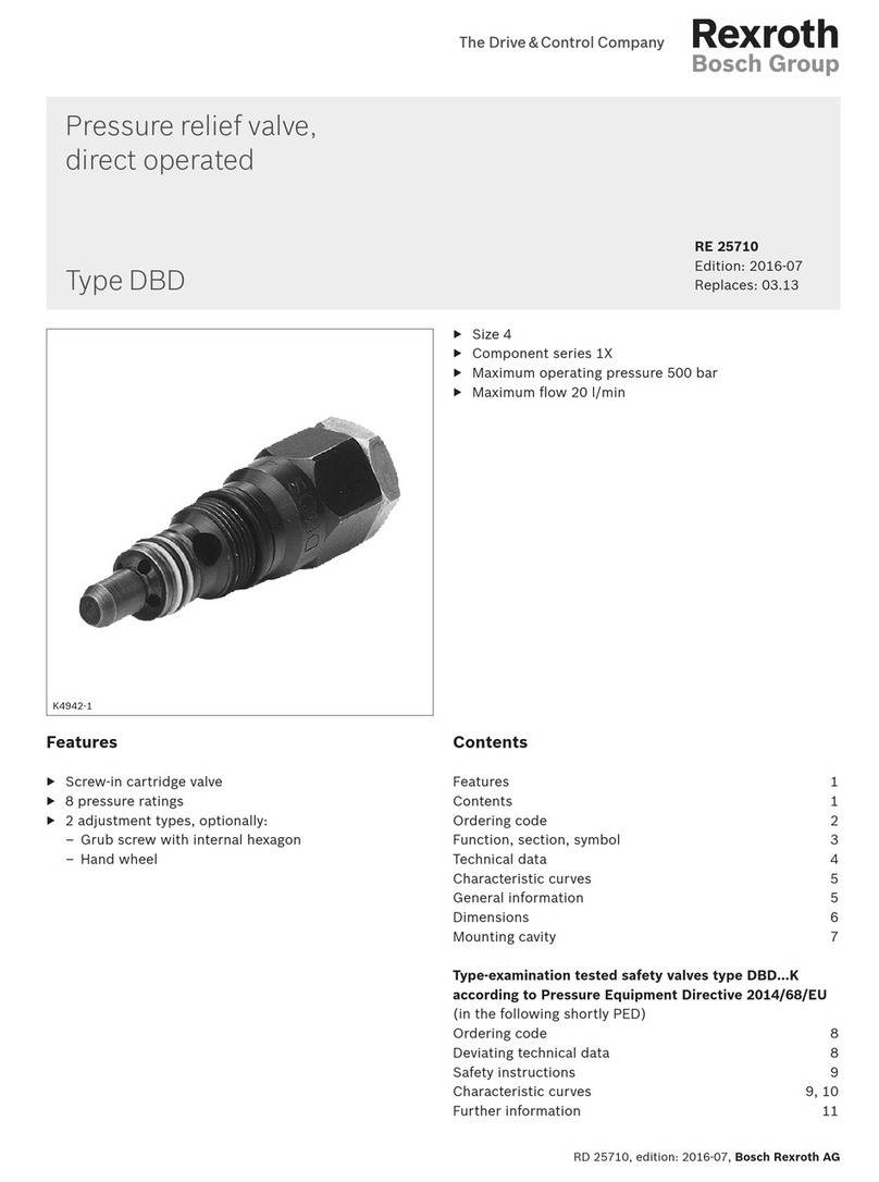
Bosch REXROTH DBD User manual

Bosch

Bosch REXROTH DBD User manual

Bosch Rexroth IndraControl VAC 31 User manual

Bosch

Bosch Rexroth IndraControl VAC 31 User manual

Bosch Rexroth IndraDrive CSB02 Technical manual

Bosch

Bosch Rexroth IndraDrive CSB02 Technical manual

Bosch ConnectModule BCM3100 User manual

Bosch

Bosch ConnectModule BCM3100 User manual

Bosch Rexroth BTV 16 Technical manual

Bosch

Bosch Rexroth BTV 16 Technical manual

Bosch VCU User manual

Bosch

Bosch VCU User manual

Bosch KTS Truck User manual

Bosch

Bosch KTS Truck User manual

Bosch ConnectModule BCM3100 User manual

Bosch

Bosch ConnectModule BCM3100 User manual

Bosch FLM-I 420-S User manual

Bosch

Bosch FLM-I 420-S User manual

Bosch DCU 220 Setup guide

Bosch

Bosch DCU 220 Setup guide

Bosch Rexroth 2THE5R User manual

Bosch

Bosch Rexroth 2THE5R User manual

Bosch D113 User manual

Bosch

Bosch D113 User manual
Bosch PAVIRO PVA-1WEOL Installation and operation manual
Bosch

Bosch PAVIRO PVA-1WEOL Installation and operation manual

Bosch Professional GCY 42 User manual

Bosch

Bosch Professional GCY 42 User manual

Bosch CFB 840 User guide

Bosch

Bosch CFB 840 User guide

Bosch TouchOne User manual

Bosch

Bosch TouchOne User manual

Bosch C-IR 20 User manual

Bosch

Bosch C-IR 20 User manual

Popular Control Unit manuals by other brands

Keysight N2125A user guide

Keysight

Keysight N2125A user guide

System Sensor M500SAP Installation and maintenance instructions

System Sensor

System Sensor M500SAP Installation and maintenance instructions

Siemens 3VL92 Series operating instructions

Siemens

Siemens 3VL92 Series operating instructions

Nibco T-413-B Installation and maintenance guide

Nibco

Nibco T-413-B Installation and maintenance guide

Kilowatt Labs SIRIUS 5000-384-A-1C-TM-SD-A-X-X-G user manual

Kilowatt Labs

Kilowatt Labs SIRIUS 5000-384-A-1C-TM-SD-A-X-X-G user manual

PRASTEL UNIK1E Technical Manual for the Installer

PRASTEL

PRASTEL UNIK1E Technical Manual for the Installer

Kutai electronics EC-05 Operation manual

Kutai electronics

Kutai electronics EC-05 Operation manual

DH Instruments PK-7600-VAC-VENT installation instructions

DH Instruments

DH Instruments PK-7600-VAC-VENT installation instructions

SMC Networks VV100 Series Installation and maintenance manual

SMC Networks

SMC Networks VV100 Series Installation and maintenance manual

SCHUNK SDV-P Assembly and operating manual

SCHUNK

SCHUNK SDV-P Assembly and operating manual

WAGO 750-508/040-000 manual

WAGO

WAGO 750-508/040-000 manual

KSB LevelControl Basic 2 Supplementary Operating Manual

KSB

KSB LevelControl Basic 2 Supplementary Operating Manual

GEM eSyLite 629 operating instructions

GEM

GEM eSyLite 629 operating instructions

schmersal PSCBR-C-100 Series installation manual

schmersal

schmersal PSCBR-C-100 Series installation manual

ACS ACM1281U-C7 Reference manual

ACS

ACS ACM1281U-C7 Reference manual

SEW-Eurodrive MOVIAXIS MXR manual

SEW-Eurodrive

SEW-Eurodrive MOVIAXIS MXR manual

Cherry AFZE quick start guide

Cherry

Cherry AFZE quick start guide

Bardiani Valvole B925 Use and maintenance manual

Bardiani Valvole

Bardiani Valvole B925 Use and maintenance manual

manuals.online logo
manuals.online logoBrands
  • About & Mission
  • Contact us
  • Privacy Policy
  • Terms and Conditions

Copyright 2025 Manuals.Online. All Rights Reserved.