HANMEY AM60 User manual

1
Operate & Parts Manual
Hedge cutter AM60/AM80/AM100

2
LIST OF CONTENTS
SAFETY PRECAUTIONS Page 5
FITTING Page 9
INITIAL ATTACHMENT TO TRACTOR Page 12
FLAILHEAD ATTACHMENT Page 24
REMOVAL FROM TRACTOR Page 25
STORAGE Page 26
OPERATION Page 27
OPERATION GUARD Page 28
MACHINE CONTROLS Page 28
BREAKAWAY Page 29
MOVING INTO THE TRANSPORT POSITION Page 31
MOVING FROM TRANSPORT TO WORK Page 32
ROTOR OPERATING SPEED Page 33
HIGH VOLTAGE CABLES Page 34
OVERHEAD OBSTRUCTIONS Page 34
WORKING ON ADVERSE SLOPES Page 36
MAINTENANCE Page 36
LUBRICATION
General Page 36
P.T.O. shaft Page 37
HYDRAULIC SYSTEM Page 38
HYDRAULIC HOSES Page 39
PARTS LIST Page 40

3
READ THE BOOK FIRST
It might save hours and pounds later !
When ordering spare parts always quote
The Machine Type
The Machine Serial Number
The Part Number
Factory re-built service exchange units of the major
hydraulic components are available from your Dealer

4
NOISE
The equivalent daily personal noise exposure from this machine, measured at the
operators’ ear, is within the range 78 – 85 DB. These figures apply to a normal distribution
of use where the noise fluctuates between zero and maximum. The figures assume that
the machine is fitted to a tractor with a quiet cab with the windows closed in a generally
open environment. We recommend that the windows are kept closed. With the cab rear
window open the equivalent daily personal noise exposure will increase to a figure within
the range 82 –88 DB. At equivalent daily noise exposure levels of between 85 and 90 DB,
ear protection is recommended, it should be used if any window is left open.

5
GENERAL INFORMATION
Read this manual before fitting or operating the machine. Whenever any doubt exists contact
your dealer or the McConnel Service Department for assistance.
Use only McConnel Genuine spare parts on McConnel equipment and machines.
DEFINITIONS The following definitions apply throughout this manual:
WARNING
An operating procedure, technique etc., which can result in personal injury or loss of life if not
observed carefully.
CAUTION
An operating procedure, technique etc., which can result in the damage of either machine or
equipment if not observed carefully.
NOTE
An operating procedure, technique etc., which is considered essential to emphasise.
LEFT AND RIGHT HAND
This term is applicable to the machine when fitted to the tractor and viewed from the rear.
This also applies to tractor references.
Record the serial number of your machine on this page and always quote this
number when ordering spares. Whenever information concerning the machine
Is requested remember to also state the type of tractor to which it is fitted.
MACHINE
INSTALLATION
SERIAL
DATE
NUMBER
MODEL
DETAILS
DEALERS
NAME
DEALERS
TELEPHONE
NUMBER

6
SAFETY
INFORMATION
4

7
SAFETY INFORMATION
This machine has the potential to be extremely dangerous, in the wrong hands it can kill or
maim. It is therefore imperative that the owner, and the operator of this machine, read the
following section to ensure that they are both fully aware of the dangers that do, or may
exist, and their responsibilities surrounding its use.
The operator of this machine is responsible not only for their own safety but equally for the
safety of others who may come into the close proximity of the machine, as the owner you
are responsible for both.
POTENTIAL SIGNIFICANT DANGERS ASSOCIATED WITH THE USE OF THIS
MACHINE:
●Being hit by debris thrown by rotating components.
●Being hit by machine parts ejected through damage during use.
●Being caught on a rotating power take-off (PTO) shaft.
●Being caught in other moving parts i.e.: belts, pulleys and cutting heads.
●Electrocution from Overhead Power Lines (by contact with or ‘flashover’ from).
●Being hit by cutting heads or machine arms as they move.
●Becoming trapped between tractor and machine when hitching or unhitching.
●Tractor overbalancing when machine arm is extended.
●Injection of high pressure oil from hydraulic hoses or couplings.
●Machine overbalancing when freestanding (out of use).
●Road traffic accidents due to collision or debris on the road.
BEFORE USING THIS MACHINE YOU MUST:
●Ensure you read all sections of the operator handbook.
●Ensure the operator is, or has been, properly trained to use the machine.
●Ensure the operator has been issued with and reads the operator handbook.
●Ensure the operator understands and follows the instructions in operator handbook.
●Ensure the tractor front, rear and side(s) are fitted with metal mesh or
polycarbonate guards of suitable size and strength to protect the operator against
thrown debris or parts.
●Ensure tractor guards are fitted correctly, are undamaged and kept properly
maintained.
●Ensure that all machine guards are in position, are undamaged, and are
kept maintained in accordance with the manufacturer’s recommendations.

8
●Ensure flails and their fixings are of a type recommended by the manufacturer, are
securely attached and that none are missing or damaged.
●Ensure hydraulic pipes are carefully and correctly routed to avoid damage by chaffing,
stretching or pinching and that they are held in place with the correct fittings.
●Always follow the manufacturer’s instructions for attachment and removal of the
machine from the tractor.
●Check that the machine fittings and couplings are in good condition.
●Ensure the tractor meets the minimum weight recommendations of the machine
manufacturer and that ballast is used as necessary.
●Always inspect the work area thoroughly before starting to note obstacles and remove
wire, bottles, cans and other debris.
●Use clear suitably sized warning signs to alert others to the nature of the machine
working within that area. Signs should be placed at both ends of the work site. (It is
recommended that signs used are of a size and type specified by the Department of
Transport and positioned in accordance with their and the Local Highways Authority
guidelines).
●Ensure the operator is protected from noise. Ear defenders should be worn and tractor
cab doors and windows must be kept closed. Machine controls should be routed
through proprietary openings in the cab to enable all windows to be shut fully.
●Always work at a safe speed taking account of the conditions i.e.: terrain, highway
proximity and obstacles around and above the machine.
●Extra special attention should be applied to Overhead Power Lines. Some of our
machines are capable of reach in excess of 8 metres (26 feet) this means they have
the potential to well exceed, by possibly 3 metres (9’ 9”), the lowest legal minimum
height of 5.2 metres from the ground for 11,000 and 33,000 volt power lines. It cannot
be stressed enough the dangers that surround this capability, it is therefore vital that
the operator is fully aware of the maximum height and reach of the machine, and that
they are fully conversant with all aspects regarding the safe minimum distances that
apply when working with machines in close proximity to Power Lines. (Further
information on this subject can be obtained from the Health & Safety Executive or your
Local Power Company).
●Always disengage the machine, kill the tractor engine, remove and pocket the
key before dismounting for any reason.
●Always clear up all debris left at the work area, it may cause hazard to others.
●Always ensure when you remove your machine from the tractor that it is left in a safe
and stable position using the stands and props provided and secured if necessary.
WHEN NOT TO USE THIS MACHINE:
●Never attempt to use this machine if you have not been trained to do so.
●Never uses a machine until you have read and understood the operator handbook, are
familiar with, and practiced the controls.
●Never use a machine that is poorly maintained.

9
●Never use a machine if guards are missing or damaged.
●Never use a machine on which the hydraulic system shows signs of wear or damage.
●Never fit, or use, a machine on a tractor that does not meet the manufacturer’s
minimum specification level.
●Never use a machine fitted to a tractor that does not have suitable front, rear and
side(s) cab guarding made of metal mesh or polycarbonate.
●Never use the machine if the tractor cab guarding is damaged, deteriorating or badly
fitted.
●Never turn a machine cutting head to an angle that causes debris to be ejected
towards the cab.
●Never start or continue to work a machine if people are nearby or approaching - Stop
and wait until they are at a safe distance before continuing. WARNING: Some Cutting
Heads may continue to ‘freewheel’ for up to 40 seconds after being stopped.
●Never attempt to use a machine on materials in excess of its capability.
●Never use a machine to perform a task it has not been designed to do.
●Never operate the tractor or machine controls from any position other than from the
driving seat, especially whilst hitching or unhitching the machine.
●Never carry out maintenance of a machine or a tractor whilst the engine is running –
the engine should be switched off, the key removed and pocketed.
●Never leave a machine unattended in a raised position –it should be lowered to the
ground in a safe position on a level firm site.
●Never leave a tractor with the key in or the engine running.
●Never carry out maintenance on any part or component of a machine that is raised
unless that part or component has been properly substantially braced or supported.
●Never attempt to detect a hydraulic leak with your hand –use a piece of cardboard.
●Never allow children near to, or play on, a tractor or machine under any circumstances.
10
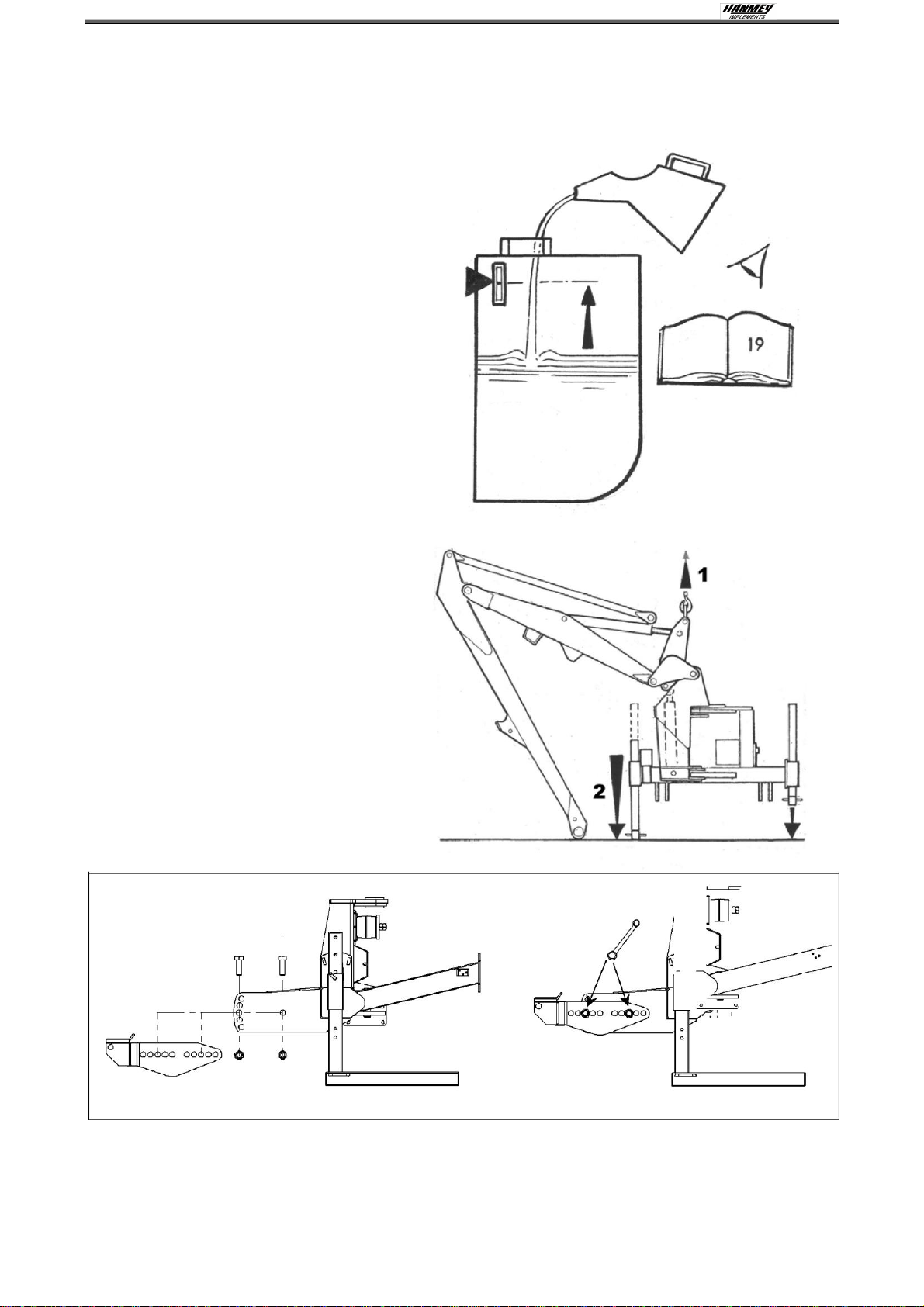
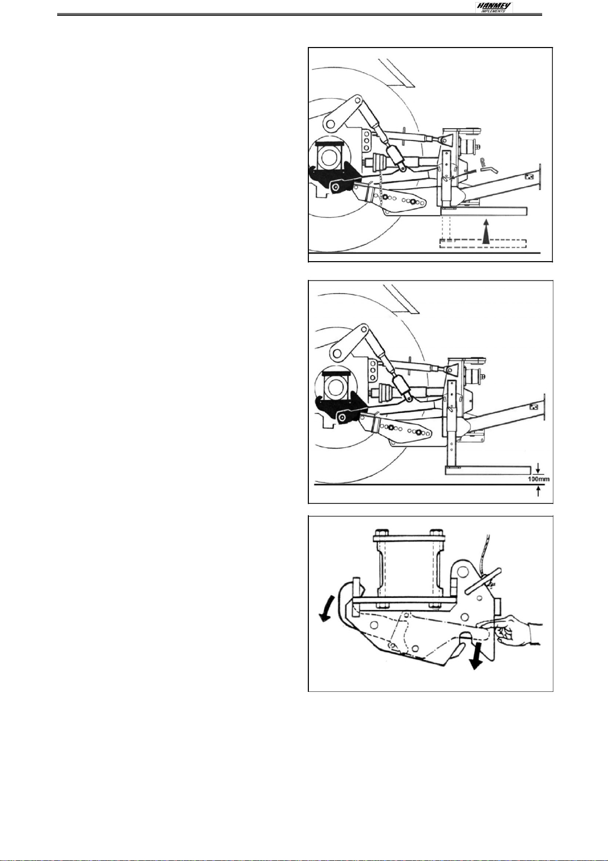
INITIAL ATTACHMENT TO TRACTOR
The machine will be delivered in a partially dismantled condition, secured with transport
strap and banding.
Choose a firm level site.
Remove the transport strap, banding
straps and loose items.
Raise the machine using overhead
lifting equipment with a minimum
capacity of 1500kg SWL.
LEAVE IN POSITION AT THIS STAGE.
Lower the legs and pin in position
selecting the holes that position the
machines gearbox stub shaft approx.
75 mm below the tractors P.T.O. shaft.
Note: Leg pin position used.
Unbolt stabiliser from machine and
remove the stabiliser nose quadrant pin.
Locate axle-mounting arms onto the mainframe and secure in position using the correct
nuts and bolts supplied, tighten nuts when correct hole location has been selected - see
following page for details on mounting hole selection.
11
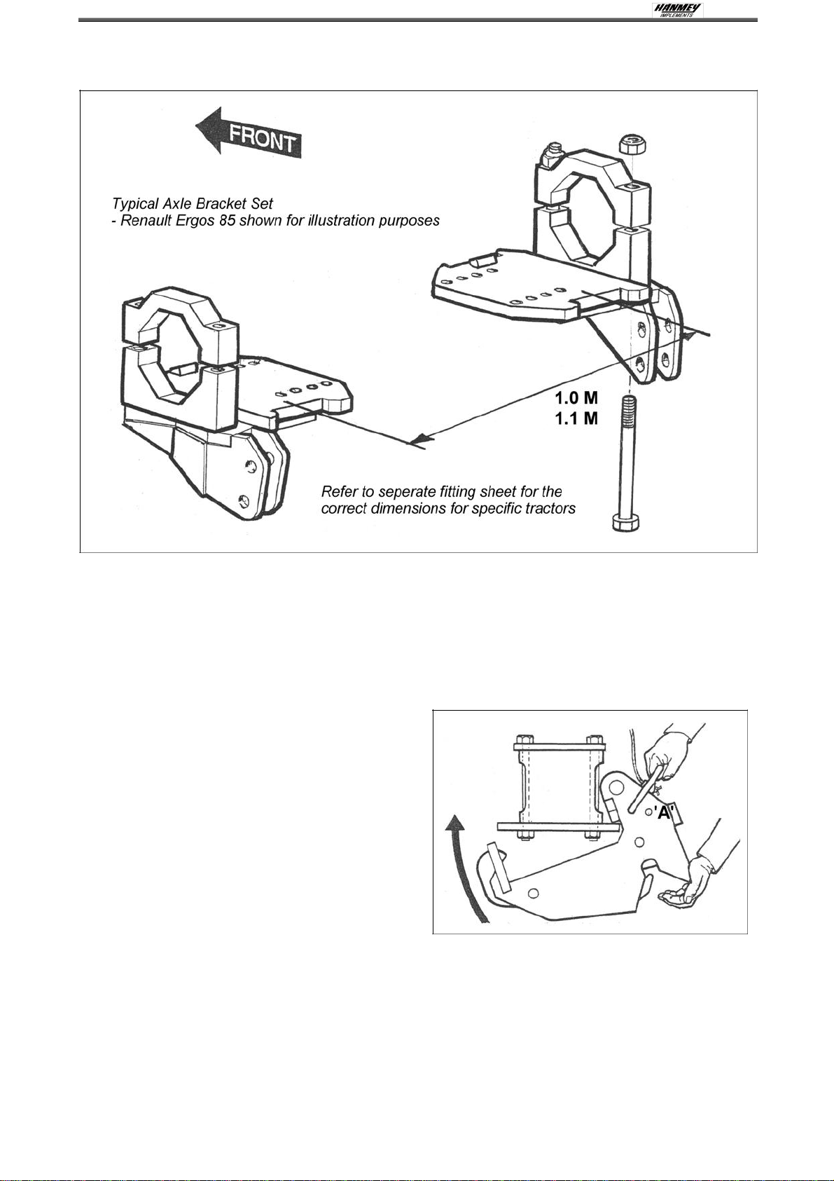
AXLE BRACKET/CATCH ASSEMBLY - FITTING BY DEALER
Bolt axle plates to the tractor axle at either 1.0 M or 1.1 M apart - this may necessitate the
to removal of the tractor's check chains and/or assister ram brackets, if this is the case, the
axle plate will include replacement brackets for these functions.
The axle brackets supplied will be accompanied by a fitting sheet with instruction for their
attachment to your tractor, follow the instructions exactly as they are specific to your
particular make and model of tractor. Replace assister ram(s) if fitted.
Hook the catch assemblies onto the rear
of the axle plates, push firmly against
the plate and vigorously pivot the catch
in a forward and up direction until the
spring loaded hook 'snaps' into position.
Pass the release cords up into the cab.
NOTE:
On some tractors fitted with auxiliary fuel tanks,
there is insufficient space for the spring
catches to be fitted, in these instances special
axle brackets and catches with a
'pin on' facility are available on request. Ensure catch-locking pin 'A' is removed.

12
STANDARD TYPE BRACKETS
With the frame in the vertical position, measure dimensions 'A' and 'B', subtract 'B' from 'A'
to obtain measurement 'X'. Measure dimension 'C'.
Select mounting holes which position the mounting bars in the end of the latch arms so
that dimension 'D' equals dimension 'C' minus measurement 'X' and also when the draft
link is horizontal and the rocking draft pin is in the upright position dimensions 'E' and 'F'
are equal.
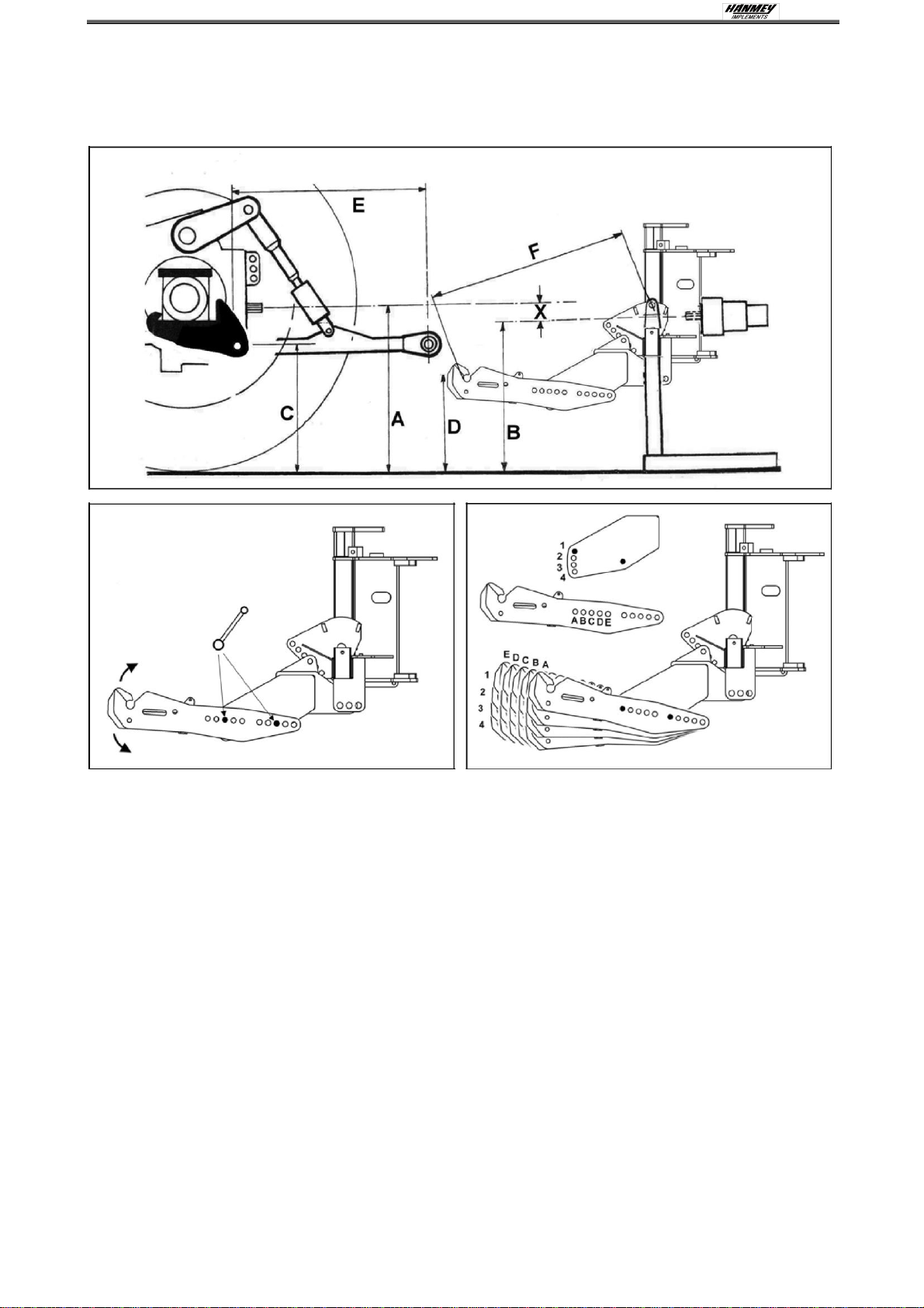
13
ALTERNATIVE TYPE BRACKETS
With the frame in the vertical position, measure dimensions 'A' and 'B', subtract 'B' from 'A'
to obtain measurement 'X'. Measure dimension 'C'.
Select mounting holes which position the mounting bars in the end of the latch arms so
that dimension 'D' equals dimension 'C' minus measurement 'X' and also when the draft
link is horizontal and the rocking draft pin is in the upright position dimensions 'E' and 'F'
are equal.

14
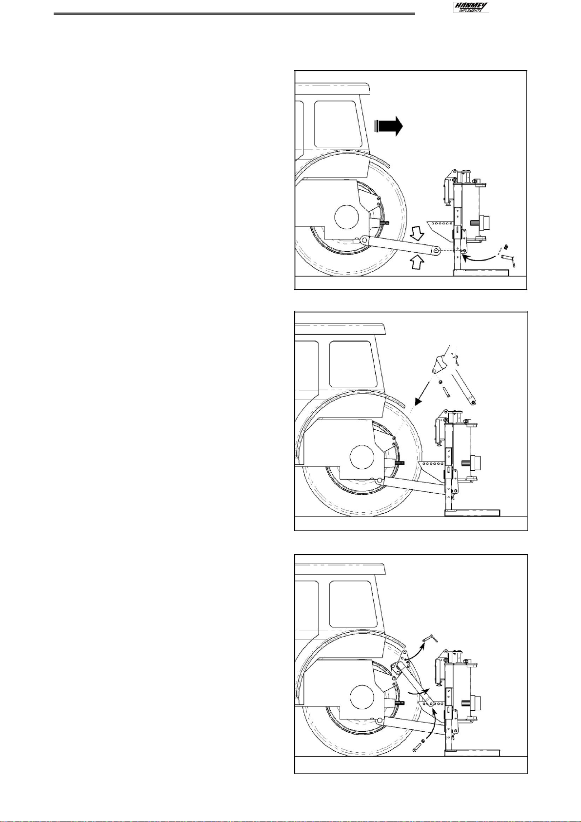
TRACTOR ATTACHMENT - BY CUSTOMER OR DEALER
Reverse tractor squarely into position
adjacent to the machine and connect the
draft links to the machine - maneuver tractor
until both draft pin rockers are vertical.
Raise the machine on the tractors
linkage sufficient only for the latch bar to
fully engage in the axle catch.
WARNING!
The quadrant lever or machine controls
must only be operated from the tractor
seat. Ensure no one is standing close
to or within the linkage arms or bars.
NOTE:
Be aware -as lift occurs the machinery
may tilt slightly.
Insert catch lock pins –refer to
diagrams below for specific type
Locking Pins on this type of bracket
pass through the arms above the
latches and are secured with linch pins.
Standard Type Bracket
Alternative Type Bracket
15
Raise the machine on the tractors
linkage until the frame is vertical.
Fit top link.
Measure PTO shaft and cut to dimension
shown (distance ‘A’ minus 75mm) - see
diagram opposite and refer to maintenance
section for further details.
NOTE:
For subsequent use on a different tractor
measure again - there must be a minimum
of 6" (150mm) of shaft overlap.

16
Fit PTO shaft into position.
Attach the torque chains to a convenient
location to prevent rotation of the shaft
guards.
Fit machine controls into the cab - refer to
the specific page on this subject for further
details.
FIRST FITTING ONLY - for Dealer reference
Request assistance. Operate 'Lift up' on machine controls sufficient only for the dipper
arm to clear the ground. Pivot out the dipper until the tension link can be reconnected.
17
Raise the stand legs into the work position
and secure with their pins - see diagram
opposite.
Tighten check chains and/or stabiliser bars.
The machine should now be carefully
operated throughout its full range of
movements to check hoses are not being
strained, pinched, chafed or kinked, and
that all movements are functioning correctly.
The machine can now be folded into the
transport position ready to proceed to the
work site - Refer to the section on Transport
Position for details on this subject.
REMOVAL FROM TRACTOR
Select a firm safe site to remove
the machine
Locate parking legs into their housings.
NOTE: The correct, and most stable,
position for removing the machine from the
tractor is with the arm positioned to the rear
of the machine.
Position the flail head on the ground
directly to the rear of the machine at
approximately half reach.
Disengage PTO.
Remove latch security pins.
Take machine weight on draft links
sufficient only to allow the top link to
be disconnected.
Open axle catches using the release
cord and lower the machine.
Disconnect draft links and remove the
PTO shaft.
Remove control units from the tractor cab
and stow clear of the ground in a location
where they are protected from the
weather or risk of accidental damage.
Drive tractor away from machine.
Locate parking legs into their housings.
Remove the axle catches from the tractor.
Replace check chains / stabiliser bars
–The axle plates can remain permanently in position.
STORAGE
If the machine is to be left standing for extended periods of time, lightly coat the exposed
portions of the ram rods with grease. Subsequently this grease should be wiped off before
the rams are next moved. If the machine is to be stored outside tie a piece of tarpaulin or
canvas over the control assembly - do not use a plastic bag as this can lead to corrosion
in the unit.
18
TRACTOR ATTACHMENT –Linkage Mounted Machines
With the machine positioned on a firm
level site and securely supported,
maneuver the tractor squarely up to
the machine with the tractor’s draft
links set to a height level with the
machines lower link brackets.
Fig.1
Connect the tractor’s draft links to the
machine’s lower link brackets, retain
in position with the linkage and lynch
pins supplied. Ensure that the same
‘hole position’ is selected on each side
of the machine.
NOTE: The hole selected on the lower
link bracket should be the rear most
that permits the machine to be
mounted without fouling the tractor.
LIFTING EQUIPMENT MAY NOW BE
REMOVED.
Fit and secure stabiliser nose into the
tractors top link selecting the highest
position available avoiding any load
sensing properties. Fig.2
NOTE: The bolt on nose of the
stabiliser is reversible in order to
accommodate variations of tractor
linkage designs.
Figure 1
Figure 2
1
2
Remove the ‘R’ clip and quadrant pin
from stabiliser and swing it rearwards
to locate with one of the holes on the
mainframe -select the hole that is
furthest away from the tractor and
secure loosely with the bolt provided.
DO NOT TIGHTEN AT THIS STAGE
and DO NOT REPLACE QUADRANT
PIN AT THIS STAGE.
Fig.3
Figure 3
1
2
3
19
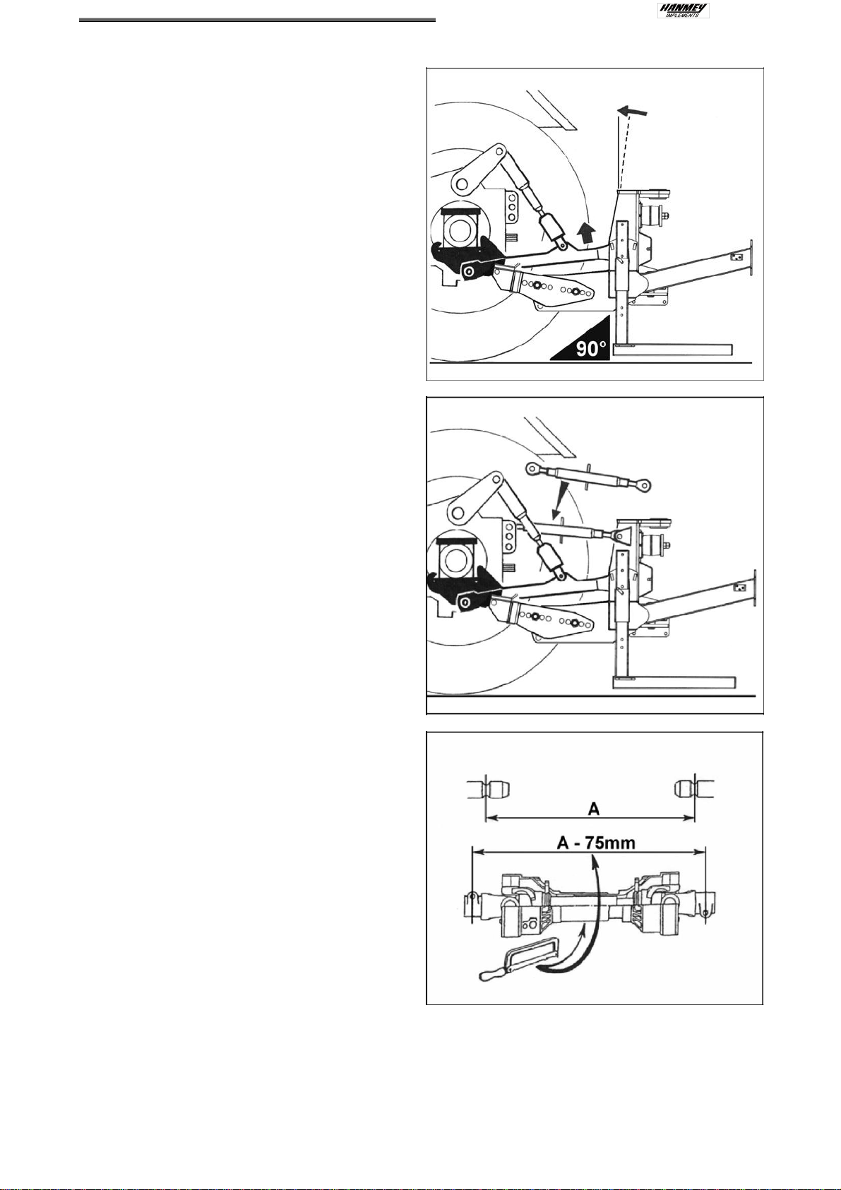
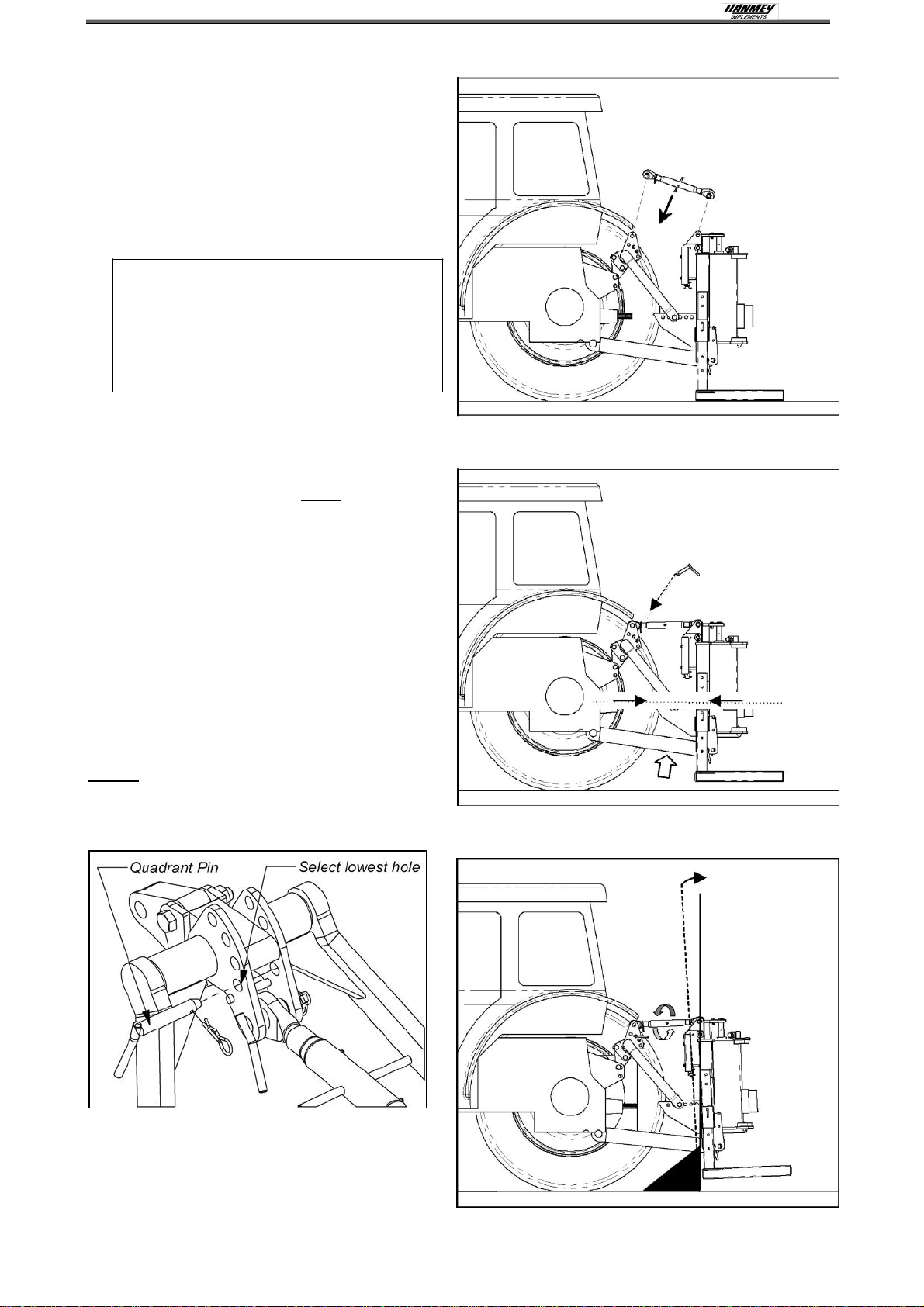
Fit the machines top link.
Fig.4
Raise the machine on the tractors
linkage to a position where the tractor
PTO and the machines gearbox stub
shaft are approximately in line with
each other. Note: As lift occurs be
aware the machine may tilt slightly.
WARNING
The quadrant lever or machine
controls must be operated from
the tractor seat. Ensure no one is
standing on or between the
linkage arms or bars.
Replace the stabiliser quadrant pin
and secure with the ‘R’ clip.
Fig.5
NOTE: The quadrant pin must be fitted in
the lowest hole on the stabiliser in order
that it acts as a ‘bottom stop’ - this will
prevent the machine from dropping when
stopped and permit the tractor’s inbuilt
transport protection system to function
correctly during operation and
transportation.
Ensure the tractor’s linkage is in ‘position
control’ and the linkage raised sufficiently
to hold the hedgecutter at the correct
height and remove the load from the
quadrant pin.
Never fit the quadrant pin in a location
hole that locks the stabiliser as this can
cause damage to the machine and/or
tractor.
Adjust the top link to bring the
machine frame into the vertical
position.
Fig.6
Figure 4
Figure 5
2
1
Figure 6
90º

20
Fully tighten the stabiliser lower bolts
Fig.7
Figure 7
Measure the PTO shaft and cut to the
dimension shown –the finished length
of the PTO shaft should be 75mm (3”)
less than the measured distance ‘A’ -
between tractor shaft and gearbox
stub shaft - to enable fitting.
Fig.8
NOTE:
For subsequent use with different
tractors measure again, there must be
a minimum shaft overlap of 150mm
(6”).
Fit PTO in position and attach the
torque chains to a convenient location
to prevent the shaft guards from
rotating.
Fig.9
Figure 8
Figure 9
This manual suits for next models
2
Table of contents
Popular Trimmer manuals by other brands


ATIKA
ATIKA HS 680-61 - operating manual

Black & Decker
Black & Decker LHT341 instruction manual

Qualcast
Qualcast HQ-CG 3.6 Original operating instructions

Shindaiwa
Shindaiwa T242X Owner's/operator's manual

Echo
Echo SRM-225 - PARTS CATALOG SERIAL NUMBER... parts catalog

Makita
Makita UR013G instruction manual