manuals.online logo
Brands
  1. Home
  2. •
  3. Brands
  4. •
  5. Hanna Instruments
  6. •
  7. Multimeter
  8. •
  9. Hanna Instruments HI98195 User manual

Hanna Instruments HI98195 User manual

This manual suits for next models

3

Other Hanna Instruments Multimeter manuals

Hanna Instruments HI 9828 User manual

Hanna Instruments

Hanna Instruments HI 9828 User manual

Hanna Instruments HI98199 User manual

Hanna Instruments

Hanna Instruments HI98199 User manual

Hanna Instruments Edge User manual

Hanna Instruments

Hanna Instruments Edge User manual

Hanna Instruments HI 9829 User manual

Hanna Instruments

Hanna Instruments HI 9829 User manual

Hanna Instruments HI 9564 User manual

Hanna Instruments

Hanna Instruments HI 9564 User manual

Hanna Instruments HI 9564 User manual

Hanna Instruments

Hanna Instruments HI 9564 User manual

Hanna Instruments HI 9813-5 User manual

Hanna Instruments

Hanna Instruments HI 9813-5 User manual

Hanna Instruments HI98194 User manual

Hanna Instruments

Hanna Instruments HI98194 User manual

Hanna Instruments HI 98402 User manual

Hanna Instruments

Hanna Instruments HI 98402 User manual

Popular Multimeter manuals by other brands

Fluke 106 user manual

Fluke

Fluke 106 user manual

VAR DV-71600 manual

VAR

VAR DV-71600 manual

Agilent Technologies 34420A user guide

Agilent Technologies

Agilent Technologies 34420A user guide

Fluke 83 user manual

Fluke

Fluke 83 user manual

Hameg HM 8012 manual

Hameg

Hameg HM 8012 manual

Mastech MY70 Operation manual

Mastech

Mastech MY70 Operation manual

Steren MUL-300 user manual

Steren

Steren MUL-300 user manual

Somogyi Elektronic home SMA 92 instruction manual

Somogyi Elektronic

Somogyi Elektronic home SMA 92 instruction manual

Gossen MetraWatt METRAmax 6 operating instructions

Gossen MetraWatt

Gossen MetraWatt METRAmax 6 operating instructions

PeakTech 4000 Procedure of calibration

PeakTech

PeakTech 4000 Procedure of calibration

YOKOGAWA 90050B user manual

YOKOGAWA

YOKOGAWA 90050B user manual

Fluke 8846A Programmer's manual

Fluke

Fluke 8846A Programmer's manual

Tempo Communications MM200 instruction manual

Tempo Communications

Tempo Communications MM200 instruction manual

APPA 607 user manual

APPA

APPA 607 user manual

Elenco Electronics CM-1555 operating instructions

Elenco Electronics

Elenco Electronics CM-1555 operating instructions

Mastech MS8238C user manual

Mastech

Mastech MS8238C user manual

SDAR 830A, 830B, 830D, 830C user manual

SDAR

SDAR 830A, 830B, 830D, 830C user manual

RS PRO RS-9519BT instruction manual

RS PRO

RS PRO RS-9519BT instruction manual

manuals.online logo
manuals.online logoBrands
  • About & Mission
  • Contact us
  • Privacy Policy
  • Terms and Conditions

Copyright 2025 Manuals.Online. All Rights Reserved.

HI98194,
HI98195, HI98196
Multiparameter Meters
pH/mV, ORP, EC, TDS, Resistivity,
Salinity, Seawater σ, Dissolved
Oxygen, Atmospheric Pressure
and Temperature
INSTRUCTION MANUAL
www. .com information@itm.com1.800.561.8187
Thank you for choosing a Hanna Instruments product.
Please read this instruction manual carefully before using the instrument.
This manual will provide you with the necessary information for correct
use of the instrument, as well as a precise idea of its versatility.
If you need additional technical information, do not hesitate to e‑mail
us at or view our worldwide contact list at
Dear Customer,
All rights are reserved. Reproduction in whole or in part is prohibited without the written consent
of the copyright owner, Hanna Instruments Inc.
www. .com information@itm.com1.800.561.8187
3
TABLE OF CONTENTS
5
5
7
8
10
15
17
19
23
6
10
11
16
18
22
24
25
26
26
28
CHAPTER 1 - INTRODUCTION
Preliminary Examination .....................................................................................................
Model Identification ...........................................................................................................
General Description ............................................................................................................
Display and Keypad Description ...........................................................................................
CHAPTER 2 - QUICK START
Sensor and Probe Installation ..............................................................................................
Basic Operation .................................................................................................................
Help Function .....................................................................................................................
CHAPTER 3 - SPECIFICATIONS
System Specifications ..........................................................................................................
Probe Specifications ............................................................................................................
Sensor Specifications ...........................................................................................................
CHAPTER 4 - PROBE INSTALLATION
Sensor Descriptions .............................................................................................................
Sensor Preparation/Activation ..............................................................................................
Sensor Installation ..............................................................................................................
CHAPTER 5 - INITIALIZATION AND MEASUREMENT
Battery Installation .............................................................................................................
Meter Initialization .............................................................................................................
Measurement Mode ............................................................................................................
Setup Menu Structure .........................................................................................................
CHAPTER 6 - PARAMETER SETUP MENU
Select Parameters ...............................................................................................................
Parameter Units ..................................................................................................................
Parameter Coefficients .........................................................................................................
www. .com information@itm.com1.800.561.8187
4
29
31
35
41
30
34
38
42
46
50
47
52
54
45
46
49
50
53
56
57
TABLE OF CONTENTS
CHAPTER 7 - CALIBRATION MODE
Calibration Mode.................................................................................................................
Quick Calibration ................................................................................................................
pH Calibration ....................................................................................................................
Relative mV Calibration .......................................................................................................
Dissolved Oxygen Calibration (HI98194, HI98196 only) ........................................................
Conductivity Calibration (HI98194, HI98195 only) ................................................................
Temperature Calibration ......................................................................................................
Atmospheric Pressure Calibration ..........................................................................................
CHAPTER 8 - SYSTEM SETUP
Meter Setup .......................................................................................................................
Probe Setup .......................................................................................................................
CHAPTER 9 - STATUS
Meter Status ......................................................................................................................
Probe Status ......................................................................................................................
GLP Data ...........................................................................................................................
CHAPTER 10 - LOGGING MODE
Logging Mode ....................................................................................................................
Logging Menu Structure ......................................................................................................
Logging On Meter ...............................................................................................................
Log Recall ..........................................................................................................................
Log Notes ..........................................................................................................................
CHAPTER 11 - PC CONNECTION
PC Connection ....................................................................................................................
CHAPTER 12 - TROUBLESHOOTING / ERROR MESSAGES
Troubleshooting/Error Messages............................................................................................
APPENDIX
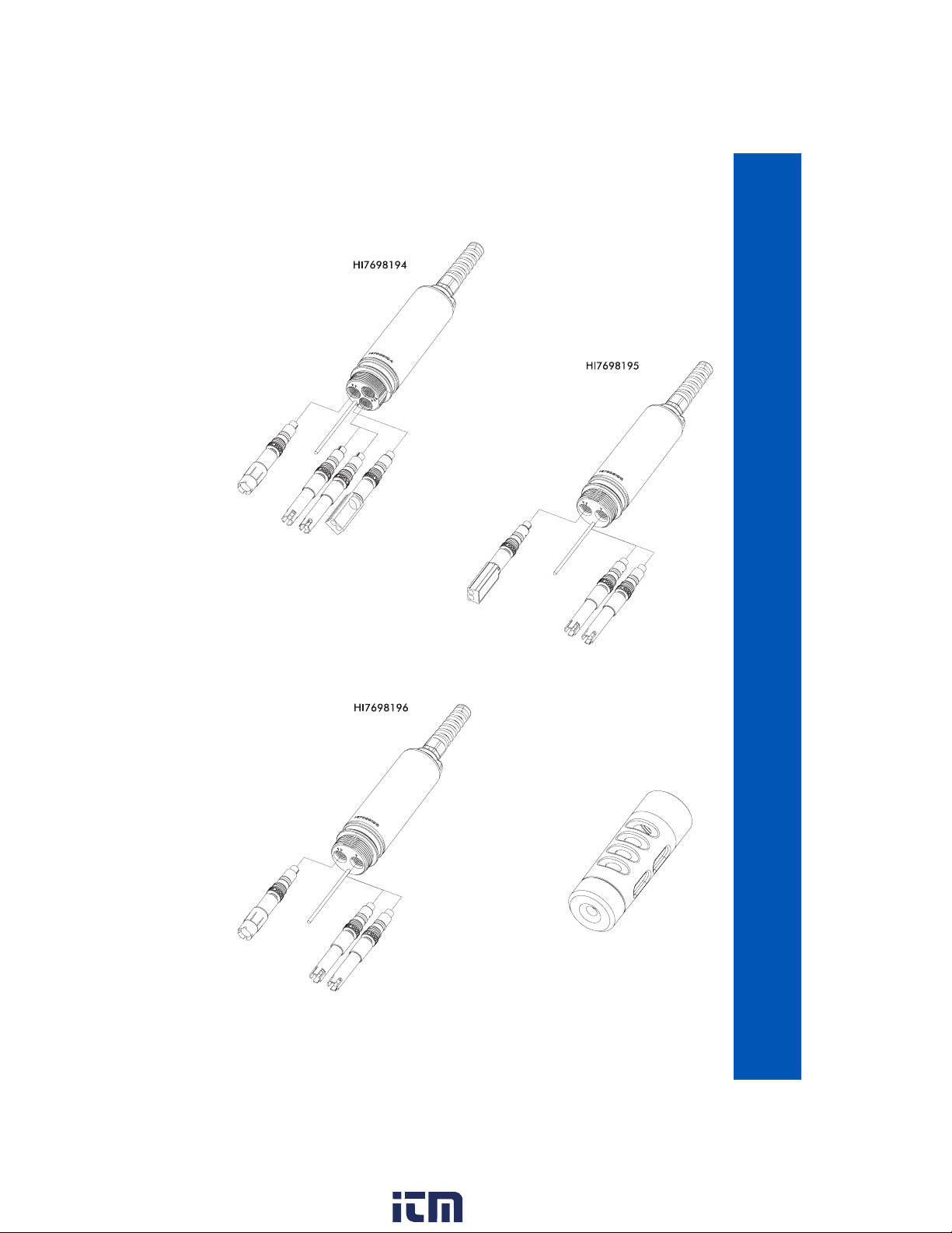
A ‑ PROBE MAINTENANCE....................................................................................................
B ‑ PROBE DEPLOYMENT ....................................................................................................
C ‑ ACCESSORIES ...............................................................................................................
42
59
61
www. .com information@itm.com1.800.561.8187
5
Remove the instrument from the packing material and examine it carefully to make sure that no
damage has occurred during shipping. If there is any damage, please contact your local Hanna
Instruments Office.
METERS WITH PROBES ‑ packaged together in a sturdy carrying case with:
• HI9298194 PC Application Software
• HI7698290 calibration beaker
• HI9828‑20 calibration solution (230 mL)
• USB cable
• 1.5V AA batteries (4 pcs.)
• probe maintenance kit
• appropriate probe shield
• specified sensors
• Instruction Manual and Quick Reference Guide
• Certificate
Note: Save all packing materials until you are sure that the instrument functions correctly.
Any damaged or defective items must be returned in their original packing material with
the supplied accessories.
Chapter 1 - INTRODUCTION
PRELIMINARY EXAMINATION MODEL IDENTIFICATION
HI98194 pH/mV, ORP, EC, TDS, Resistivity, Salinity, Seawater σ, Dissolved Oxygen,
Atmospheric Pressure and Temperature Multiparameter meter with HI7698194
probe.
HI98195 pH/mV, ORP, EC, TDS, Resistivity, Salinity, Seawater σ, Atmospheric Pressure and
Temperature Multiparameter meter with HI7698195 probe.
HI98196 pH/mV, ORP, Dissolved Oxygen, Atmospheric Pressure and Temperature
Multiparameter meter with HI7698196 probe.
www. .com information@itm.com1.800.561.8187
6
GENERAL DESCRIPTION
HI9819X is a portable logging multiparameter system (instrument, probe) that monitors up to 14
different water quality parameters (7 measured, 7 calculated).
The microprocessor‑based intelligent multisensor probes allows measurement of many water quality
parameters such as pH, ORP, dissolved oxygen, conductivity and temperature with data logging. The
system is easy to setup and easy to use.
The HI9819X features a graphic, backlit display that automatically sizes the digits to fit the screen
with on‑screen graphing capability. Each parameter is fully configurable.
HI9819X was designed to withstand harsh environments and is the ideal solution for field measure‑
ments of lakes, rivers and sea.
The meter meets IP67 standards (30 minute immersion at a depth of 1 m) and the multisensor probe
meets IP68 standards (continuous immersion in water).
Main features of the HI9819X systems:
• Rugged meter and probe
• Easy to use
• Measure up to 14 parameters and display of up to 12 parameters
• Waterproof protection (IP67 for the meter and IP68 for the probe)
• Graphic LCD with backlight
• Built‑in barometer for D.O. concentration compensation (HI98194, HI98196 only)
• Quick calibration feature
• Measurement check to eliminate any erroneous readings
• Auto recognition of probe and sensors
• Log‑on‑demand and automatic logging (up to 45,000 samples) on meter for all parameters
• Graphical display of logged data
• USB interface for PC communication
• Auto‑ranging for EC readings (HI98194, HI98195 only)
• Good Laboratory Practice feature, the last 5 calibrations are automatically stored
• Field‑replaceable sensors with color coded caps
• Meter is powered with alkaline batteries
www. .com information@itm.com1.800.561.8187
7
DISPLAY AND KEYBOARD DESCRIPTION
1. Graphic LCD
2. Battery level indicator
3. Softkeys
4. On/Off key: turn the meter on and off
5. Lamp key: turn the backlight on and off
6. Alphanumeric keyboard: insert alphanumeric codes
7. / Arrow keys: scroll the displayed options/message
8. HELP key: obtain information about the displayed screen
9. ESC key: return to the previous screen
10. Softkey functions defined on display
www. .com information@itm.com1.800.561.8187
8
Chapter 2 - QUICK START
• Sensor O‑Rings must be lubricated with the supplied grease prior to installation.
• HI769819X probes have 2 or 3 sensor connectors sockets identified with color‑coded triangles:
• Connector 1 (red): For either pH/ORP, pH sensor
• Connector 2 (white): For dissolved oxygen sensor (HI98194, HI98196 only)
• Connector 3 (blue): For EC sensor (HI98194, HI98195 only)
• Position the connector key towards the center of the probe, make sure the connector is seated
correctly (the sensor will no longer move freely) before tightening the locking threads.
• To protect the sensors, screw the protective shield onto the probe body.
• With the meter off, connect the probe to the instrument input on the top of the meter. Align the
pins and key then push the plug into the socket and tighten the thread.
• Turn the meter on by pressing the On/Off key. The meter will automatically recognize the probe
and the installed sensors and identify them on the probe status screen.
• Press Measure to view the measurement screen.
SENSOR AND PROBE INSTALLATION
www. .com information@itm.com1.800.561.8187
9
SENSOR AND PROBE INSTALLATION
www. .com information@itm.com1.800.561.8187
10
BASIC OPERATION
The main operating modes for HI9819X are measurement, logging and setup.
The measurement screen can be configured to display a single measurement or up to 12 simultane‑
ous measurements by using the numbers 1‑7 on the keypad. Use the / keys to scroll through
the measurements not being displayed. See page 24 for more details.
The measurement units will blink if the system has not been calibrated and the measurement number
will blink when the reading is out of range.
Press Log to display the logging menu. You can either log a single sample on the meter or start an
interval log on the meter. See Chapter 10 for more details.
Press Menu to enter setup mode. You can configure which parameters you want to measure, calibrate
the sensors, change system settings and view the meter and probe status.
HELP FUNCTION
HI9819X features context sensitive HELP, which provides useful information regarding the displayed
screen.
Simply press the HELP key to access this function, then use the / keys to scroll through the
message.
To escape from the HELP window, press the HELP key again or ESC.
www. .com information@itm.com1.800.561.8187