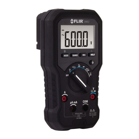
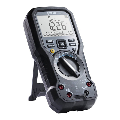
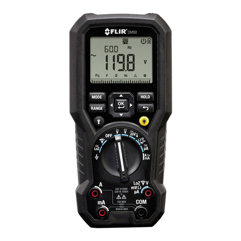
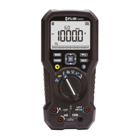
FLIR DM90 User manual

QUICK START GUIDE
FLIR MODEL DM90
True RMS Industrial MultiMeter

FLIR DM90 –QUICK START GUIDE Document Identifier: DM90-QS-en-US_AA
GETTING STARTED - EN
USER MANUAL LOCATION: The detailed User Manual is located on the support.flir.com web site (download
tab). Translations of User Manual and Quick Start Guides are also available on the web site. Please read the
entire User Manual to gain a thorough understanding of the meter before use. Please Register for Extended
Warranty and Product Updates at www.flir.com/testwarranty
METER DESCRIPTION
1. Work Light and Non-Contact Voltage Detector areas
2. LCD Display
3. Navigation/Selector pad
4. MODE Button
5. RANGE Button
6. Work Light Button
7. Rotary Function Switch
8. Positive (+) Probe Input Jack for A(Current).
9. Positive (+) Probe Input Jack for mA (Current).
10. COM (-) Probe Input Jack
11. Positive (+) Probe Input Jack for all inputs except Aand mA
12. Display Backlight Button
13. Cancel/Return Button
14. Display HOLD Button
Note: Battery compartment, tilt stand located on back of meter.
Test lead holder attaches to back of meter as described in User
Manual.
FUNCTION SWITCH POSITIONS
Detect AC voltage through the non-contact sensor at the top of the meter.
Measure voltage through low impedance loaded probe inputs.
Meter is switched OFF and in full power-saving mode.
FLEX Direct: Auxiliary channel for Flexible Current clamp meters or generic clamp adaptors.
Measure AC voltage (V) through the probe inputs.
Measure DC voltage (V) through the probe inputs.
Measure low voltage (mV) through the probe inputs.
Measure temperature with adaptor connected to probe inputs.
Measure resistance, continuity, capacitance, diode through the probe inputs.
Measure current through the probe inputs (A or mA).
Measure µA current through the probe inputs.

FLIR DM90 –QUICK START GUIDE Document Identifier: DM90-QS-en-US_AA
FUNCTION BUTTONS
Use to select a sub-function of the primary function.
From Auto range mode, press to select Manual range mode.
From Manual range mode, short press to change the range. Long press to activate Auto range mode.
Press to toggle Hold and normal display mode. Use the Settings menu to select Data or Auto hold.
Use the selector/navigation pad to navigate mode and advanced function menus.
Press to cancel/exit a screen in the Settings menu (no function in the normal mode).
Press to enable/disable display backlight. The display backlight is ON when the meter is powered up.
Press to enable/disable the work light.
DISPLAY SYMBOLS
Low Impedance mode
Auto power off function enabled
Measured voltage is > 30 VAC/DC
AC current or voltage
Non-Contact Voltage detector
DC current or voltage
MAX (Maximum) reading
Flex Clamp Direct Input
MIN (Minimum) reading
Continuity function
AVG (Average) reading
Diode test function
PEAK MAX value displayed
MENU BAR ICON: VFD mode
PEAK MIN value displayed
P
MENU BAR ICON: Peak mode
Auto range mode
MENU BAR ICON: MIN-MAX-AVG
Data Hold mode
Hz
MENU BAR ICON: Frequency mode
Primary display (large digits)
MENU BAR ICON: Relative mode
Secondary display (smaller digits)
MENU BAR ICON: Settings mode
Battery voltage status
Work light active
Bar Graph Display

FLIR DM90 –QUICK START GUIDE Document Identifier: DM90-QS-en-US_AA
MODE BUTTON OPERATION
Switch Position
MODE button sequence of operation
AC → DC → °F or °C
Resistance → Continuity → Capacitance → Diode
AC → DC
AC → DC
MENU BAR ICONS
There are (6) functions in the Menu Bar represented by the following icons:
VFD (low pass filter)
MAX-MIN-AVG memories
Relative mode
P
Peak Max and Peak Min (Auto Hold)
Hz
Frequency measurements
Settings mode
1. Only one icon flashes at a time to indicate the cursor position.
2. Use the Left / Right buttons to move the cursor.
3. Press OK to activate/deactivate the selected function. A frame appears around the activated function.
4. In the AC Voltage/AC mV/AC Current/Flex/LoZ modes, all icons shown above are available.
5. For DC Current/Voltage, Resistance, Continuity, Capacitance, Temperature, and Diode only the MAX-MIN-
AVG, Relative, and Settings icons are available.
METER POWER
Set the function switch to any position to switch the meter ON. If the battery indicator shows that the
battery voltage is low or if the meter does not power on, replace the batteries. The meter enters sleep mode
after 20 minutes. The time can be set from 1 ~ 99 minutes (or OFF) in the Settings menu.
AUTO/MANUAL RANGE
In Auto range mode, the meter automatically selects the most appropriate measurement scale. In Manual
range mode, the desired range (scale) can be adjusted by the user. Auto range mode is the default mode of
operation. When a new function is selected with the function switch, the starting mode is Auto range and
the indicator is displayed.
To enter Manual range mode, short press the button. To change the range, press the button
repeatedly until the desired range is displayed. To return to the Auto range mode, long press the
button until the Auto Range indicator is again displayed.
MIN-MAX-AVG RECORDING
The meter captures and displays the minimum, maximum, and average readings, updating only when a
higher/lower value is registered. The meter also averages the total sum of all recorded values.
1. Navigate to the MIN-MAX AVG icon using the left/right arrow buttons and enable the mode by
pressing OK.
2. Use the up/down buttons to cycle through the minimum, maximum, and average reading displays. The
corresponding icons are displayed: , , or
3. Press to pause. Press again to continue.

FLIR DM90 –QUICK START GUIDE Document Identifier: DM90-QS-en-US_AA
VFD (ACV and ACA only)
High-frequency noise is eliminated from the voltage measurement through the use of a low-pass filter (for
AC voltage/current). Navigate to the VFD icon and enable/disable VFD mode by pressing the OK button.
RELATIVE MODE
The difference between the real-time reading and a stored reference value is displayed in the main display.
The reference value is displayed in the secondary display (smaller digits above the larger, primary display).
Navigate to using the arrow buttons and enable the mode by pressing OK. The value displayed at the
time the OK button is pressed is the reference value.
PEAK MAX and PEAK MIN (ACV and ACA only)
The meter captures and displays the positive and negative peak values, and updates only when a
higher/lower value is registered.
1. Navigate to Pand enable Peak mode by pressing OK.
2. Use the up/down navigation buttons to toggle Peak Max and Peak Min.
3. In Peak Max mode, the indicator is displayed. In Peak Min mode, the indicator is displayed.
4. Press the button to pause the Peak mode. Press again to continue.
SETTINGS MENU
1. Navigate to the Settings icon using the arrow buttons and access the menu by pressing the OK button.
2. Use the up/down buttons to step through the modes, use the left/right arrows to change a setting, and
press OK to activate and save the changes. Refer to the list below:
Auto power off (APO): Use the left/right arrows to set the time period after which the meter enters
sleep mode (1 ~ 99 minutes, or set to OFF to disable APO). The factory default is 20 minutes.
Auto backlight off (BLit): Use the left/right arrows to set the time period after which the backlight
automatically turns off (1 ~ 99 minutes or set to OFF to disable). The factory default is 5 minutes.
Auto hold / Data hold (hold: A.H. or d.H.): Use the left/right arrows to select Auto hold or Data hold
mode.
Use the left/right arrows to select the default (dEF) temperature unit of measure oC or oF.
Diode (dio) mode (Smart or Classic modes). Use the left/right buttons to select Classic (C.d.) or Smart
mode (S.d.).
Coarse Resolution (C.r. ON/OFF). Use the arrow buttons to select ON (to limit the least significant
display digits) or OFF (to display with maximum resolution).
Reset (rSt): Press OK to revert to the factory default settings.
DATA HOLD and AUTO HOLD
The meter has two HOLD modes: classic Data Hold and Auto Hold. To select Data Hold or Auto Hold as the
default, please use the Settings menu. Refer to the paragraphs below for instructions on using the Hold
modes.
Data Hold: In Data Hold mode, the primary meter display freezes the last reading. To enter/exit Data Hold
mode, press the button. In Hold mode, the indicator is displayed.
Auto Hold Mode: In Auto hold mode, the secondary display freezes the last reading and the icon flashes.
The real-time reading is displayed on the primary display. The held reading will not change unless the
difference between the held reading and any new reading is > 50 digits. The Auto hold function will capture
a reading if the reading is greater than the trigger level: > 1% of full scale range for
Voltage/Current/Capacitance. For Resistance/Diode/Temperature the trigger is automatic as long as ‘OL’ is
not displayed. To enter/exit Auto hold mode, press the button.

FLIR DM90 –QUICK START GUIDE Document Identifier: DM90-QS-en-US_AA
FREQUENCY MEASUREMENTS (ACV and ACA only)
The frequency is displayed in the upper display area and the ACV or ACA is displayed in the lower, main
display. To display only the frequency, navigate to the Hzicon using the arrow buttons and enable the mode
by pressing OK.
MEASUREMENT DIAGRAMS

FLIR DM90 –QUICK START GUIDE Document Identifier: DM90-QS-en-US_AA

FLIR DM90 –QUICK START GUIDE Document Identifier: DM90-QS-en-US_AA
CLASSIC
DIODE MODE

FLIR DM90 –QUICK START GUIDE Document Identifier: DM90-QS-en-US_AA
SMART DIODE TEST MODE
In SMART Diode mode the meter checks diodes using an alternating test signal sent through the diode in
both directions. This allows the user to check the diode without having to reverse polarity manually. The
meter display will show ± 0.400 ~ 0.800V for a good diode, ‘bAd’ for a shorted diode, and ‘O.L’ for an opened
diode. To toggle the SMART and CLASSIC DIODE modes, please use the meter’s Settings Menu. Only the
Classic Diode mode is illustrated in the Measurement section of this Quick Start; for more details on SMART
DIODE please refer to the more comprehensive User Manual available at www.support.flir.com web site
(download tab) and to the illustration below:
SMART DIODE TEST RESULTS

FLIR DM90 –QUICK START GUIDE Document Identifier: DM90-QS-en-US_AA
Corporate Headquarters
FLIR Systems, Inc.
2770 SW Parkway Avenue
Wilsonville, OR 97070 USA
Telephone: +1 503-498-3547
Customer Support
Technical Support Website http://support.flir.com
Customer Support Telephone +1 855-499-3662 option 3 (toll free)
Certificate of Conformity and ISO-9001 Quality Management System
FLIR Commercial Systems, Inc., an ISO 9001 certified company, hereby certify that our instruments meet or
exceed the specifications stated in the user manuals.
This instrument was produced under the stringent guidelines of FLIR Commercial System’s certified ISO 9001
Quality Management System from design to delivery. All instruments are calibrated and inspected to meet the
stated specifications.
FLIR Commercial Systems, Inc. inspects its incoming shipments using an approved sampling plan with an
Acceptable Quality Level (AQL). All incoming inspections are performed using test equipment that is traceable
to National Standards. Our ISO 9001 Quality Management System extends to aftermarket support where
tested quality procedures are applied to customer support, service, calibration and repair processes.
This instrument will provide years of reliable service when used in accordance with the instructions provided
in the User Manual. To have this device certified please contact your local service center.
Quality Assurance Management
Publication Identification No.: DM90-QS-en-US
Release version: AA
Release Date: 2017 January
Language: en-US
Copyright ©2017 FLIR Systems, Inc.
All rights reserved including the right of reproduction in whole or in part in any form.
www.flir.com
Other manuals for DM90
2
Table of contents
Other FLIR Multimeter manuals

FLIR
FLIR Extech Instruments 410 User manual

FLIR
FLIR MR160 User manual

FLIR
FLIR EXTECH INSTRUMENTS MA120 User manual

FLIR
FLIR DM284 User manual

FLIR
FLIR DM93-2 User manual

FLIR
FLIR DM284 User manual

FLIR
FLIR DM90 User manual

FLIR
FLIR CM83 User manual

FLIR
FLIR Extech Instruments MN16 User manual

FLIR
FLIR DM92-NIST User manual

FLIR
FLIR DM6 Series User manual

FLIR
FLIR Extech Instruments MultiMaster MM560A User manual

FLIR
FLIR DM93-2 User manual

FLIR
FLIR Extech EX510 User manual

FLIR
FLIR EXTECH INSTRUMENTS DM110 User manual

FLIR
FLIR Extech Instruments MG302 User manual

FLIR
FLIR EXTECH INSTRUMENTS EX520 User manual

FLIR
FLIR DM93 User manual

FLIR
FLIR DM284 User manual

FLIR
FLIR DM166 User manual