Hanna HI 96711 User manual
1
HI 96711
Free & Total Chlorine
Fast Tracker
Ion Specific Meter
www.hannainst.com
Instruction Manual

2
TABLE OF CONTENTSTABLE OF CONTENTS
TABLE OF CONTENTSTABLE OF CONTENTS
TABLE OF CONTENTS
HI 96711 is warranted for two years against defects in workmanship and materials when used
for its intended purpose and maintained according to instructions. This warranty is limited to
repair or replacement free of charge.
Damage due to accidents, misuse, tampering or lack of prescribed maintenance is not covered.
If service is required, contact the dealer from whom you purchased the instrument. If under
warranty, report the model number, date of purchase, serial number and the nature of the failure.
If the repair is not covered by the warranty, you will be notified of the charges incurred. If the
instrument is to be returned to Hanna Instruments, first obtain a Returned Goods Authorization
number from the Technical Service Department and then send it with shipping costs prepaid.
When shipping any instrument, make sure it is properly packed for complete protection.
To validate your warranty, fill out and return the enclosed warranty card within 14 days from the
date of purchase.
WARRANTYWARRANTY
WARRANTYWARRANTY
WARRANTY
Dear Customer,
Thank you for choosing a Hanna Instruments product. This manual will provide you with the
necessary information for correct use of the meter.
Please read this instruction manual carefully before using the instrument.
or see the back side of this manual for our worldwide sales and technical service contacts.
This instrument is in compliance with directives.
WARRANTY.......................................................................................................................... 2
PRELIMINARY EXAMINATION................................................................................................. 3
GENERAL DESCRIPTION ........................................................................................................ 4
FAST TRACKER FEATURE ....................................................................................................... 4
ABBREVIATIONS .................................................................................................................. 5
SPECIFICATIONS ................................................................................................................... 6
PRECISION AND ACCURACY ................................................................................................... 6
PRINCIPLE OF OPERATION .................................................................................................... 7
FUNCTIONAL DESCRIPTION ................................................................................................... 9
GUIDE TO DISPLAY CODES ................................................................................................... 11
GENERAL TIPS FOR AN ACCURATE MEASUREMENT ............................................................... 14
MEASUREMENT PROCEDURE .............................................................................................. 15
VALIDATION PROCEDURE .................................................................................................... 17
CALIBRATION PROCEDURE .................................................................................................. 18
SETUP............................................................................................................................... 20
LOGGING ........................................................................................................................... 23
TAG INSTALLATION ............................................................................................................. 26
BATTERIES REPLACEMENT .................................................................................................. 26
ACCESSORIES .....................................................................................................................27
RECOMMENDATIONS FOR USERS ........................................................................................ 27

3
PRELIMINARY EXAMINATIONPRELIMINARY EXAMINATION
PRELIMINARY EXAMINATIONPRELIMINARY EXAMINATION
PRELIMINARY EXAMINATION
Please examine this Product carefully. Make sure the instrument is not damaged. If any damage
has occurred during the shipment, please notify your dealer.
This HI 96711 Ion Specific Meter is supplied complete with:
• Two Sample Cuvets and Caps
• Three CAL CHECK™ cuvets (HI 95701-11 & HI 95711-11)
• Reagent powder packets (HI 93701-0 & HI 93711-0) (10 packets each)
• Tissue for wiping the cuvets
• Five Tag holders with Tags (HI 920005)
• Batteries (4 pcs.)
• Scissors
• Instruction Manual
• Quick Reference Guide
• Instrument Quality Certificate
• Rigid carrying case
Note:Save all packing material until you are sure that the instrument works correctly. Any
defective item must be returned in the original packing with the supplied accessories.

4
HI 96711 is an auto diagnostic portable microprocessor meter that benefits from Hanna’s years of
experience as manufacturer of analytical instruments. It has an advanced optical system based on a
special tungsten lamp and a narrow band interference filter that allows most accurate and repeatable
readings. All instruments are factory calibrated and the electronic and optical design minimizes the
need of frequent calibration.
With the powerful CAL CHECK™ validation function you are able to validate good performance of
your instrument at any time. The validation procedure is extremely user friendly. Just use the
exclusive Hanna ready-made, NIST traceable standards to verify the performance of the instrument
and recalibrate if necessary.
All instruments are splash proof and the lamp and filter units are protected from dust or dirt by a
transparent cup. This makes the instruments fulfill field applications.
Display codes aid the user in routine operation. Acoustic signals are used to make the instrument
more user-friendly. The meter has an auto shut-off feature that will turn off the instrument after 10
minutes of non-use or after 1 hour if left in
calibration mode
.
The meter uses an exclusive positive-locking system to ensure that the cuvet is in the same position
every time it is placed into the measurement cell. It is designed to fit a cuvet with a larger neck
making it easier to add both sample and reagents. The cuvet is made from special optical glass to
obtain best results.
The HI 96711 meter measures the free and total chlorine (Cl2) content in water samples in the
0.00 to 5.00 mg/L (ppm) range. The method is an adaptation of the USEPA Method 330.5 for
wastewater and Standard Method 4500-Cl G for drinking water.
The reagents are in powder form and are supplied in packets. The amount of reagent is precisely
dosed to ensure the maximum repeatability.
GENERAL DESCRIPTION
GENERAL DESCRIPTIONGENERAL DESCRIPTION
GENERAL DESCRIPTIONGENERAL DESCRIPTION
GENERAL DESCRIPTION
FAST TRACKER FEATUREFAST TRACKER FEATURE
FAST TRACKER FEATUREFAST TRACKER FEATURE
FAST TRACKER FEATURE
Hanna is the first manufacturer of colorimeters that has decided to add the unique T.I.S.-Tag
Identification System to our Fast Tracker Ion Specific Meters, to meet the more restrictive needs for
traceability of our clients. This means that from now on you can benefit all advantages of this system
for your colorimetric measurements and data management.
The system is designed for scientific and industrial applications, or to prove during safety audits and
inspections that samples have been truly taken on preestablished locations.
The system is as easy to install as to operate. Just fix the so-called iButton® tags near your sampling
sites that need to be checked often, and with this the T.I.S. is setup. The tag contains a computer chip
embedded in a durable stainless steel can. It is designed to withstand the harsh environments,
indoors or outdoors. The number of tags that can be installed is practically unlimited, because each
tag has a unique identification code.

5
ABBREVIATIONSABBREVIATIONS
ABBREVIATIONSABBREVIATIONS
ABBREVIATIONS
°C degree Celsius
USEPA US Environmental Protection Agency
°F degree Fahrenheit
LCD Liquid Crystal Display
mg/L milligrams per liter. mg/L is equivalent to ppm (parts per million)
mL milliliter
RTC Real Time Clock
RH Relative Humidity
iButton®®
®®
®is registered Trademark of “MAXIM/DALLAS semiconductor Corp.”
Immediately after installation of the tags you can start collecting data. Use the Fast Tracker Ion
Specific Meter to take measurement and memorize the test result by pressing the Log-on-Demand
key. Then, the meter will ask for the tag identification. Simply touching the iButton® with the
matching connector on the Fast Tracker does identify and authenticate logging, time and date stamp
events.
The power of the Fast Tracker and T.I.S. features resides in the PC application. Download all test data
to your PC and use our HI 92000 Windows®compatible application software for further data
management. You can sort or filter all your collected test data on different criteria like on a specific
sampling location, parameter, date and time intervals, or fix range to filter measured values. The
data can be plotted in a graph, exported to other common Windows®applications or printed for
reporting purpose.
It is possible to add also new tags later on, thus increasing an already existing database. Each time
the PC software recognizes a not already register tag it will ask for a description of the new sampling
location.

6
Range Free Cl20.00 to 5.00 mg/L
Total Cl20.00 to 5.00 mg/L
Resolution 0.01 mg/L from 0.00 to 3.50 mg/L; 0.10 mg/L above 3.50 mg/L
Precision ±0.02 mg/L @ 1.00 mg/L
Typical EMC Deviation ±0.01 mg/L
Light Source Tungsten lamp with narrow band interference filter @ 525 nm
Light Detector Silicon Photocell
Method Adaptation of the USEPA Method 330.5 and Standard Method
4500-Cl G. The reaction between chlorine and DPD reagent causes a
pink tint in the sample
LOG Memory 99 records
Serial Interface RS232 @ 9600 baud rate
Environment 0 to 50°C (32 to 122°F); max 95% RH non-condensing
Power supply 4 x 1.5V AA alkaline batteries
Auto Shut-off After 10 minutes of non-use in
measurement mode
After 1 hour of non-use in
calibration mode
Dimensions 216 x 83 x 65 mm (8.5 x 3.26 x 2.55”)
Weight 420 g (17 oz.)
REQUIRED REAGENTS
Code Unit Description Quantity/test
HI 93701-0 Free Cl2Free Chlorine Reagent 1 packet
HI 93711-0 Total Cl2Total Chlorine Reagent 1 packet
SPECIFICATIONSSPECIFICATIONS
SPECIFICATIONSSPECIFICATIONS
SPECIFICATIONS
Precision is how closely repeated measurements
agree with each other. Precision is usually
expressed as standard deviation (SD).
Accuracy is defined as the nearness of a test
result to the true value.
Although good precision suggests good accuracy,
precise results can be inaccurate. The figure
explains these definitions. In a laboratory using
a standard solution of 1.00 mg/L chlorine and a
representative lot of reagent, an operator obtained
with a single instrument a standard deviation
of 0.02 mg/L.
PRECISION AND ACCURACYPRECISION AND ACCURACY
PRECISION AND ACCURACYPRECISION AND ACCURACY
PRECISION AND ACCURACY

7
Absorption of light is a typical phenomenon of interaction between electromagnetic radiation and
matter. When a light beam crosses a substance, some of the radiation may be absorbed by
atoms, molecules or crystal lattices.
If pure absorption occurs, the fraction of light absorbed depends both on the optical path length
through the matter and on the physical-chemical characteristics of the substance, according to the
Lambert-Beer law:
–log I/Io=ελ
c d
or
A
=ελc d
Where:
–log I/Io=Absorbance (A)
Io=intensity of incident light beam
I=intensity of light beam after absorption
ελ=molar extinction coefficient at wavelength λ
c=molar concentration of the substance
d=optical path through the substance
Therefore, the concentration “c” can be calculated from the absorbance of the substance as the
other factors are known.
Photometric chemical analysis is based on the possibility to develop an absorbing compound
from a specific chemical reaction between sample and reagents. Given that the absorption of a
compound strictly depends on the wavelength of the incident light beam, a narrow spectral
bandwidth should be selected as well as a proper central wavelength to optimize measurements.
The optical system of Hanna's HI 96 colorimeters series is based on special subminiature
tungsten lamps and narrow-band interference filters to guarantee both high performance and
reliable results.
Block diagram (optical layout)
PRINCIPLE OF OPERATIONPRINCIPLE OF OPERATION
PRINCIPLE OF OPERATIONPRINCIPLE OF OPERATION
PRINCIPLE OF OPERATION

8
A microprocessor controlled special tungsten lamp emits radiation which is first optically conditioned
and beamed to the sample contained in the cuvet. The optical path is fixed by the diameter of the
cuvet. Then the light is spectrally filtered to a narrow spectral bandwidth, to obtain a light beam of
intensity Ioor I.
The photoelectric cell collects the radiation Ithat is not absorbed by the sample and converts
it into an electric current, producing a potential in the mV range.
The microprocessor uses this potential to convert the incoming value into the desired measuring
unit and to display it on the LCD.
The measurement process is carried out in two phases: first the instrument is zeroed and then the
actual measurement is performed.
The cuvet has a very important role because it is an optical element and thus requires particular
attention. It is important that both the measurement and the calibration (zeroing) cuvets are
optically identical to provide the same measurement conditions. Whenever possible use the same
cuvet for both. It is necessary that the surface of the cuvet is clean and not scratched. This to
avoid measurement interference due to unwanted reflection and absorption of light. It is
recommended not to touch the cuvet walls with hands.
Furthermore, in order to maintain the same conditions during the zeroing and the measuring
phases, it is necessary to close the cuvet to prevent any contamination.

9
FUNCTIONAL DESCRIPTIONFUNCTIONAL DESCRIPTION
FUNCTIONAL DESCRIPTIONFUNCTIONAL DESCRIPTION
FUNCTIONAL DESCRIPTION
1) Serial interface connector.
2) Tag reader connector.
3) Cuvet Holder.
4) Liquid Crystal Display (LCD).
KEYPAD DESCRIPTION
5) CAL CHECK bi-functional key, press shortly to validate the actual calibration, or hold the key
for 3 seconds to enter calibration.
6) RCL/SETUP bi-functional key, press shortly to view log records, or hold the key for 3 seconds to
enter setup.
7) LOG/CFM, to save the log records or to confirm the selected option.
8) READ/TIMER bi-functional key, press shortly to take measurements, or hold the key for 3
seconds to start a pre-programmed countdown prior to measurement.
9) ZERO/ , to zero the instrument prior to measurement or to display the content of a record.
10) /DEL, to change down the parameter program (P1 or P2), to decrease set values or to
scroll the log and to restore the factory calibration.
11) , to change up the parameter program (P1 or P2), to increase set values or to scroll the log.
12) ON/OFF, to turn the instrument ON and OFF.
INSTRUMENT DESCRIPTION

10
DISPLAY DESCRIPTION
1) Four digit main display.
2) Measurement unit.
3) Three and a half digit secondary display.
4) “TIME” and “DATE”: appear with time (hh:mm) and date (yyyy.mm.dd) presentation.
5) The hourglass icon: appears when the instrument is making an internal check-up.
6) Status information.
7) Battery icon: appears when the battery voltage is getting low.
BEEPER
A beeper is used for confirmation and error signals. The error signal is distinguished from
confirmation by a long beep.

11
This prompt appears for one second each time the instrument is
turned ON.
Indicates that the meter is ready to operate and zeroing can be
performed (P1 or P2). The secondary LCD shows a number which
indicates the program that is selected.
This flashing prompt appears each time the meter is performing an
internal check-up.
Indicates that the meter is performing a zero measurement and if
necesarry, auto-calibrates the light intensity.
The instrument is zeroed and a measurement can be made.
Indicates that the meter is making a measurement.
Light over range: the cuvet is not inserted correctly and an excess of
ambient light is reaching the detector. If the cuvet is properly
installed, then contact your dealer or the nearest Hanna Customer
Service Center.
The meter has lost its configuration. Contact your dealer or the
nearest Hanna Customer Service Center.
Batteries voltage is getting low and the batteries need to be
replaced.
Indicates that the batteries are dead and must be replaced. Once this
message is displayed, the instrument will lock-up. Press ON/OFF to
switch off the meter, change the batteries and restart the instrument.
GUIDE TO DISPLAY CODESGUIDE TO DISPLAY CODES
GUIDE TO DISPLAY CODESGUIDE TO DISPLAY CODES
GUIDE TO DISPLAY CODES

12
CALIBRATION MODE MESSAGES
This prompt appears each time the meter enters calibration mode.
The meter is ready for a new calibration and asks for zero
measurement.
This indicates that the meter was not calibrated by the user.
This prompt appears for one second at the end of a new calibration
to indicate that the new calibraton has been stored.
A confirmation of the factory calibration is selected.
This indicates that the user calibration was deleted.
“Error”: the concentration of the used calibration solution is not
correct. Repeat the calibration procedure with the right standard
solution, and verify it is not expired. If the calibration procedure
fails again, contact your dealer or the nearest Hanna Customer
Service Center.
LOGGING MODE MESSAGES
The blinking “READ TAG” indicates that the meter asks to read the
tag for identification of the sampling location.
Note: If the tag is not read within 20 seconds, the logging procedure
is canceled.
A record is stored without identification of the sampling location.
Indicates that the memory is full and no other record can be
stored.
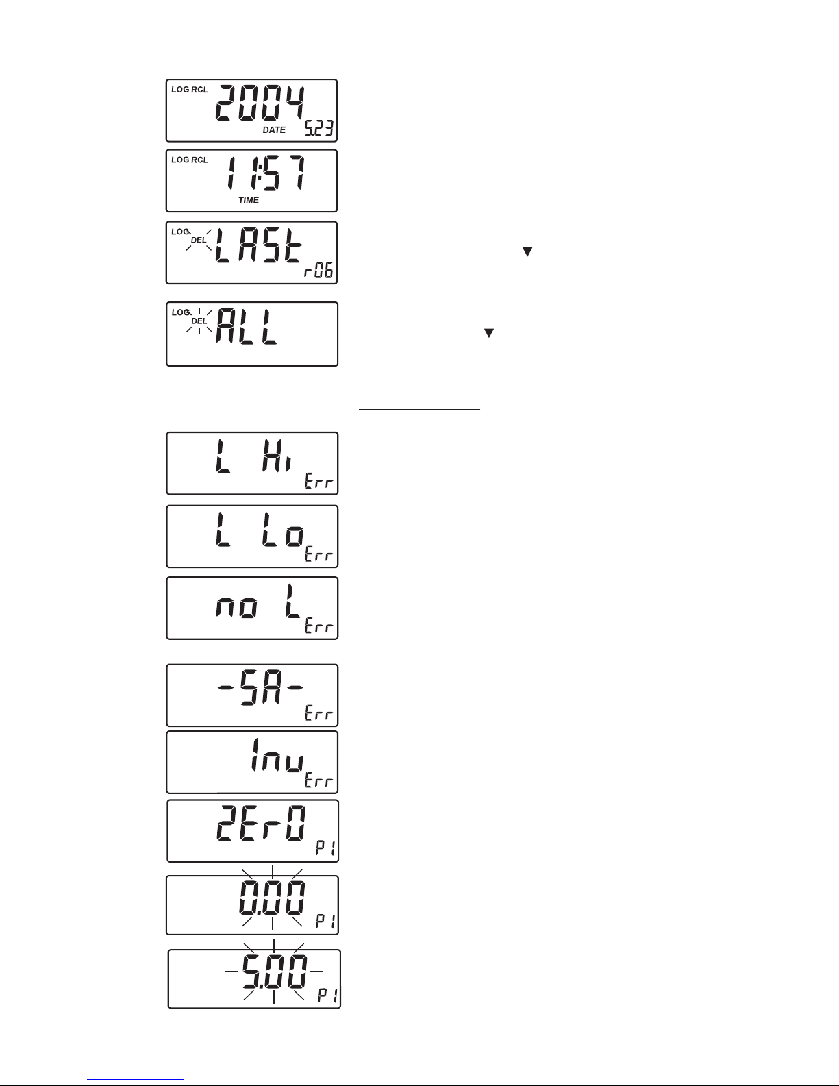
LOG RECALL MODE MESSAGES
This prompt appears when entering recall data. The records number
appear on the primary display.
13
Measurement date: year (yyyy), month (mm), day (dd).
Measurement time: hour (hh) and minutes (mm).
Delete the last record. The blinking “DEL” indicates that the last
record will be deleted if the /DEL key is pressed.
Note:To delete a record, a second confirmation is required.
Delete all records. The blinking “DEL” indicates that all records
will be deleted if the /DEL key is pressed.
Note:To delete all records, a second confirmation is required.
ERROR MESSAGES
a) on zero reading:
“Light high”: there is too much light to perform a measurement.
Please check the preparation of the zero cuvet.
“Light low”: there is not enough light to perform a measurement.
Please check the preparation of the zero cuvet.
“No Light”: the instrument cannot adjust the light level. Please
check that the sample does not contain any debris.
b) on sample reading:
There is too much light for the sample measurement. Please check
if the right sample cuvet is inserted.
“Inverted”: the sample and the zero cuvet are inverted.
“Zero”: a zero reading was not taken. Follow the instruction in the
measurement procedure for zeroing the instrument.
The sample absorbs less light than the zero reference. Check the
procedure and make sure you use the same cuvet for reference
(zero) and measurement.
A flashing value of the maximum concentration indicates an over
range condition. The concentration of the sample is beyond the
programmed range: dilute the sample and measure again.

14
GENERAL TIPS FOR AN ACCURATE MEASUREMENTGENERAL TIPS FOR AN ACCURATE MEASUREMENT
GENERAL TIPS FOR AN ACCURATE MEASUREMENTGENERAL TIPS FOR AN ACCURATE MEASUREMENT
GENERAL TIPS FOR AN ACCURATE MEASUREMENT
The instructions listed below should be carefully followed during testing, to ensure best accuracy.
• For filling correctly the cuvet: the liquid in the cuvet forms a
convexity on the top; the bottom of this convexity must be at the
same level of the 10 mL mark.
• Proper use of the powder reagent packet:
(a) use scissors to open the powder packet;
(b) push the edges of the packet to form a spout;
(c) pour out the content of the packet.
• It is important that the sample does not contain any debris. This would corrupt the reading.
• Each time the cuvet is used, the cap must be tightened to the same degree.
• Whenever the cuvet is placed into the measurement cell, it must be dry
outside, and completely free of fingerprints, oil or dirt. Wipe it
thoroughly with the supplied tissue (HI 731318) or a lint-free cloth
prior to insertion.
• Shaking the cuvet can generate bubbles in the sample, causing higher
readings. To obtain accurate measurements, remove such bubbles by
swirling or by gently tapping the vial.
• Do not let the reacted sample stand too long after reagent is added, or accuracy will be lost.
• It is possible to take multiple readings in a row, but it is recommended to take a new zero
reading for each sample and to use the same cuvet for zeroing and measurement.
• After the reading it is important to discard immediately the sample, otherwise the glass
might become permanently stained.
• All the reaction times reported in this manual are referred to 20°C (68°F). As a general rule
of thumb, they should be doubled at 10°C (50°F) and halved at 30°C (86°F).
• In order to maximize accuracy, prior to a measurement follow the validation procedure, to
be sure that the instrument is properly calibrated. If necessary, calibrate the instrument.

15
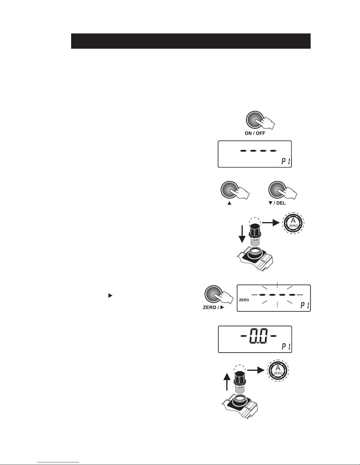
• Turn the meter on by pressing ON/OFF.
When the LCD displays “----”, the meter is ready.
On the secondary LCD “P1” or “P2” will appear,
indicating that the free or total chlorine parameter
is selected. The display code that appears is the
one of the last selected parameter.
• Select the parameter program for Free Chlorine
“P1”, or Total Chlorine “P2”, by pressing the UP
or DOWN keys.
• Fill the cuvet with 10 mL of unreacted sample, up
to the mark, and replace the cap.
• Place the cuvet into the holder and ensure that the
notch on the cap is positioned securely into the
groove.
• Press ZERO/ and “----” will blink on the display.
• Wait for a few seconds and the display will show
“-0.0-”. The instrument is now zeroed and ready
for measurement.
• Remove the cuvet from the instrument.
• Remove the cap.
• Add the content of one packet of the specific test
reagent, for:
Free Chlorine Total Chlorine
1packet of 1packet of
HI 93701-0 HI 93711-0
MEASUREMENT PROCEDUREMEASUREMENT PROCEDURE
MEASUREMENT PROCEDUREMEASUREMENT PROCEDURE
MEASUREMENT PROCEDURE
or

16
INTERFERENCES
• Bromine (positive error).
• Chlorine dioxide (positive error).
• Iodine (positive error).
• Oxidized Manganese and Chromium (positive error).
• Ozone (positive error).
Alkalinity above 250 mg/L CaCO3or acidity above 150 mg/L CaCO3will not reliably develop the full
amount of color or it may rapidly fade. To resolve this, neutralize the sample with diluted HCl or NaOH.
In case of water with hardness greater than 500 mg/L CaCO3, shake the sample for approximately 2
minutes after adding the powder reagent.
• Replace the cap and shake gently for 20 seconds
(or 2 minutes in case of seawater analysis).
• Replace the cuvet into the holder and ensure that
the notch on the cap is positioned securely into
the groove.
• Hold READ/TIMER for three seconds. The display
will show the hourglass blinking and the count-
down prior to measurement.
Alternatively, wait for:
Free Chlorine: Total Chlorine:
1 minute 2 minutes and 30
seconds
Then just press READ/TIMER. In both cases “----”
will blink during measurement.
• The instrument directly displays the concentration
in mg/L of free chlorine (P1) or total chlorine (P2)
on the LCD.
Note: If the value is over range, the maximum value
(5.00) will blink.
or
or
17
VALIDATION PROCEDUREVALIDATION PROCEDURE
VALIDATION PROCEDUREVALIDATION PROCEDURE
VALIDATION PROCEDURE
• Turn the meter on by pressing ON/OFF.
When the LCD displays “----”, the meter is ready.
On the secondary LCD “P1” or “P2” will appear,
indicating that the free or total chlorine parameter
is selected. The display code that appears is the
one of the last selected parameter.
• Select the parameter program for Free Chlorine
“P1”, or Total Chlorine “P2”, by pressing UP or
DOWN keys.
• Place the CAL CHECK™ Standard Cuvet Ainto the
holder and ensure that the notch on the cap is
positioned securely into the groove.
• Press ZERO/ and “----” will blink on the display.
• Wait for a few seconds and the display will show
“-0.0-”. The instrument is now zeroed and ready
for validation.
• Remove the cuvet.
Use the validation procedure to ensure that the instrument is properly calibrated.
Warning: Do not validate or calibrate the instrument with standard solutions other than Hanna CAL
CHECKTM Standards, otherwise erroneous results will be obtained. For accurate validation
and calibration please perform test at room temperature, 18 to 25°C (64.5 to 77.0°F).
18
CALIBRATION PROCEDURECALIBRATION PROCEDURE
CALIBRATION PROCEDURECALIBRATION PROCEDURE
CALIBRATION PROCEDURE
CALIBRATION PROCEDURE
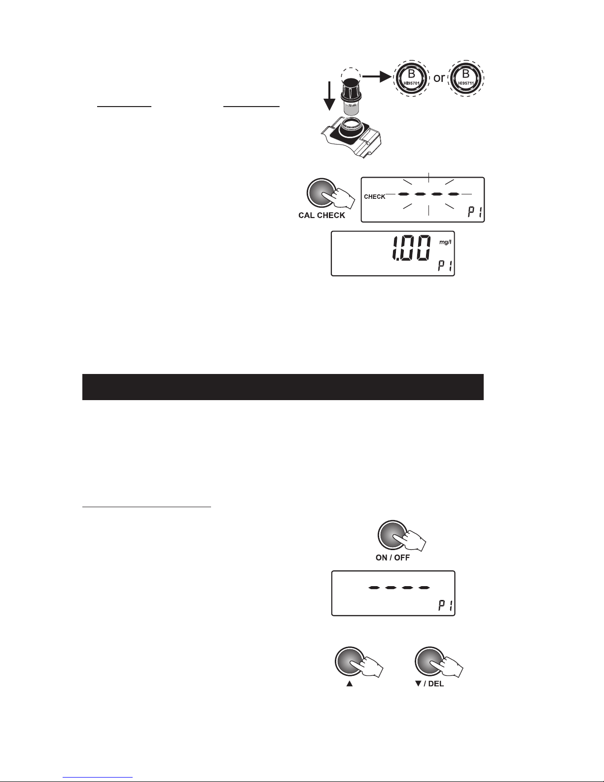
• Turn the meter on by pressing ON/OFF.
When the LCD displays “----”, the meter is ready.
On the secondary LCD “P1” or “P2” will appear,
indicating that the free or total chlorine parameter
is selected. The display code that appears is the
one of the last selected parameter.
• Select the parameter program for Free Chlorine
“P1”, or Total Chlorine “P2”, by pressing UP or
DOWN keys.
• Place the specific CAL CHECK™ Standard Cuvet B
into the holder:
Free Chlorine Total Chlorine
B, HI 95701-11 B, HI 95711-11
Ensure that the notch on the cap is positioned
securely into the groove.
• Press CAL CHECK and “----” will blink during
measurement.
• Wait for a few seconds and the display will show
the validation standard value.
Note: It is possible to interrupt the calibration procedure by pressing CAL CHECK or ON/OFF.
Warning: Do not validate or calibrate the instrument with standard solutions other than Hanna CAL
CHECK™ Standards, otherwise erroneous results will be obtained. For accurate validation
and calibration please perform test at room temperature, 18 to 25°C (64.5 to 77.0°F).
Note: The reading should be within specifications as reported on the CAL CHECK™ Standard Certificate.
If the value is found out of specifications, please check that the cuvets are free of fingerprints, oil
or dirt and repeat validation. If results are still out of specifications, then recalibrate the
instrument.
or
19
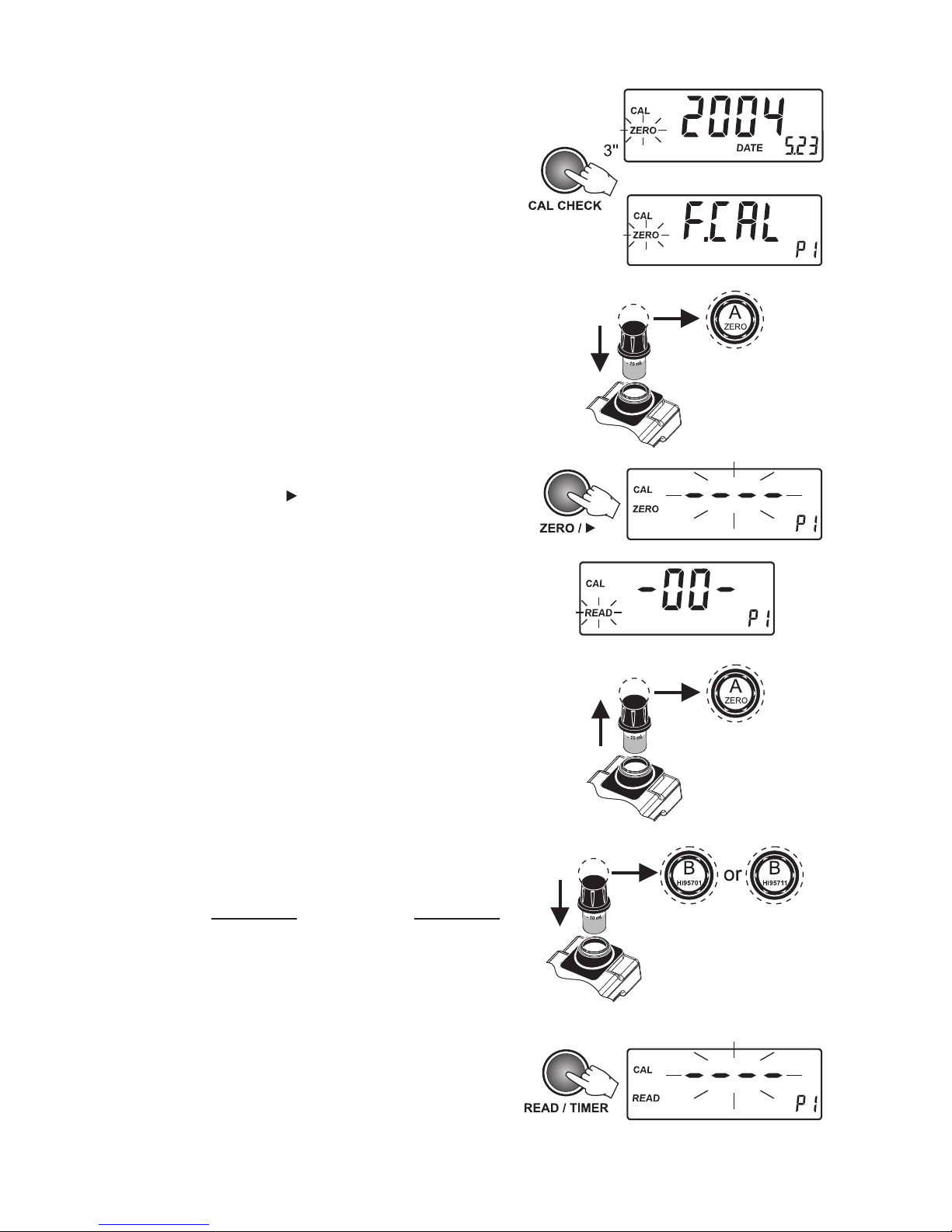
• Enter the calibration mode by holding the CAL
CHECK key for three seconds. The date of the last
calibration appears (e.g. 2004 05 23). “F.CAL”
means that the factory calibration is selected.
Note:At this moment it is possible to restore Factory
Calibration (see instructions, page 20).
• Place the CAL CHECK™ Standard Cuvet Ainto the
holder and ensure that the notch on the cap is
positioned securely into the groove.
• Press ZERO/ and “----” will blink on the display.
• After a few seconds the display will show “-0.0-”.
The meter is now zeroed and ready for calibration.
• Remove the cuvet.
• Place the specific CAL CHECK™ Standard Cuvet B
into the holder:
Free Chlorine Total Chlorine
B, HI 95701-11 B, HI 95711-11
Ensure that the notch on the cap is positioned
securely into the groove.
• Press READ/TIMER and “----” will blink on the
display.
or
or

20
• Turn the meter on by pressing ON/OFF.
• Enter setup by holding the RCL/SETUP key for three
seconds. The current date appears on the LCD.
• Use the UP or DOWN keys to switch between time
and date.
SETUPSETUP
SETUPSETUP
SETUP
• The instrument will show for two seconds the CAL
CHECK standard value and then “Stor” to confirm that
the new calibration data has been accepted. The meter
returns automatically to the measurement mode.
Note: If the display shows “Err”, the calibration proce-
dure failed. Verify that the right CAL CHECK™
Standard Cuvet Bis inserted or that both Aand
Bcuvets are free from fingerprints or dirt.
Factory Calibration Reset
It is possible to restore factory calibration.
• Enter the calibration mode by holding CAL CHECK
for three seconds. The date of last calibration
appears on the display.
• Press /DEL and “CAL”, “DEL” will appear,
with “CFM” blinking.
• Press LOG/CFM to restore factory calibration.
The display will show for two seconds “F.CAL”
and the meter returns automatically to the
measurement mode.
Table of contents


