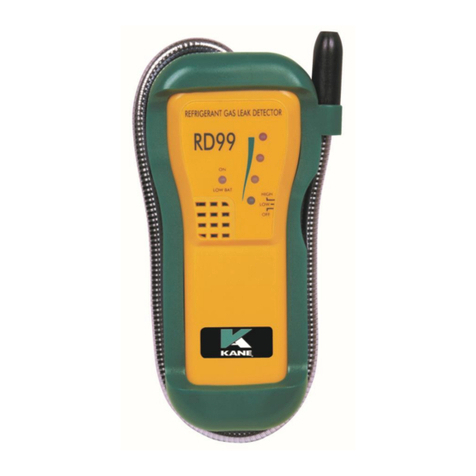
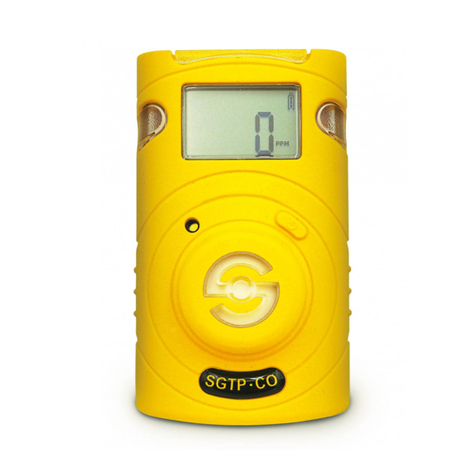
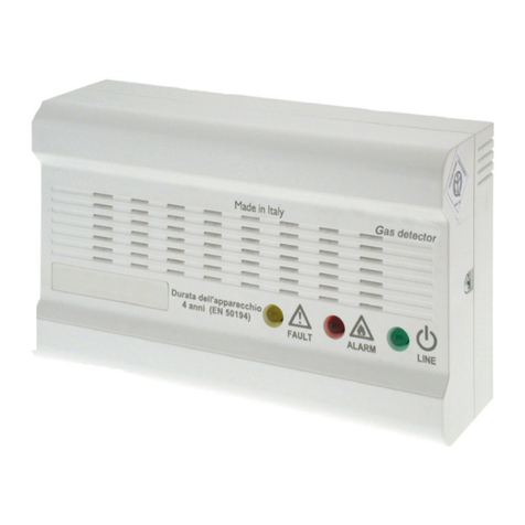
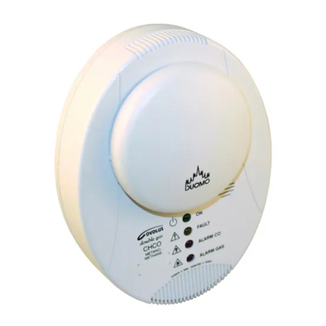
Hansen Technologies HGD-EC-NH3-100 Operating instructions

Specifications, Applications,
Service Instructions & Parts
GAS DETECTORS,
CONTROLLER
& ALERT SYSTEMS
Bulletin A100h
JANUARY 2020
For Refrigerants and
other Common Gases
Gas Detector
INTRODUCTION
Hansen Technologies offers a complete line of industrial
quality Gas Detector, Controller and Alert Systems for
refrigerants and other common gases. These state-of-
the-art gas detection products utilize a range of sensing
technologies to suit a given application. Available in
several configurations to meet various application
requirements with optimum accuracy and reliability.
APPLICATIONS
Hansen Gas Detectors are suitable for use in industrial
refrigeration engine rooms, cold storage rooms,
processing rooms, truck docks, and for relief valve vent
lines. They are also suitable for use in supermarkets,
and large institutional and commercial buildings.
Typical gas detection applications include Ammonia,
Carbon Dioxide (CO2), Hydrocarbons, HFCs, HCFCs
and CFCs.
ADVANTAGES
Hansen uses a variety of sensor element technologies
including electrochemical, semiconductor and infrared
sensors to selectively detect most gases. These sensor
elements continuously determine the level of gas present
in the surrounding environment. The analog outputs (4-
20mA or 0-10V DC) can interface with nearly any existing
monitor, computer or PLC controller.
The sensor elements are mounted internally on the
enclosure. This helps to provide quick response to
potential leaks, particularly in still air. Electronics are
sealed in a IP66 enclosure which protects them from
moisture, dust and the surrounding gases, which in the
case of ammonia can shorten the life of electronics. The
sensing elements are easily replaced.
Gas Detectors have built-in visual and audible alarms.
High level, low level and fault IA, SPDT relay outputs
are standard. Testing and recalibration procedures
are simple.
KEY FEATURES–REMOTE GAS DETECTORS
• Accurate, fast responding
• Linear 4-20mA or 0-10V DC output
• Audible alarm
• Power indicator
• SPDT alarm relays (Fail Safe Operation)
• 24V AC/DC low voltage power
• Shipped factory calibrated and tested
• CE approved
• CSA (Electrical Features Only)
KEY FEATURES–GAS DETECTION
CONTROLLER
• Visual alarm
• Audible alarm
• Power indicator
• Low level alarm relay
• High level alarm relay
• Fault relay
• Economical
• CE approved
KEY FEATURES−GAS ALERT SYSTEM
• Provides local display and alarm based on
measured target gas level via gas sensor
• Visual alarm, Amber LED light
• Audible alarm (mutable)
• Power indicator, Green
• Numeric PPM reading
• Bright LED Display
• Shipped factory calibrated and tested

2
A100h
JANUARY 2020
DO NOT SUBSTITUTE OR MODIFY
Because of the danger of introducing additional hazards,
do not install substitute parts or perform unauthorized
modifications to the equipment.
CLEANING/DECONTAMINATION
EXTERNAL SURFACE
The external surface, excluding the sensor element, can
be cleaned using light detergent and water. Do not allow
any of the solution to come in contact with the sensing
element sintered surface.
TABLE 1

3A100h
JANUARY 2020
POINT SENSOR
PLACE SENSOR
NEAR OPERATING
EQUIPMENT
PLAN VIEW
OPERATING
EQUIPMENT
PERIMETER SENSOR LOCATION
PLACE SENSORS
AROUND PERIMETER
OF LARGE ROOM
VENTILATED ROOM
AIR FLOW
PLACE SENSOR(S)
BETWEEN EQUIPMENT
AND EXHAUST FAN
GAS DETECTOR LOCATION
Detectors should be located in an accessible area
for maintenance and testing, but away from moving
equipment that could accidentally come in contact with
the sensor. Avoid thermal extremes (close to heaters)
and do not place unprotected in direct, strong drafts/
airflows, near exit doors, or areas where falling water
or condensing moisture are present. If high humidity is
always present, power up the unit as soon as possible,
as long term exposure can shorten the life of the gas
sensor element. In blast freezers, mount the gas detector
below the coil to avoid high moisture and steam during
defrost.
The two generally accepted methods of locating
detectors are “Point” and “Perimeter” detection. “Point”
detection is where detectors are located near the most
likely sources of leakage. “Perimeter” detection is where
detectors completely surround the area in question.
The size and nature of the area will help to decide
which method is the most appropriate. Air flow should
be considered in a ventilated room. Place detectors
downstream of potential leak points.
Any detector which is to be used for detecting a gas
with a vapor density greater than one (i.e. heavier than
air) should generally be located nearer ground level.
Conversely, for any lighter than air gases such as
ammonia, the detector needs to be located higher up.
Typically ammonia detectors are mounted 12˝ – 24˝ (.3 to
.5m) from the ceiling. Detectors should not be located
too close to the ceiling as hot air trapped under the
ceiling may act to buffer the target gases from reaching
the detector.
The number of detectors in each area is a function of local
codes and regulations and the customers’ guidelines
for gas detection.
12" - 24" FROM CEILING
LIGHT GASES (AMMONIA) HEAVY GASES (CO2, HALOCARBON)
MOUNT NEAR GROUND LEVEL
12" - 24" FROM CEILING
LIGHT GASES (AMMONIA)
HEAVY GASES (CO2, HALOCARBON)
MOUNT NEAR GROUND LEVEL
MOUNTING HEIGHT OF DETECTORS
FIG. 1
VENTILATED ROOM
FIG. 4
PERIMETER DETECTION
FIG. 3
POINT DETECTION
FIG. 2

4
A100h
JANUARY 2020
GAS DETECTION SYSTEM
CONFIGURATIONS
There are a number of typical installation configurations
to meet national and local codes. These diagrams are
just examples.
RELIEF VALVE VENT LINE
Often the vent line is extended high above the ground
or roof. The sensor element can be installed near the
outlet of the vent line and the gas detector electronics
REMOTE SENSOR WITH MONITOR
INDOOR OUTDOOR
VISUAL
AUDIBLE
GAS
SENSOR
VISUAL
A
UDIBLE
A
LARM ALARM
ALARM
ALARM
SIMPLE ALARM SYSTEM
INDOOR OUTDOOR
VISUAL ALARM
AUDIBLE ALARM
GAS
SENSOR
INSIDE SPACE OUTSIDE SPACE
GAS SENSOR ELEMENT
10' (3m) CABLE, MAX
WEATHER PROOF
GAS SENSOR ELECTRONICS
RELIEF LINE DISCHARGE HEADER
DRIP LEG
INSTALL
GAS SENSOR
ELEMENT WITHIN
2' (.7m) OF
DISCHARGE
VENT LINE APPLICATION
PROTECT
EXIT WITH
SUITABLE
OPTIONAL TUBING
LINE For "BUMP" TESTIN
G
GAS AND AIR PURGEROOF LINE
PIPE TEE
GAS SENSOR ELEMENT
1" X 3/4"
TO ALLOW A SMALL AMOUNT OF
AIR FLOW TO CLEAR DETECTED
GASES AND AVOID FALSE ALARMS
REDUCING BUSHING
SCREEN
STAND ALONE CONTROL
The Hansen Gas Detector can operate as a stand alone
device. All that is needed is a 24V AC/DC power supply
LOCAL AND REMOTE VISUAL/AUDIBLE
ALARM
Sometimes it may be advantageous to have both
local and remote displays and alarms. A display/
FIG. 5
FIG. 6
FIG. 7
INSIDE ROOM OUTSIDE ROOM
mounted at a convenient height for servicing. A small
length of tubing can be run for injecting test gas near
the sensor element. Install a plug with a small opening
to allow a small air flow to clear fugitive gases and
detected gas after a release. Hansen recommends the
alarm setting at 5000 PPM.
For water diffuser systems where the relief valve vent
piping is diverted into a water diffusion tank, install the
vent line detector on the diffusion tank exhaust vent,
not on the piping to the diffusion tank.
alarm control inside or just outside of a room can be
monitored and the same display/alarm or a Hansen
monitor in the control room can also alert the operator
to an abnormal condition in the plant.
for the gas detector and auxiliary devices for light,
horn or digital readout, such as the Hansen GAS Alert

5A100h
JANUARY 2020
INSTALLATION DIMENSIONS
INCHES (MM)
FIG. 8
#Component Desscription
1M16 Cable Glands (x6)
2Rubber Gasket (IP66 Version Only)
3Internal Alarm Buzze
4Power Connections (x2)
5Digital Connection (MODBUS)
6Analog Connection
7Tactile Switch #1
8Ribbon Cable to Sensor
9Tactile Switch #2
10 Relay 3 Connection (FAULT)
11 Relay 2 Connection (HIGH)
12 Relay 1 Connection (LOW)
13 Magnetic Switch #1
14 Magnetic Switch #2
15 M20 Cable Glands (x2)
GAS DETECTOR COMPONENTS
FIG. 9

6
A100h
JANUARY 2020
SENSOR ELEMENT
Typical sensor element life is based on normal operating
conditions. Exposure to the target gas will shorten
these times. The typical sensor element life of the
electrochemical gas sensor element is 2 to 3 years;
typical sensor life for semiconductor element is 4 to 6
years; and typical sensor life for infrared element is 5
to 7 years. Recalibration should be performed at least
every 6 months. Calibration can be performed locally
at detector installation site. If desired results cannot be
achieved or if signal reads <1.2mA >2.1mA, steady 3mA,
replacement of the sensor element may be required.
ELECTROCHEMICAL SENSOR ELEMENT
Electrochemical sensor element measure the partial
pressure of gases under atmospheric conditions. The
monitored ambient air diffuses through a membrane
into the liquid electrolyte in the sensor. The electrolyte
contains a measuring electrode, a counter-electrode and
a reference electrode. An electronic “potentiostat” circuit
ensures a constant electrical voltage between measuring
electrode and reference electrode. Voltage, electrolyte,
and electrode material are selected to suit the gas being
monitored so that it is transformed electrochemically on
the measuring electrode and a current flows through the
sensor element. This current is proportional to the gas
concentration. At the same time, oxygen from the ambient
air reacts at the counter electrode electrochemically.
The current flowing through the sensor is amplified
electronically, digitized and corrected for several
parameters (e.g., the ambient temperature).
SEMICONDUCTOR SENSOR ELEMENT
Semiconductor or metallic oxide sensor element (MOSs)
are among the most versatile of all broad-range sensor
element. They can be used to detect a variety of gases
and vapors in low ppm or even combustible ranges.
The sensor element is made up of a mixture of metallic
oxides. They are heated to a temperature between 150°
and 300° C depending on the gas(es) to be detected.
The temperature of operation as well as the “recipe” of
mixed oxides determines the sensor element selectivity
to various toxic gases, vapors, and refrigerants. Electrical
conductivity greatly increases as soon as a diffusion
process allows the gas or vapor molecules to come in
contact with the sensor element surface. Water vapor,
high ambient humidity, temperature fluctuations, and low
oxygen levels can result in higher readings.
INFRARED SENSOR ELEMENT
The infrared (IR) gas sensor element is designed to
measure the concentration of combustible gases and
vapors in the ambient air. The principle is based on
the concentration-dependent absorption of infrared
radiation in measured gases.
The monitored ambient air diffuses through a sintered
metal material into the enclosure of an optical “bench”.
The broadband light emitted by an IR source passes
through the gas in the optical bench and is reflected
by the walls from where it is directed towards a dual-
element detector. One channel of the detector measures
the gas-dependent light transmission, while the other
channel is used as a reference. The ratio between
measurement and reference signal is used to determine
the gas concentration. Internal electronics and software
calculate the concentration and produce an output signal
IMPORTANT: Certain substances in the atmosphere to
be monitored may impair the sensitivity of the sensors.
Such substances include, but are not limited to:
• Polymerizing substances such as acrylonitrile,
butadiene and styrene.
• Corrosive compounds such as halogenated
hydrocarbons (releasing halogens such as
bromine, chlorine or fluorine when oxidized)
and halogen hydride acids as well as acidic
gaseous compounds such as sulfur dioxide and
nitrogen oxides.
• Catalyst poisons such as sulfurous and
phosphorous compounds, silicon compounds
(especially silicones), and metal-organic vapors.
LED LOGIC
The Hansen gas detectors provide external indication
of their current operational state via audible visual
feedbackand also provide relays outputs. Visual
indication of the instrument status is provided by
a single tri-color LED (Green I Red I Orange) as
indicated below:
WIRING GAS DETECTORS
Install the Hansen Gas Detector in an area where
operating personnel can easily monitor it. Refer to
Gas Detector Location on page 3 for suggestions on
proper placement of Remote Detectors.
Use two-core shielded pair, 16 to 20 AWG wire to connect
power to the gas detector. Connect the power input
wires to terminal 4. Connect the analog signal wire to
terminal 6 and/or digital sign (MODBUS) to terminal 5. The
analog 4-20mA output signal is best for long distances
to the monitor and where electrical noise is a problem.
The voltage output is for short distances within 10 feet
(3 m) of the monitor. The maximum 4-20mA cable length
is 1000 ft (300 m).
Under no circumstances should the gas detector low
voltage signal wires be in a common conduit, tray or
wiring panel with power wiring over 48 volts. Do not run
wires near variable frequency drive (VFD) equipment.
Hansen recommends backup of gas detection system
with an uninterruptable power supply to provide battery
backup in the event of a power failure.
em
•
I
-
•
-
I
•»
I
1100-2294 Rev 1 24
TABLE 3

7A100h
JANUARY 2020
• MODBUS flag for warm-up is set.
• Buzzer is off.
• Relay state is “no alarm.”
• Gas reading is invalid.
3. Observe normal operation:
• Green LED is steady on.
• MODBUS flag for warm-up is cleared.
• Buzzer is off.
• Relay state is “no alarm.”
• Gas reading is valid.
The detector may also enter several special states, these
are indicated below by the specific analog output levels
indicated:
GAS DETECTOR TESTING
Field testing of the gas detector is normally done for three
reasons. The first is to determine if the gas detector is
responding to the specific gas. This test is sometimes
called a “bump” test. The frequency of the test is usually
stated in the facilities Process Safety Management (PSM)
document, but not less than every six months.
The second reason for gas detector testing is to be sure
the gas detector is properly calibrated. Depending on
the sensor element type, the sensor element sensitivity
will change with time. In particular, electrochemical
sensor elements use a material that is depleted with
time. The length of time varies depending on the amount
of exposure to the target gas, the ambient temperature
and humidity, and changes to temperature and humidity
range. Atmospheres that are very dry or very humid will
shorten the life of a sensor element.
The third reason is to be sure the gas detector
output triggers the alarms on the monitor, PLC, Gas
Alert System, horn or lights. All gas detectors are
recommended to be recalibrated at least every 6 months.
All detectors should be recalibrated immediately after
exposure to a large concentration of the target gas.
Note: Insurance companies, local and state agencies may
require more frequent testing and calibration; refer to
insurance carrier mandates as well as local and state codes
DETECTOR BUMP TEST
A bump test is a live test of the detector to verify the
detector responds to the target gas and all connected
alarm devices are operating accordingly. Prior to test, it
is recommended all involved persons are informed about
the test as certain alarms might have to be inhibited.
1. Connect adapter and proper PPM gas cylinder to
the sensor element.
2. If desired, disable or silence audible alarms.
3. Apply a sufficiently high concentration of the
target gas to trigger alarm condition, but NOT
pure refrigerant or hydrocarbons.
MODBUS RTU RS-485 INTERFACE
For the MODBUS RS-485 network use a 16 to 24 AWG
3-core, 2 twisted pair+ ground, shielded cable with 120
ohm characteristic impedance (recommended Belden
3106A or equivalent).
The MODBUS address, baud rate, stop bit, parity and
child termination is configured through the setup menu.
No jumpers or hardware switch settings are required.
Ensure the communication parameters within the network,
including any user supplier PLC, are configured identically.
To ensure optimal performance of the MODBUS network,
ensure the following guidelines are implemented:
• Detectors are configured in a single bus topology,
connecting multiple buses in parallel or branching
multiple units from the main bus may introduce
impedance mismatches, reflections, and/or signal
distortions.
• Avoid long stubs when connecting detectors to the
bus (should be less than 3’).
• Detectors at end of bus have 120 ohm terminating
resistor enabled. Terminating resistors may be
enabled via Hansen Gas Detector App.
• A/B signal polarity is maintained throughout RS-
485 network .
• Connect cable shield to drain to physical earth or
ground at the controller only.
• Connect cable shield to (SH) terminal at sensor
• Cable shield integrity is maintained throughout RS-
485 network.
• Do not use shield connection for signal ground.
Use cable that provides dedicated ground
conductor for signal ground. Connect signal
ground to (GND) terminal of sensor.
After all wiring has been completed, power the sensor and
perform a bump test to verify instrument functionality.
START-UP SEQUENCE
After applying power, the instrument will go through a
start-up sequence (initialization, audible/visual test and
self-test sequence). After start-up sequence completes,
the instrument will enter a warm-up period to allow the
sensor element to stabilize before reporting a valid output.
1. Switch power on.
2. Observe the start-up sequence and warm-up phase:
• Green LED will blink at 0.5 HZ for about 5 minutes.
1
POWER & SIGNAL WIRING TABLE
MODEOFOPERATION
4-20mA
1-5V
0-5V
2-10V
0-10V
InstrumentFault
<1.2mA
<0.3V
N/A
<0.6V
N/A
OfflineMode/Maintenance 3mA 0.75V N/A 1.5V N/A
DriHbelowZero
3.8mA
0.95V
N/A
1.9V
N/A
MeasuringRangeExceeded
20.5mA
5.12V
5.12V
10.25V
10.25V
FaultonAnalogInterface
>21mA
> 5.25V
> 5.25V
> 10.5V
> 10.5V
1
TABLE 5
TABLE 4
1

8
A100h
JANUARY 2020
State Switch 1
(Tap)
Switch 1
(Hold)
Switch 2
(Tap)
Switch 2
(Hold)
Warm-up - -
Normal Start Zero
Calibration
Start Scan Calibration
Low Alarm Mute Buzzer Ack. Latched Alarm
High Alarm Mute Buzzer Ack. Latched Alarm
Offline - -
Fault Mute Buzzer Ack. Latched Alarm
Negative Gas Fault Mute Buzzer Start San Calibration
Zero Cal. Fault Acknowledge Fault -
Span Cal. Fault -Acknowledge Fault
Enable
Bluetooth®
Connectivity
Enable
Bluetooth®
Connectivity
4. Once alarm thresholds have been exceeded,
relays should activate and digital signal outputs
should transmit the gas concentration.
5. Turn off gas flow from cylinder and remove
calibration adapter from detector.
6. Allow detector to recover/stabilize before
returning to normal operation (green LED lit).
VERIFYING ANALOG SIGNAL
The Hansen Gas Detector features a single
configurable analog output. During normal operation
the analog output signal of the detector is proportional
to the detected gas concentration.
SWITCH FUNCTIONS
User interaction with the gas detector is accomplished
through the use of two magnetic switches located on the
bottom of each unit. To actuate a magnetic switch (referred
to as MAG#1 or MAG#2), apply the supplied magnetic
wand) to the relevant switch location as indicated below:
GENERAL CALIBRATION PROCEDURE
Ambient air can be used to zero the detector instead of
synthetic air only if the area is known to be free of the
target gas to which any detector may be cross-sensitive.
In this case, no cylinder or calibration adapter is needed
for zero adjustment. Otherwise follow the steps below
NOTE: The gas detector MAY NOT be in an alarm or fault
condition during calibration. Acknowledge any alarms or
faults BEFORE attempting to begin the calibration process.
Except for CO2, calibration gas must be in a balance of air,
NOT nitrogen (Ni).
1. Fit calibration adapter to the sensing element on
the gas detector lid.
2. If using a variable flow regulator, adjust the gas
flow to approximately 0.3 L/min.
3. Hold magnet at MAG#l for >5 seconds
4. Apply zero gas
5. Tap magnet at MAG#l within 30 seconds or gas
detector will time-out
6. The LED will blink green-red, green-red-red, etc.
until calibration is complete.
7. Turn off gas flow from zero gas
Zero calibration can be aborted during step 6 by
holding the magnet at MAG#l for >5 seconds. If
calibration is unsuccessful orange LED blinks, in this
case tap MAG#l with magnet to discard calibration
attempt and start over.
After calibrating the zero adjustment, the span
adjustment should be calibrated. With calibration
adapter still connected and flow regulator still
adjusted to approximately 0.3 L/min:
1. Hold magnet at MAG#2 for >5 seconds. The LED
will blink green-green-orange when ready
2. Apply target gas at appropriate concentration
level
3. Tap magnet at MAG#2 within 30 seconds or
sensor will time-out
4. The LED will blink green-orange, green-orange-
orange, etc. until calibration is complete.
5. Turn off gas flow from calibration gas
Span calibration can be aborted during step 4 by
holding the magnet at MAG#1 for >5 seconds. If
calibration is unsuccessful LED blinks orange, in this
case tap magnet at MAG#2 to discard calibration
attempt.
After the calibration process is complete, allow the
sensor to recover and stabilize before the sensor
returns to normal operation. The green LED should be
lit for normal operation.
FIG. 10
{initialization, audible/visual test and
se-test sequence).
N/A N/A
N/A N/A
N/A N/A
ov ov
TABLE 6
FIG. 11
8b. Zero Adjustment
8a. General Calibration Procedure 8c. Span Adjustment
9. Bump Test
5. Installation (Continued)
6. Connect Hansen Gas Detector to App (User Discretion)
7. Operation Overview
STEP 3 | Reinstall Sensor & Connect Lid
WARNING: DO NOT leave excess cable inside of the gas detector
housing. Failure to comply may result in damage to the product.
IMPORTANT: To achieve proper seal in the IP66 version, the lid
screws should be torqued to 15 to 20 lbfin(1.5to2.0Nm).
1. Reinstall the rubber gasket (IP66 version only). Ensure that it
is correctly seated by placing the side with two grooves face
down and the edge with two bumps on the top.
WARNING: Except for CO2or O2sensors, ambient air may be used
insteadofzerogasiftheareaisknowtobefreeofthetargetgas
or any gases to which the sensor may be cross-sensitive.
3. Beginzeroadjustment:
APP: Home Tab Calibrate scan barcode on gas
cylinder or manually enter values for zero gas.
MAG SWITCH:hold MAG#1 for >5-seconds. The LED
will blink green-green-red when the instrument is
ready.
4. Applyzerogas(or ambient air per warning above).
5. Conrmthestartofcalibration:
APP: press the Start Zero button.
MAG SWITCH: tap MAG#1 within 30-seconds or the
instrument will time-out and return to normal
operation.
6. Completezeroadjustment:
APP: app will countdown to completion. If calibration is
successful, proceed to Step 12.
MAG SWITCH: the LED will blink green-red, green-
red-red, green-red-red-red, etc. until calibration is
complete. To abort, hold MAG#1 for >5-seconds, turn
off gas flow and remove the calibration adapter. If
calibration is successful (green LED), proceed to Step 12.
If calibration is unsuccessful (LED blinks orange @ 2 Hz),
tap MAG#1 to discard the calibration attempt and see
the user manual for troubleshooting.
7. Turnogasowfromzerogas.
8. Replace zero gas with calibration gas in preparation for
span adjustment.
9. Begin span adjustment:
APP: scan barcode on gas cylinder or manually enter
values for calibration gas.
MAG SWITCH:hold MAG#2 for >5-seconds. The LED will
blink green-green-orange when the instrument is ready.
10. Apply calibration gas at the concentration listed on the cal
gas concentration label (located on top of the instrument).
WARNING: The Hansen Gas Detector MAY NOT be in an
alarm or fault condition during calibration. Acknowledge
any alarms or faults BEFORE attempting to begin the
calibration process.
WARNING: Except for CO2or O2sensors, calibration gas must be
in a balance of air, not nitrogen (N2).
IMPORTANT: Calibration and / or bump testing requires the
calibrationadapterkit(P/N31-1037).
IMPORTANT: At elevations higher than 6,560′ (2,000 m),
calibration will result in a lower reading. See the user manual
for additional information.
1. Fit calibration adapter to the gas detector lid.
IMPORTANT: Default alias, passkey and unlock code can be
changedviatheapp’scongurationmenu.
1. Enable Bluetooth®discovery by tapping MAG #1 for 1-second.
(After 10-seconds, device will indicate that it is discoverable with
audible heartbeat until it has been paired, discovery has timed-out
or has been cancelled.)
2. Launch the app and click the Bluetooth®icon at the bottom of
the screen to initiate a scan.
3. Select the instrument (default is “18TMAH”) from the list of
available Bacharach gas detectors.
4. When prompted, enter the passkey (default is “123456”).
5. Gotoconguretabtosetupdevice.Whenprompted,enter
unlockcodetoaccessdeviceconguration.(default is “1234”) IMPORTANT: The manufacturer of this product requires that a
bump test or calibration be performed following installation to
verify instrument functionality.
1. Connect adapter and gas cylinder according to the
instructions in the General Calibration Procedure.
2. If desired, disable / silence external annunciators (e.g.,
shutdown valves, notication of authorities, etc.):
APP: Home Tab Calibrate Bump toggle Take Oine
to disable communications to external devices.
MAG SWITCH:Inform building personnel of test so that
external devices can be disabled / silenced.
3. Applyasucientlyhighconcentrationofthetargetgasto
trigger alarms, but NOT pure refrigerant or hydrocarbons
(e.g., do not use a butane lighter).
4. Once thresholds have been exceeded, relays should
activate, digital outputs should transmit the gas
concentration and:
APP: gas concentration should be displayed, the
instrument status should be “Low Alarm” or “High Alarm”
and alarms states should be “On.”
MAG SWITCH:LED status should display “Low Alarm” or
“High Alarm.”
5. Turnogasowandremovethecalibrationadapter.
6. Allowsensortorecover/stabilizebeforetheinstrument
returns to normal operation (green LED).
2. Reconnect the ribbon cable from the sensor to the PCBA.
3. Ensure no cables are interferring with the sensor module and
close the lid.
4. Using a 5/32″(4 mm) hex key / allen wrench, tighten the lid
screws in an “X” tightening pattern:
2. If using a variable ow regulator, adjust the gas ow to
approximately 0.3 L/min.
The Hansen Gas Detector uses a smartphone application to
allow users to interface with the gas detector. To download the
app, scan here or visit www.hantech.com/gas-detection.
# APP DESCRIPTION
1Main Menu (App Settings)
2Status (Gas Concentration)
3Calibrate (Calibration / Bump Test)
4Details (Instrument Information)
5Disconnect Bluetooth®
6Restart Connected Device
7Test Mode (LED / Buzzer / Relays /
Analog Output)
8Device Conguration
9Logs
11. Conrmthestartofcalibration:
APP: press the Start Span button.
MAG SWITCH: tap MAG#2 within 30-seconds or the
instrument will time-out and return to normal operation.
12. Complete span adjustment:
APP: app will countdown to completion. If calibration is
successful, proceed to Step 18.
MAG SWITCH: the LED will blink green-orange, green-
orange-orange, green-orange-orange-orange, etc.
until calibration is complete. To abort, hold MAG#2 for
>5-seconds, turn o gas ow and remove the calibration
adapter. If calibration is successful (LED blinks green-orange-
red), proceed to Step 18. If calibration is unsuccessful (LED
blinks orange @ 2 Hz), tap MAG#2 to discard the calibration
attempt and see the user manual for troubleshooting.
13. Turnogasowfromcalibrationgasandremovethe
calibration adapter.
14. Allowsensortorecover/stabilizebeforetheinstrument
returns to normal operation (green LED).
Part Number
Serial Number
Sensor Type
Max Range
PN: 1100-XXXX
SN: YYWW####
GAS: CO2
10000 PPM
STATE
OUTPUT INPUT
LED RELAY 1 RELAY 2 RELAY 3 Buzzer MAG #1 TAP MAG #1 HOLD MAG #2 TAP MAG #2 HOLD
Warm-up OFF OFF OFF
Enable Bluetooth®
Connectivity
―
Disable Bluetooth®
Connectivity
―
Normal OFF OFF OFF Start Zero Cal. Start Span Cal.
Low Alarm ON OFF OFF Mute Buzzer Ack. Latched Alarm
High Alarm ON ON OFF Mute Buzzer Ack. Latched
Alarm
Oine OFF OFF OFF ― ―
Fault OFF OFF ON Mute Buzzer Ack. Latched Fault
Negative Gas Fault OFF OFF ON Mute Buzzer Start Zero Cal.
Zero Cal. Fault OFF OFF OFF Ack. Fault ―
Span Cal. Fault OFF OFF OFF ―Ack. Fault
TABLE 7

9A100h
JANUARY 2020
REPLACING THE SENSOR ELEMENT
The Hansen Gas Detectors come with a pre-calibrated
sensor elements which maintain the sensor’s gas
type and calibration information. Replacement
sensor elements come pre-calibrated as well for the
refrigerant type and calibration level. To replace the
gas detector’s sensor element:
1. Power-down the gas detector.
2. Using a 5/32” (4mm) hex key/ allen wrench (not
included), remove the lid and disconnect the
ribbon cable from the sensor element.
3. Remove installed sensor element from lid by
holding onto the housing and turning counter
clockwise 90°. Take care not to apply excessive
force to the sensor element’s circuit board. When
the square tab of the sensor housing is aligned
with the lock icon, firmly pull the module to
remove it from the housing.
4. Install the new sensor element by aligning the
square tab with the lock icon before firmly
pressing it into the enclosure. Taking care not to
apply excessive force to the sensor element’s
circuit board, rotate the sensor element clockwise
90° (or until the triangle icon aligns with the lock
icon on the lid).
5. Connect the ribbon cable (to the sensor element
and transmitter) and close the lid.
6. Ensure gasket is aligned correctly and tighten
the lid using the supplied hardware in an “X”
pattern. Tightening torque should be limited to
hand tight and should be uniform.
7. Power-up the gas detector.
8. After start-up sequence has finished, check
sensor response (bump test).
RESET SYSTEM TO FACTORY DEFAULT
SETTINGS
To reset system to factory defaults, remove lid and
hold TACT#1 and TACT#2 simultaneously for 30
seconds. Instrument will restart to confirm factory reset.
Alarm Delay
A time delay for the operation of the relay and alarm
horn can be adjusted.
Alarm Buzzer
Alarm Buzzer can be reconfigured to up to 15 minute
delay. Alarm Buzzer is >72dB at 4 default factory
setting is enabbled, with option to disable
BLUETOOTH INSTRUCTIONS
The Hansen Gas Detector has a Bluetooth® feature to
allow a smartphone to communicate with the individual
detector. This feature allows the user to conrm the
target gas, the target gas level, log the sensor readings,
and initiate calibration/bump tests. To start this option,
user would need to download the Hansen Gas Detector
App from either Google Play Store or Apple Store.
SENSOR SETUP
In order to utilize the Bluetooth® option, sensors will
need to be setup individually thru the APP. To do this:
1. Enable Bluetooth® discovery by tapping MAG#1
for 1-second. After 10-seconds, device will indicate
that it is discoverable with audible heartbeat until
it has been paired, discovery has timed-out or has
been cancelled
2. Launch the Hansen Gas Detector APP and click the
Bluetooth® icon at the bottom of the screen to
initiate a scan
SENSORSETUP
1.
(defaultis“18TMA”)
(defaultis“123456”)
(default
is“1234”)
APPCOMPONENTDESCRIPTION
SENSORSETUP
1.
(defaultis“18TMA”)
(defaultis“123456”)
(default
is“1234”)
APPCOMPONENTDESCRIPTION
FIG. 12
HANSEN GAS DETECTOR APP COMPONENTS

10
A100h
JANUARY 2020
3. Select the instrument (default is “18TMAH”) from
the list of available gas detectors
4. When prompted, enter the passkey (default is “123456”)
5. Go to congure tab to setup device. When prompted,
enter unlock code to access device conguration.
(default is “1234”)
APP CALIBRATION PROCEDURE
To calibrate the sensor using the APP:
1. Fit calibration adapter to the gas detector lid.
2. If using a variable ow regulator, adjust the gas ow
to approximately 0.3 L/min
Begin ZERO adjustment:
3. On APP, Home Tab > Calibrate > manually enter
values for zero gas.
4. Apply zero gas (or ambient except for CO2 or O2 if
ambient air free of target or cross-sensitive gases).
Confirm the start of calibration:
5. Press the Start Zero button.
Complete ZERO adjustment:
6. APP will countdown to completion. If calibration is
successful, proceed to Step 12.
7. Turn o gas ow from zero gas.
8. Replace zero gas with calibration gas in preparation
for span adjustment.
Begin SPAN adjustment:
9. Manually enter values for calibration gas.
10. Apply calibration gas at the concentration listed
on the cal gas concentration label (located on top
of the instrument).
Confirm the start of calibration:
11. Press the Start Span button.
Complete SPAN adjustment:
12. APP will countdown to completion. If calibration is
successful, proceed to Step 18.
13. Turn o gas ow from calibration gas and remove
the calibration adapter.
14. Allow detector to recover / stabilize before the
instrument returns to normal operation
(green LED).
APP BUMP TEST PROCEDURE
Bump tests are required following installation of
detector or after replacement of sensing element.
Bump tests are also performed to verify the instrument
functionality. The steps to perform a bump test with the
Hansen Gas Detector APP:
1. Connect adapter and gas cylinder according to the
instructions in the General Calibration Procedure.
2. If desired, disable / silence external annunciators
(e.g., shutdown valves, notication of authorities,
etc.): Home Tab > Calibrate > Bump > toggle Take
Ofine to disable communications to external
devices.
3. Apply a suciently high concentration of the
target gas to trigger alarms, but NOT pure
refrigerant or hydrocarbons (e.g., do not use a
butane lighter).
4. Once thresholds have been exceeded, relays
should activate, digital outputs should transmit
the gas concentration and on APP, gas
concentration should be displayed, the instrument
status should be “Low Alarm” or “High Alarm” and
alarms states should be “On.”
5. Turn o gas ow and remove the calibration adapter.
6. Allow detector to recover / stabilize before the
instrument returns to normal operation (green LED).
DESCRIPTION
STAT E STATUSRING DESCRIPTION
FIG. 13
APP COMPONENTS

11 A100h
JANUARY 2020
KEY FEATURES / SPECIFICATIONS
• 100 – 230 VAC, 50/60 Hz, 80W (max)
• Operating Temperature range -4°F (-20°C) to
122°F (50°C)
• Audible/Visual Alarm indication
• (2) SPDT alarm and (1) SPDT fault relay
• SD Card Logging (8-channel)
• CE Approved
• R5485 MODBUS RTU
OVERVIEW
The Hansen Gas Detection Controller, HGD-C-2
and HGD-C-8, is intended to be used to provide
audio-visual alerts and information on the status of
a network of gas detectors in a centralized location.
This allows clear at-a-glance visualization of any
alarm or fault status on a connected gas detector in a
location outside of the monitored space, as required
by many regulatory codes and standards.
This Controller displays comprehensive information
about the status of all connected gas detectors.
A maximum of (8) Hansen gas detectors can be
connected to the HGD-C-8 Controller via MODBUS
RTU and a maximum of (2) Hansen gas detectors to
the HGD-C-2
The Controller can be used to provide power to each
connected, compatible gas detector, negating the
need for separate power supply at the location of the
gas detector.
The HGD-C-8 Controller displays status via an LCD
screen and LEDs, (The HGD-C-2 only displays status
via LEDs on cover) for each connected gas detector,
status is clearly indicated via dedicated LEDs to
indicate:
- Power & connectivity
- High alarm
- Low alarm
- Fault
The Controller provides an interface by which you can
monitor, acknowledge alarms, and observe conditions
inside the mechanical room. The HGD-C-8 LCD screen
will display the current gas reading and gas type for
the selected channel, or will indicate fault and/or alarm
status. The LCD screen is also used for configuration of
the Controller via the integrated keypad. In addition to
the visual alarm status displayed, the Controller includes
an integrated audible alarm. An optional audio-visual
alarm beacon can be installed, mounted in the top of the
enclosure, to enhance local alarm indication.
The Controller provides SPDT relays (indicating any high
alarm, low alarm or fault status) and can act as a MODBUS
slave device. This allows connection to a third-party
device such as a Building Management System (BMS)
or Programmable Logic Controller (PLC).
Data logging is available on the HGD-C-8 via the integrated
SD card, which can be removed to allow download of
the logged data to a computer.
NOTE
1
FIG. 14
KEYFEATURES/SPECIFICATIONS
•100–230VAC,50/60Hz,80W(max)
•Opera;ngTemperaturerange-4°F(-20°C)to
122°F(50°C)
•Audible/VisualAlarmindica;on
•(2)SPDTalarmand(1)SPDTfaultrelay
•SDCardLogging
•CEApproved
OVERVIEW
TheHansenGasDetec;onController,HGD-C-2and
HGD-C-8,isintendedtobeusedtoprovideaudio-
visualalertsandinforma;ononthestatusofa
networkofgasdetectorsinacentralizedloca;on.
Thisallowsclearat-a-glancevisualiza;onofany
alarmorfaultstatusonaconnectedgasdetectorina
loca;onoutsideofthemonitoredspace,asrequired
bymanyregulatorycodesandstandards.
ThisControllerdisplayscomprehensiveinforma;on
aboutthestatusofallconnectedgasdetectors.A
maximumof8Hansengasdetectorscanbe
connectedtotheControllerviaModbusRTU.
TheControllercanbeusedtoprovidepowertoeach
connected,compa;blegasdetector,nega;ngthe
needforseparatepowersupplyattheloca;onof
thegasdetector.
TheControllerdisplaysstatusviaanLCDscreenand
LEDs.Foreachconnectedgasdetector,statusis
clearlyindicatedviadedicatedLEDstoindicate:
-Power&connec;vity
-Highalarm
-Lowalarm
-Fault
TheControllerprovidesaninterfacebywhichyou
canmonitor,acknowledgealarms,andobserve
condi;onsinsidethemechanicalroom.TheLCD
screenwilldisplaythecurrentgasreadingandgas
typefortheselectedchannel,orwillindicatefault
and/oralarmstatus.TheLCDscreenisalsousedfor
configura;onoftheControllerviatheintegrated
keypad.Inaddi;ontothevisualalarmstatus
displayed,theControllerincludesanintegrated
audiblealarm.Anop;onalaudio-visualalarm
beaconcanbeinstalled,mountedinthetopofthe
enclosure,toenhancelocalalarmindica;on.
TheControllerprovidesSPDTrelays(indica;ngany
highalarm,lowalarmorfaultstatus)andcanactas
aModbusslavedevice.Thisallowsconnec;ontoa
third-partydevicesuchasaBuildingManagement
System(BMS)orProgrammableLogicController
(PLC).
DataloggingisavailableontheviatheintegratedSD
card,whichcanberemovedtoallowdownloadof
theloggeddatatoacomputer.
8-CHANNEL CONTROLLER EXTERNAL COMPONENTS

12
A100h
JANUARY 2020
#
ComponentDescrip?on
FIG. 15
1100-2570 Rev 1
6
MGS-402 User Manual
2.5 Components
Figure 2-3 - MGS-402 Layout
# Component Description # Component Description
1 Analog Outputs (×2) 8 Low Alarm Relay
2 Modbus to Gas Detectors 9 AC Power Line Input
3 Modbus to BMS 10 Power Supply
4 Remote Silence 11 Sensor Power Connections (×2)
5 Audible Alarm 12 M20 Cable Glands (×2)
6 Fault Relay 13 M16 Cable Glands (×6)
7 High Alarm Relay
2.6 Communication Features
The MGS-402 Gas Detection Controller features full two-way communications via an RS-485 interface.
Modbus RTU is the communication protocol standard.
The controller is congured as a Modbus master and can be the centralized controller for a two sensor gas
network and also has a Modbus slave port for connection to a BMS / re safety panel for a complete gas
detection solution.
FIG. 17
FIG. 16
8-CHANNEL CONTROLLER INTERNAL COMPONENTS
2-CHANNEL CONTROLLER INTERNAL COMPONENTS
2-CHANNEL CONTROLLER EXTERNAL COMPONENTS
#
Component Descrip/on
1
Integrated Visual Alarm
2
Controller Power and Fault LEDs
3
Channel 1 and 2 alarm mute bu>ons
4
Power, Fault, Low, High Alarm LEDs
5
M16 Cable Glands (x6)
6
M20 Cable Glands (x2)
1
#
Component Descrip/on
1
Analog Output (x2)
2
MODBUS to Gas Detector(s)
3
MODBUS to BMS
4
Remote Silence
5
Audible Alarm
6
Fault Relay
7
High Alarm Relay
8
Low Alarm Relay
9
AC Power Line Input
10
Power Supply
11
Sensor Power ConnecQons (x2)
12
M20 Cable Glands (x2)
13
M16 Cable Glands (x6)
1
#
Component Descrip/on
1
AC Power Terminal Block
2
Power Supply
3
Cooling Fan
4
SD Card Slot
5
Coin Cell Ba@ery
6
Reset Switch
7
High Alarm Relay
8
Low Alarm Relay
9
Fault Relay
10
Sensor Power Connector
11
Sensor Data Connector
12
BMS Data Connector
13
AV Beacon Connector (beacon not shown)
1

13 A100h
JANUARY 2020
INSTALL DIMENSIONS 8-CHANNEL CONTROLLER
FIG. 18
\
\
1
�
/
\
0 O 0)
�
J 1�47
1
R
REFERANCE
NOT TO SCALE
.47
0.13
2.8
0.16
5.625 6”
INSTALL DIMENSIONS 2-CHANNEL CONTROLLER
FIG. 19

14
A100h
JANUARY 2020
FIG. 20
CONTROLLER WIRING CONNECTIONS

15 A100h
JANUARY 2020
INSTALLATION
The Controller has been thoroughly inspected
and tested prior to shipment from the factory.
Nevertheless, it is recommended that the instrument
be re-checked prior to installation. Upon receipt,
inspect the outside of the enclosure to make sure
there are no obvious signs of shipping damage.
Loosen the screws on the enclosure lid and open
the front panel. Visually inspect the interior of the
enclosure for loose wires or components that may
have become dislodged during shipment.
The Controller should be centrally located in the
facility (preferably outside of the mechanical room)
and should be easily accessible for visual monitoring
and servicing. This is the “split architecture design”
for safety of the operator. Dirt, grease, and oils can
adversely affect the operation of the Controller. This
Controller should be installed out of direct sunlight in
a clean, dry area that is not subject to temperature or
humidity extremes. Installation in a mechanical room
is acceptable provided reasonable environmental
conditions exist. If there is a question, consider
installing the unit outside of the mechanical room in a
cleaner area of the facility.
The Controller should be installed plumb and level
and securely fastened to a rigid mounting surface.
The enclosure utilizes four mounting holes designed
for #6 (or M3.5 or M4) pan head fasteners (included).
Mounting holes are located in the four corners of
the enclosure, accessed by opening the front panel.
Install and adjust the screws as necessary to hold the
unit securely against the mounting surface.
The Controller enclosure features M20 two cable
glands that are intended for power entry. If conduit
is preferred simply remove one of the M20 glands
and install a suitable ½” conduit adapter. Locate the
AC power and Ground on the power input terminal
block. Secure the incoming AC power neutral (white/
blue) and live (black/brown) and ground wires to the
appropriate terminals using a screwdriver on the press
to release tabs as shown below.
The Controller is connected to Hansen gas detectors
using a shielded twisted pair instrument cable
(Belden 3106A or equivalent). The maximum distance
between the furthest gas detector and the Controller
is 1000 feet (1372 m) when only using MODBUS
communications. The available distance is less when
using the Controller as the power supply for gas
detectors. The total power available for gas detectors
is 51W. Careful attention to voltage drop over distance
with a suitable wire gauge employed is also required.
Use any of the remaining cable glands to gain access
to the interior of the unit. The RS-485 communication
wiring between the gas detector and the Controller
must be connected in the following manner:
1. Locate the RS-485 connector in the gas detector.
2. Connect one lead of a twisted shielded pair to the
“B” connection point; note the wire color.
3. Connect the second wire to the “A” connection
point; note the wire color.
4. Connect the ground to the “GND” connection point
5. Connect the shield or drain wire to the “SH”
connection point.
Locate the RS-485 connectors in the Controller. The
left RS-485 connector is for downstream “child”
devices (includes a dedicated shield position) and the
right RS-485 connector is used to connect to “parent”
devices upline, such as building management controls.
A second RS485 connector allows a Building
Management System (BMS) to communicate with the
Controller via MODBUS protocol. The connection is
established using a shielded twisted pair cable such
as Belden 3106A. Use any of the remaining service
cable glands to gain access to the interior of the
Controller. Locate the RS485 upline connector, secure
the wire leads to the connector in the orientation
as displayed on the board. Check to make sure the
polarity matches the wiring to the BMS. The shield
connection should only be grounded at the BMS
device and should not be connected at the controller.
8-CHANNEL SETUP PARAMETERS
Pressing a Channel number key will bring up a
scrollable channel detail screen with detector specific
information. Pressing the channel number key a
second time will access the channel setup menu.
The system level menu is accessed by pressing the
OK key while the main screen is being displayed. The
currently selected menu item is indicated with triangle
pointers to the left and right of the description. If
the menu list is longer than can be displayed, up
and down arrow keys on the right side of the screen
will indicate additional items are available by either
scrolling up or down.
Some of the screens you will access will require
data entry, such as the date/time setup or location
description. These screens will appear with a
character selected, as displayed below. Use the up/
down Arrow keys to scroll through the characters
provided for that character’s place. Use the left/right
Arrow keys to move the cursor to the next character.
When all character selections for the screen are
completed, press ENTER to accept the entries.
Before using the Controller various parameters must
be set by the user based on how the controller has
been wired. These parameters are accessed from the
main menu by selecting ”CONTRLR CONFIG”.

16
A100h
JANUARY 2020
From the RELAY menu, each of the three relays can be
configured for either normal or failsafe operation. The
default is normal, meaning normally open contacts
will close with the event corresponding the relay
designation. If fail safe is selected the relay will be
normally energized and will be de-energized with the
relays designated event or a power failure.
The optional beacon, if installed, and the internal
buzzer may be enabled to indicate an alarm condition.
When enabled, the beacon will be energized, and the
buzzer will beep, if either a low or high alarm condition
exists.
Fault latching defaults to DISABLED, allowing the fault
indication to clear with the condition without user
intervention. When ENABLED the fault indication will
persist after the condition has cleared, until a user
clears the current faults by selecting “CLEAR FAULT”
from the diagnostic menu.
To use the Hansen smart phone APP, before
connecting you must ENABLE Bluetooth from this
menu screen.
From the LCD contrast setting screen, use the arrow
keys to adjust the contrast from 1-63, with 30 being
the default.
The brightness of front panel LEDs can be adjusted
from 0-10. A full bright setting of 10 will be visible
from a long distance but may be too bright when the
user is operating the keypad. For this reason, when
the keypad is in use the LED brightness will auto-dim
to a comfortable level, and resume the programmed
brightness setting after a period of keypad inactivity
The real time clock should be checked and set after
installation or when the coin cell battery is changed.
Enter or edit the month, day, year, hour and minute by
scrolling the menu.
The Controller can be password protected to prevent
the unauthorized editing of setup parameters. When
password protection is enabled, an operator may
still navigate between screens to observe settings
or monitor network status. The unit is shipped with
password protection OFF. Entering a 3 digit (non-
zero) password enables password protection. After
protection is enabled, the user will be prompted to
enter the password when an attempt is made to edit
a setup parameter. After entering the password, a 30
minute time period will be allowed for entries, after
which the user will again be prompted to re-enter the
password. To disable password protection, simply
change the password to all zero’s (000).
Selecting FACTORY RESET will revert all user
settings to their factory out of box defaults. A
confirmation screen will ask the user to confirm their
intent since user settings will be lost and you will
need to re-configure each channel. For this reason
record settings in each channel edit screen before
performing a reset.
Pressing a CHx key from the main screen will bring up
a channel summary screen with detailed information
collected from the gas detector assigned to that
channel.
Prior to setting channel parameters, the installer
should verify and record the instrument type, node
address and baud rate for each connected detector.
All detectors must be set for the same baud rate,
either 9600 (default) or 19200, and must have a
unique node address. The BAUD setting in the
MODBUS CONFIG menu must match the settings
of the detectors. The channel setup screen may be
accessed either by selecting CHANNEL CONFIG from
the main menu or by pressing the channel number key
twice at the main screen. For each detector channel

17 A100h
JANUARY 2020
there are 4 parameters the user set MON, TYP, ADR,
LOC.
CHx MON (Monitor)
This parameter set to ON or OFF, enables or disables
the monitoring of the gas detector assigned to that
channel. When set to ON the controller will attempt
to collect data, every 5 seconds, from the gas
detector type and at the node address specified in
the corresponding channel parameters. Successful
communication will be indicated with a solid green
LED next to the channel number key. Each time
data is collected the LED will flicker to indicate
communication access. Failed communication will be
indicated by a blinking green LED and yellow system
fault LED. Failed communication can be caused by
a mismatch of either node address, instrument type
or baud rate settings between the controller and
the detector, or an unpowered detector. Setting the
MON parameter to OFF will exclude the gas detector
assigned to that channel from being scanned. If
all channels have monitor parameters set to OFF a
system level fault will be triggered to indicate no
detectors are being monitored.
CHx TYP (Instrument Type)
The instrument type parameter indicates what
instrument model is connected to CHx, this should be
MGS450.
CHx ADR (Node Address)
Each connected detector must have a unique node
address (see detector instruction for how to set the
detector node address). Select the node address
corresponding to the detector assigned to CHx, valid
addresses are 1-247.
CHx LOC (Location)
For each channel a 16 character string may be defined
to describe the name or location of the detector
assigned to that channel. This string will appear in the
CHx detail summary screen as an aid to identify the
location of the associated gas detector.
Data Logging Overview
With an SD card installed, the controller will log
concentration, units of measure, gas name, low
alarm state, high alarm state, detector fault code and
controller fault code, every 10 seconds. Log data
is buffered for 10 minutes before writing to the SD
card, so it is important to use the ‘SD EJECT’ menu
item before removing the SD card, this will write
the contents of the buffer and turn off data logging,
so the card is ready to be removed. Log data is
divided into weekly files using the naming convention
MGS408_LOG_WEEK_XXX_OF_YYYY.csv, where XXX
is the week number (1-52) and YYYY is the year. The
file format is comma delimited text which can be
opened directly in Microsoft Excel. Row 1 will contain
a descriptive header for each column. The supplied
32Gb SD card can hold up to 10 years of log data.
The Controller comes with a 32Gb SD card installed,
which can hold up to 10 years worth of log data. A
compatible SD card will have 32GB or less capacity
and be formatted in the FAT32 format.
Data Logging Menu
From the data logging menu the user can safely
eject the SD card, turn logging ON or OFF, view the
percentage of free space remaining on the SD card,
and view any current or historical fault codes.
Select ‘SD EJECT’ just prior to removing the SD card.
This will write any buffered log data to the card and
turn off logging. Logging will automatically resume
when the SD card is re-installed.
Enable or disable data logging by setting ‘LOGGING’
to ON / OFF.
‘% FREE’ shows the percentage of free space
remaining on the installed SD card
Any faults associated with the SD card will display as
a two digit code next to this menu item, and selecting
it will bring up a scrollable list of faults in English.
Selecting a fault item will bring up a suggested
remedy. SD card specific faults include:
- SD CARD MISSING (01)
- SD POWER FAIL (02)
- SD CARD FULL (04)
- SD MOUNT FAIL (08)
- SD FILE FAIL (10)
- SD WRITE FAIL (20)
- SD CAP READ (40)
- SD WRITE PROTECT (80)
‘SD FLT (XX)’ displays a two digit fault history code,
and selecting it will bring up a scrollable list of faults
in English. Selecting a fault item will bring up a
suggested remedy. The code may be cleared from the
diagnostic menu by selecting “CLR LAST SDFAULT”.
Function
Every 5 seconds the Controller collects gas
concentration and status information from each
connected gas detector. Gas concentration appears
on the LCD display and connection status, fault and
alarm conditions are indicated by the LED matrix
for each channel. When an SD card is installed,
concentration and status information is logged every
10 seconds for all connected gas detectors. Detector
data and controller status information can also be
communicated via MODBUS, to a parent or BMS
device.
DataLoggingMenu
Func?on

18
A100h
JANUARY 2020
After power up, the firmware revision level will be
indicated on the LCD followed by an LED/LCD and
beacon self test. The controller will then begin
scanning connected detectors and display their
reported gas concentration on the LCD and status
information on the LED matrix.
EXTERNAL ALARMS
One switched 24V DC contact marked “BEACON” is
available for the connection of an external alarm
device. The terminals can sink up to 300 mA at 24V DC.
Form C relay contacts are provided for FAULT, LOW
ALARM and HI ALARM conditions.
Use the remaining cable glands to gain access to the
interior of the Controller. Locate the relay connectors,
secure the wire leads to the connectors
During power up the perimeter visual alarm and the
audible alarm will both run through a test cycle. The
POWER green LED for the controller (see Figure
16) will illuminate. When the Hansen gas detector
establishes communications with the 2-channel
Controller the FAULT amber LED for the controller (see
Figure 16) will go from illuminated to not illuminated. It
can take up to 5 minutes for the Hansen Gas Detectors
to warm up.
As default all settings on Switch 1 and Switch 2 are in
OFF position. If using the Hansen 2-Channel Controller
to interface with a BMS as a child the MODBUS
protocol needs to be configured (Refer to Figure 21).
Using switch 1 (SW1) on the underside of the lid of the
Controller, use setting 4 to acknowledge whether the
Hansen gas detector will need to have the terminating
resistor engaged. Please see MODBUS protocol
for best practice. All of the settings of the Hansen
gas detector must match the BMS system to work
correctly.
The (3) form C relays that are included in the Hansen
gas detector (fault, low alarm, high alarm) can be
configured to be fail safe. The fail safe mode will be
set to its fault or alarm state during loss of power
until power is restored. The fail safe mode can be
configured for each of the individual relays and is
done using SW1 settings 1, 2 and 3. If fail safe mode is
desirable for the relays change settings to ON.
Switch 2 setting 3 is enabled if a second Hansen gas
detector will be connected to this 2-Channel Hansen
Controller. As a default, the Controller is set to one
gas detector input.
The (2) analog outputs can be configured to 4-20mA,
1-5V or 2-10V depending on user preference. When
configured both analog outputs will be configured
the same (i.e., both 4-20mA, both 1-5V, or both
2-10V). Using SW2 settings 4 and 5 set the desired
configuration. Output cannot be on analog signal and
MODBUS.
2-CHANNEL SETUP PARAMETERS
OFF
Disabled
10
OFF
OFF
ON
ON
Enabled
20
OFF
ON
OFF
OFF
Paritydisabled
30
OFF
ON
ON
ON
Parityenabled
40
ON
OFF
OFF
OFF
EvenParity
50
ON
OFF
ON
ON
OddParity
60
ON
ON
OFF
OFF
1StopBit
70
ON
ON
ON
ON
2StopBit
80
OFF
OFF
OFF
OFF
9600BitsperSecond
ON
19200BitsperSecond
FIG. 21
OFF Disabled
10
OFF
OFF
ON
ON Enabled
20
OFF
ON
OFF
OFF
Paritydisabled
30
OFF
ON
ON
ON
Parityenabled
40
ON
OFF
OFF
OFF
EvenParity
50
ON
OFF
ON
ON
OddParity
60
ON
ON
OFF
OFF
1StopBit
70
ON
ON
ON
ON
2StopBit
80
OFF
OFF
OFF
OFF
9600BitsperSecond
ON 19200BitsperSecond
TABLE 8
TABLE 9
2-CHANNEL CONTROLER LID LABEL

19 A100h
JANUARY 2020
GASAlertSystem
KEYFEATURES−GASALERTSYSTEM
•
•
•
•
•
•
•
TECHNICALSPECIFICATIONS
INSTALLATIONOFGASALERTSYSTEM
WIRINGGASALERTSYSTEM
KEY FEATURES−GAS ALERT SYSTEM
• Provides local display and alarm based on
measured target gas level
• Visual alarm, Amber LED light
• Audible alarm (mutable)
• Power indicator, Green
• Numeric PPM reading
• Bright LED display
• Shipped factory calibrated and tested
TECHNICAL SPECIFICATIONS
Operating Temperature Range: -10ºF (-23ºC) to
125ºF (50ºC)
Humidity Range (Non-condensing): 0-95%
Voltage Requirements: 24V AC/DC, 50/60 Hz
Display: LED, Red
Loop Resistance: 100 ohms
Power Requirements at 24V AC, 50/60Hz with sensor:
11.4VA
Power Requirements at 24V DC with sensor: 247mA
Audible Alarm Sound Pressure: 97dB at 2 feet
Tone Type: Continuous, 2900 Hz
Muted Sound Pressure: 60dB at 2 feet
Visual Alarm, LED Lamp: Amber, 38 lumens
Enclosure: Watertight, NEMA4X (IP65)
Pollution Degree: 4
True Altitude: 2000M
Installation Category: 1
Duty Cycle: 100%
Equipment Class: 3
INSTALLATION OF GAS ALERT SYSTEM
The GAS Alert System is shipped factory calibrated
and tested; ready to use. Mount in a location safe
and easily accessible. Avoid thermal extremes and
areas where falling water or condensation moisture
is present.
The GAS Alert System can be mounted to any solid
flat surface. Two options are available for mounting;
screw the base to a solid flat surface or clip-on to a
DIN-rail. The lower cover must be removed to access the
two mounting holes for screw mounting. Attach to the
wall with the appropriate mounting screws. Replace the
cover when complete.
WIRING GAS ALERT SYSTEM
The GAS Alert System can be used as a standalone, locally
monitored system or as part of a larger gas monitoring
and signaling system. The lower cover to the terminal
compartment must be removed to gain access for wiring.
Knockouts are available for ¼˝ and ½˝ conduit or liquid
tight cable clamps. To use as a standalone system one
gas sensor is required. The gas sensor is powered via
the GAS Alert System. The gas sensor 4-20mA signal is
fed back to the GAS Alert System to allow for a numeric
readout of the actual PPM value measured. The gas
sensor internal relay is wired to the GAS Alert System to
trigger the signaling lamp and sounder. The GAS Alert
System signal lamp and sounder will clear when the gas
level as detected by the gas sensor drops below the
adjusted trip point. The default setting from the factory
for a specified gas sensor is half the total range.
To use as part of a larger gas monitoring and signaling
system, each GAS Alert System will be mated with a gas
sensor. The 4-20mA signal can be used to drive the GAS
Alert System device, plus a larger monitoring system or
PLC monitoring signaling system.
Due to system irregulaties the Gas Alert System LED
display, when connected to a gas sensor with no target
gas present, the display may not read at zero. If this is
not acceptable, the user can adjust the LED display in
the Gas Alert System or adjust the zero setting in the
gas sensor.
To adjust the Gas Alert System LED display, open the clear
cover and remove the LED display panel by removing the
4 screws. On the backside of the LED display, adjust the
potentiometer labeled Z until the display reads 0 PPM.
Reverse procedure to assemble.

20
A100h
JANUARY 2020
NOTE: Hansen Gas Controllers HGD-C-2 and HGD-C-8 cannot be used with old style gas detector, i.e. HEC4-N100, etc.
WIRING SCHEMATIC FOR CONTROLLER AND DETECTOR
CUSTOMER
BMS
3100-35
z
0
� �
0
z
0
0 z
5 5
> -0 0
0
0
0
=
CONTROLLER
0
GAS ALERT
GAS
D
ETECTOR
GAS
D
ETECTOR
This manual suits for next models
11
Table of contents
Other Hansen Technologies Gas Detector manuals
Popular Gas Detector manuals by other brands

FORENSICS DETECTORS
FORENSICS DETECTORS FD-91 quick start guide

RKI
RKI GX-6000 Operator's manual
S+S Regeltechnik
S+S Regeltechnik AERASGARD AC02-SD-TYR2 Operating Instructions, Mounting & Installation

Bühler technologies
Bühler technologies GAS 222.35 AMEX Brief instructions

Evikon
Evikon PluraSens E2608-LEL user manual
ABB
ABB N9611-21 Instruction and use manual
