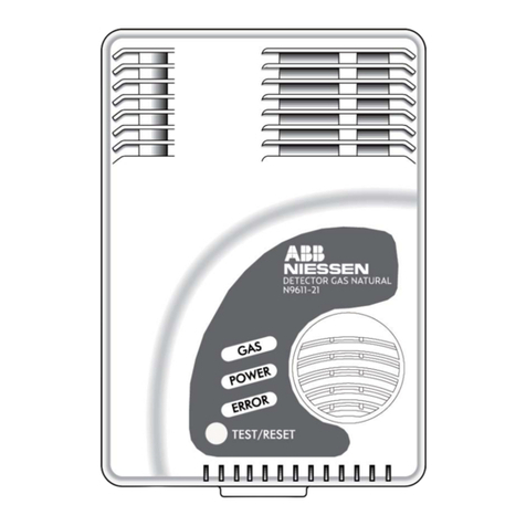
ABB N9611-21 User manual

E DETECTOR DE GAS NATURAL
GB NATURAL GAS DETECTOR
F DÉTECTEUR DE GAZ NATUREL
PT DETECTOR DE GÁS NATURAL
N9611-21
79N96112-I
Manual de Instalación y Uso
Installation and Use manual
Manuel dlnstallation et dutilisation
Manual de Instalação e Utilização
ABB
Fábrica NIESSEN
Polígono Industrial Aranguren nº 6
20180 OIARZTUN - España
Tel: 943 260101 Fax: 943 260934
E-mail: buzon.[email protected].com
www.abb.es/niessen


3
Este Detector de Gas Natural está preparado para la detección de Gas Natural.
No es operativo con Gases Licuados del Petróleo (GLP). Ha sido diseñado para
uso doméstico en un espacio ventilado. Está provisto de señales de salida,
permitiendo su uso como elemento autónomo, con una función simple de ejecución,
o como parte de una Red de elementos Domóticos.
Este Detector de Gas Natural está pensado para su funcionamiento continuo y
no debe utilizarse de forma intermitente. No es un sustituto de un detector de
humo, y no debe ser utilizado como un detector portátil para fugas de productos
de combustión. La correcta instalación y el adecuado mantenimiento de los aparatos
de combustión de gas y de sus conductos de extracción de humos debe ser una
prioridad de cara a mantener un elevado nivel seguridad en la vivienda.
El detector debe ser instalado por personal cualificado siguiendo las instrucciones
suministradas. El manual de instrucciones debe ser contemplado como parte del
producto y debe ser guardado durante la vida del mismo. Si el producto cambiara
de propietario, el manual debería traspasarse a su siguiente usuario. No manipule
el interior de la caja ya que puede causar un malfuncionamiento del detector o
recibir una descarga eléctrica.
1. I N T R O D U C C I Ó N
ES IMPORTANTE QUE LEA Y ENTIENDA ESTAS INSTRUCCIONES
ANTES DE INSTALAR EL DETECTOR DE GAS NATURAL
E

4
Figura 1. Vista General del Detector de Gas
3.1. Dónde instalar el detector
El Detector de Gas debe de ser instalado en el interior de la vivienda. Para una
correcta detección de gas debe estar situado en una pared libre de obstáculos en
el recinto donde existe un aparato de combustión de gas. En la mayoría de las
instalaciones éste será una encimera de cocina a gas o una caldera de gas. Para
el correcto funcionamiento del Detector de Gas debe estar situado en posición
vertical.
2 . D E S C R I P C I Ó N D E L P R O D U C T O
3 . I N S T R U C C I O N E S D E I N S TA L A C I Ó N
Botón TEST/RESET:
Función TEST:
hequea el funcionamiento
del detector.
Función RESET:
Permite silenciar el
zumbador y/o restablecer
la situación de reposo.
GAS (led rojo):
indicador
luminoso de
concentración
peligrosa de gas
natural.
SENSOR
ZUMBADOR
ERROR
(led amarillo):
indicador
luminoso de fallo
de funcionamiento
del detector.
POWER
(led verde):
indicador
luminoso de
correcto
funcionamiento.
E

5
El gas natural (metano en su mayor parte) es menos pesado que el aire, por lo
tanto el detector conviene que esté situado por encima de la apertura más elevada
del recinto, normalmente no a más de 30cm del techo y entre 1 a 3 metros del
aparato de combustión (Ver Figura 2). Esta ubicación debe dar buena protección
ante el monóxido de carbono flotante (originada desde una fuente caliente) en la
misma habitación. Sin embargo, si no hay ningún aparato de combustión de gas
en la misma habitación que el detector, debe instalarse a unos 2 m del suelo para
una protección óptima.
3.2. Dónde no instalar el detector
· Fuera del edificio.
· En un recinto cerrado, p.e. dentro de un armario o detrás de una cortina.
· Directamente encima de un fregadero o una cocina.
· Cerca de una puerta, ventana o un extractor.
·
En un área donde la Tª puede bajar por debajo de 5ºC o subir por encima de +40ºC.
· Donde la suciedad o el polvo puedan bloquear el sensor o parar el funcionamiento.
· En areas húmedas.
· Donde sea susceptible de ser golpeado o dañado.
3.3. Instalación y Sujeción del detector
El Detector de Gas puede ser sujetado a la superficie de la pared o a una caja
eléctrica universal de 60 mm. El detector está compuesto por una caja y un soporte
de sujeción a la pared. El soporte se libera de la caja con la ayuda de un destornillador
ejerciendo presión sobre la pestaña inferior hacia abajo hasta que la caja queda
libre. La caja puede girar con libertad para acceder a los terminales de conexión.
(Ver Figura 3).
Figura 2.
Ubicación del Detector de Gas
E

6
El detector debe ser conectado directamente y de forma permanente a la red
eléctrica de 230V conectando el cable de red en el borne de conexión situado en
el soporte, en los 2 polos del lado izquierdo del conector marcados como AC-
INPUT 230V (Ver Figura 4), dejando los 2 restantes marcados como ALARM
OUTPUT para la conexión de una válvula de corte a 230V ó señal de aviso.
Tenga en cuenta que la instalación de este tipo de válvula deberá cumplir con los
requisitos de la Norma EN 1775 para tuberías de gas en los edificios.
En caso de utilizar una caja universal empotrada en la pared siga los siguientes pasos:
1. Coloque el soporte sobre la caja de empotrar con la pestaña en la parte inferior.
2. Introduzca el cable de red de la caja empotrada a través de la ventana central
por la parte trasera del soporte.
3. Conecte el cable de red al borne de conexión. Para facilitar la operación, el borne
puede extraerse del soporte liberando las pestañas laterales con la ayuda de
un destornillador.
4. Atornille el soporte a la caja de empotrar mediante 2 tornillos.
Si el detector va instalado sobre la pared siga los siguientes pasos:
1. Conecte el cable de alimentación en el borne de conexión. (Ver Figura 4)
2. Coloque el soporte en una zona lisa de la pared con la pestaña en la parte
inferior. Asegure que tiene suficiente longitud de cable desde el soporte a la
base de enchufe antes de fijarlo a la pared.
3. Una vez seleccionada su ubicación realice 3 agujeros de Ø 5mm en las posiciones
de los tornillos.
4. Introduzca los tacos en los agujeros y atornille el soporte a la pared utilizando
los tacos y tornillos de la bolsa accesorio.
Figura 3.
Liberación de la caja sobre la base.
Figura 4.
Conexiones de cableado eléctrico.
E

7
Una vez que el soporte está sujeto a la pared
coloque la caja del detector en la misma posición
de origen. Primeramente inserte los ganchos
superiores de la caja sobre el soporte y gire
suavemente hacia la posición vertical hasta que
la pestaña inferior quede encajada en el soporte,
teniendo cuidado de la correcta conexión de los
contactos traseros de la caja en el borne de
conexión (Ver Figura 5).
Desde el momento en el que el Detector de Gas se conecta a la red eléctrica de
230V el indicador luminoso verde (marcado como POWER) comienza a parpadear
durante un periodo de calentamiento de unos 2 minutos. Una vez transcurridos,
el indicador POWER permanece iluminado indicando su correcto funcionamiento.
Durante el periodo de calentamiento el Detector no responde al gas como
consecuencia de la estabilización del sensor.
4.1. Situación de alarma
Cuando la concentración de gas natural alcanza el nivel de alarma, el Detector
avisa mediante la iluminación de los indicadores rojos (marcados como GAS para
Gas Natural, Ver Figura 1) y una llamativa alarma sonora. La salida de relé será
activada abriendo el contacto libre de tensión para señalización externa o para la
activación de una válvula de corte.
Es posible que se detecte el olor característico del gas natural a niveles inferiores
a los niveles de alarma calibrados en el detector. Esto no debe interpretarse como
fallo del detector.
4. PUESTA EN MARCHA Y FUNCIONAMIENTO
Figura 5.
Colocación de la caja sobre el soporte.
E

8
4.2. Desactivación de la alarma y restablecimiento de
la situación normal
Una vez que el gas ha desaparecido, el Detector de Gas detiene la alarma Sonora
y los pilotos de alarma pasan a un estado de parpadeo en espera del reconocimiento
de la alarma por parte del usuario. En este estado se mantiene activa la salida de
alarma. Para restablecer la situación de reposo pulse durante varios segundos el
pulsador TEST/RESET hasta escuchar un pitido. En este momento el piloto rojo
de alarma queda apagado y el relé de activación de la alarma cierra sus contactos
de salida libres de tensión. Si la salida de alarma está conectada a una electroválvula
de rearme manual ésta debe abrirse manualmente.
La función de RESET o puesta en reposo no será operativa mientras la concentración
de gas supere el nivel de alarma.
Atención: Antes de desactivar la alarma y rearmar el sistema deber
eliminar la causa del problema, o bien cerrar el paso general de gas
mediante el cierre manual de la llave de paso, ya que en el momento que
se desactiva la alarma la electrov lvula se abre y vuelve a haber gas en
la vivienda.
EN CASO DE ALARMA, LAS SIGUIENTES ACCIONES DEBEN SER TOMADAS:
- Mantenga la calma. Pulse TEST/RESET si el indicador de Gas Natural está
iluminado.
- Apague cualquier llama. No fume ni encienda ni apague ningún interruptor
eléctrico.
- Abra las puertas y ventanas para evacuar el gas.
-Cierre la llave suministro de gas y todos los electrodomésticos de
combustión. No utilice ningún electrodoméstico hasta que haya sido
inspeccionado por un experto.
- Si alguien sufre de los posibles efectos de envenenamiento por Gas Natural
(p.e. dolor de cabeza, mareos, nausea o vómitos) consiga ayuda médica y
avise de la sospecha de envenenamiento por Gas Natural.
- En caso de que la alarma persista, y la causa de la fuga no sea evidente o
no pueda ser reparada, evacue el local o la vivienda INMEDIATAMENTE
dejando las puertas y ventanas abiertas. Notifique el hecho al distribuidor
o a un servicio de emergencia de gas.
E

9
4.3. Función Autotest / Silenciamiento de la Alarma
Mediante la pulsación de TEST/RESET durante el funcionamiento normal (después
del precalentamiento) se inicia el autotest. Los indicadores se iluminan
secuencialmente y la alarma sonora es activada durante 1 segundo. Todos los
indicadores permanecen encendidos hasta que se pulse una segunda vez, tras lo
cual el piloto POWER permanece iluminado indicando el funcionamiento normal.
Si se pulsa una segunda vez manteniendo pulsado TEST/RESET durante 10
segundos se testea la apertura de los contactos del relé. Los indicadores de alarma
permanecen encendidos y el relé abre sus contactos. Una vez comprobado el
funcionamiento del test de alarma, el sistema puede ponerse en reposo pulsando
brevemente el pulsador TEST/RESET.
Es recomendable realizar este autotest una vez a la semana para confirmar su
correcto funcionamiento. Si la respuesta del Detector es diferente de la descrita
anteriormente, no funciona correctamente. REEMPLACELO INMEDIATAMENTE.
4.4. Sensor
Un fiable y preciso sensor semiconductor monitoriza constantemente el nivel de
Gas Natural en el aire. Este sistema de sensor informa a un microprocesador
continuamente y con precisión de la presencia de tan sólo pocas partes por millón
(ppm) de Gas Natural. El microprocesador además de medir el nivel de gas en el
aire, testea el correcto funcionamiento del sensor, circuitos electrónicos y fuente
de alimentación.
Cuando el microprocesador diagnostica un problema durante su regular testeo, el
indicador amarillo (marcado como ERROR) se ilumina y el detector interrumpe su
funcionamiento. Si esto ocurre su detector no le está ofreciendo protección
REEMPLACELO INMEDIATAMENTE.
4. . Mantenimiento
Para limpiar la caja utilice un paño húmedo. No utilice productos de limpieza, lejía
o ceras. Evite utilizar los siguientes productos cerca del Detector de Gas. Pueden
afectar a la fiabilidad y estabilidad a corto y largo plazo del sensor:
· Sprays aerosoles.
· Alcoholes
· Agentes limpiadores y disolventes.
· Gas proveniente de encendedores de tabaco.
· Cigarrillos y humo.
E

10
5 . E S P E C I F I C A C I O N E S
.1. Características principales
El Detector de Gas Natural N9611.21 tiene las siguientes especificaciones de
funcionamiento:
Cabe remarcar que la válvula de corte debe ser del tipo normalmente cerrada
(abierta cuando es alimentada eléctricamente) y que es esencial su reapertura
manual, para cumplir con la directiva de aparatos de gas (90/396/EEC) y regulaciones
de aparatos de gas (Seguridad) de 1992.
La válvula de corte de gas al ser del tipo normalmente cerrada, se cerrará
automáticamente, cortando el paso de gas ante una eventual caída de tensión de
red de suministro eléctrico, siendo necesario su reapertura manual posterior,
cuando se restablezca la tensión de red de suministro eléctrico, para permitir de
nuevo el paso de gas natural a través de la misma.
· Rango de Tensión de Alimentación: 1 5 a 264 Vac
· Frecuencia de Alimentación: 50-60 Hz
· Máxima Potencia Consumida: 1,5W
· Salida de alarma: Contacto libre de tensión
(Normalmente cerrado) (Max.277 V AC/ 3A)
· Rango de Temperatura de funcionamiento: -5 a 40 ºC
· Rango de Humedad de funcionamiento: 30 a 90 % RH
· Nivel sonoro: 5 dB(A) a 3 m.
· Dimensiones : 145mm(Al)x100mm(An)x55mm(Pr)
· Peso: 200 gr.
E

11
.2. Funcionamiento del Detector de Gas
El funcionamiento del detector está diseñado para cumplir la norma UNE EN
50194:2000 para Gas Natural usando los criterios siguientes:
· Alarma Gas Natural: 9% LIE (Límite Inferior de Explosividad) en 20 segs.
Este Detector de Gas Natural está calibrado en fábrica y no necesita recalibración.
Sin embargo, para optima fiabilidad, debe ser remplazado no más tarde de
transcurridos 5 años desde de la fecha de instalación, como debe ser indicado en
la etiqueta incluida en la caja.
ATENCIÓN: POSIBLE PELIGRO DE DESCARGA ELÉCTRICA O MAL
FUNCIONAMIENTO SI EL APARATO ES MANIPULADO.
6. Garantía
Todos los aparatos fabricados o distribuidos por Asea Brown Boveri S. A. Fábrica
Niessen están realizados de acuerdo a la más moderna tecnología.
La fábrica NIESSEN garantiza sus artículos, dentro de las condiciones generales
de suministro, siempre que se trate de un defecto de fabricación. En este caso le
rogamos remita el aparato defectuoso al distribuidor donde lo adquirió, acompañado
del presente certificado de garantía
Cobertura
La presente garantía se aplicará a aquellos artículos que presenten un defecto de
fabricación. No se aplicará por tanto a los artículos que presenten daños como
consecuencia de no haber seguido correctamente las instrucciones de montaje o
cuando la instalación ha sido realizada por personal no especializado.
Así mismo quedan excluidos los daños ocasionados por uso indebido del aparato
y averías producidas en el transporte.
Vigencia
La duración de esta garantía contempla 24 meses, contados a partir de la fecha
de adquisición del aparato.
- Fecha de Adquisición:
- Sello y Firma del distribuidor:
Importante: Asegúrese de que el presente certificado de garantía está debidamente
cumplimentado por el distribuidor.
E


13
This Natural Gas Detector is prepared to detect Natural Gas. It is not operative
with Liquefied Petroleum Gas (GLP). It has been designed for domestic use in
ventilated space. It is equipped with output signals, allowing its use as autonomous
element, with a simple execution function, or as part of Network of Domotics
elements.
This Natural Gas Detector is designed for continuous operation and it should not
be used in an intermittent way. It is not a substitute of a smoke detector and it
should not be used as a portable detector for combustion products leakage. The
correct installation and the appropriate maintenance of the gas combustion
equipment and smoke extraction ducts should be a priority in order to maintain
a high level of security in the house.
The detector should be installed by qualified personnel following the provided
instructions. The instructions manual should be considered as part of the product
and be kept during its life. If the product changes proprietor, the manual should
be passed to the next user. Do not operate the box inside because you can cause
a malfunction of the detector or receive an electrical discharge.
1. INTRODUCTION
IT IS IMPORTANT THAT YOU READ AND UNDERSTAND THESE INSTRUCTIONS
BEFORE INSTALLING THE NATURAL GAS DETECTOR
GB

14
Figure 1. General Layout of the Gas Detector
3.1. Where to install the detector
The Gas Detector should be installed inside the house. For correct gas detection,
it should be located in a wall free of obstacles in the enclosure where there is gas
combustion equipment. Most installations are located on a gas kitchen worktop
or on a gas boiler. For the correct operation of the Gas Detector it should be placed
in a vertical position.
2 . DESCRIPTION OF THE PRODUCT
3 . INSTALLATION INSTRUCTIONS
TEST/RESET Button: TEST
> Function: hecks up the
detector operation.
> RESET Function: Allows
silencing the buzzer and/or
restore the sleep mode
GAS (red led):
Light indicator of
natural gas danger
concentration.
SENSOR
BUZZER
ERROR (yellow
led): Light
indicator of
detector operation
failure
POWER (green
led): Light
indicator of
correct operation.
GB

15
The natural gas (mostly methane) is less heavy than the air, therefore it is
convenient that the detector is placed above the highest opening of the enclosure,
normally no more than 30 cm from roof and between 1 and 3 meters of the
combustion equipment (see Figure 2). This location must provide good protection
to floating carbon monoxide (originated from a hot source) in the same room.
Nevertheless, if there is no gas combustion equipment in the same room of the
detector, it should be installed at around 2 m from the floor for an optimum
protection.
3.2. Where not to install the detector
· Outside the building.
· In a closed enclosure, e.g. inside a wardrobe or behind a curtain.
· Directly on top of a sink or a kitchen.
· Next to a door, window or extractor.
· In an area where the temperature can fall below -5ºC or raise above -40ºC.
· Where dirt or dust can block the sensor or stop the operation.
· In humid areas.
· Where susceptible of being beaten or damaged.
3.3. Installation and Fixing of the detector
The Gas Detector can be fixed to the wall surface or to a 60mm universal electric
box. The detector is composed by a box and a wall fixing support. The support
is released from the box with the help of a screwdriver, pressing on the lower
flange down until the box is free. The box can spin freely to accede to the connection
terminals. (See Figure 3).
Figure 2.
Gas Detector Location
GB

16
The detector should be connected directly and permanently to the 230V electric
network, connecting the network cable in the connection terminal placed in the
support, in the 2 left poles of the connector marked as "AC-INPUT 230V" (See
Figure 4), leaving the 2 others marked as "ALARM OUTPUT" for the connection
of a cutoff valve at 230V or notification signal.
You should take into account that the installation of this type of valve should
comply with the requirements of Standard EN 1775 for buildings gas pipes.
In case of using a flush-mounted universal box, follow the next steps:
1. Place the support over the flush-mounted box with the flange in the lower
part.
2. Introduce the flush-mounted box network cable through the central window,
by the back of the support.
3. Connect the connection terminal network cable. To facilitate the operation, the
terminal can be extracted from the support releasing the lateral flanges with
the help of a screwdriver.
4. Fasten the support to the flush-mounting box with two screws.
If the detector is installed on the wall, follow the next steps:
1. Connect the power supply cable in the connection terminal. (See Figure 4)
2. Place the support in a smooth area of the wall with the flange in the lower part.
Make sure that the cable is long enough from the support to the plug base
before fixing it to the wall.
3. Once the location is selected make 3 holes of 5mm in the screws position.
4. Introduce the rawplugs in the holes and screw the support to the wall using
the rawplugs and screws of the accessories bag.
Figure 3.
Releasing of box on base.
Figure 4.
Electrical cabling connections
GB

17
Once the support is fixed to the wall, place the
detector box in the same origin position. Firstly
insert the upper hooks of the box on the support
and turn gently toward the vertical position until
the bottom flange is fitted in the support, being
careful that the box rear contacts are correctly
connected in the connection terminal (See Figure
5).
From the moment the Gas Detector is connected to the electric network of 230V
the green light indicator (marked as POWER) starts blinking during a heating
period of around 2 minutes. After two minutes, the POWER indicator remains
lighted indicating its correct operation. During the heating period the Detector
does not respond to gas as a consequence of the sensor stabilization.
4.1. Situation of alarm
When the natural gas concentration reaches the level of alarm, the Detector notifies
using the red lights indicators (marked as GAS for Natural Gas, See Figure 1) and
an acoustic alarm. The relay output will be activated opening the voltage-free
contact for external signalling or for the cutoff valve activation.
It is possible to detect the characteristic odour of natural gas at lower levels to
the alarm levels measured in the detector. This should not be interpreted as the
detector failure.
4. START UP AND OPERATION
Figure 5.
Placing the box on the support
GB

18
4.2. Deactivation of the alarm and normal situation
restoration
Once the gas is gone, the gas detector stops the acoustic alarm and the alarm
lights go to a blinking state waiting the recognition of the alarm by the user. In
this state the alarm output remains active. To restore the sleep situation press
during several seconds the push button TEST/RESET until a beep tone is listened.
In this moment the red light of the alarm turns off and the alarm activation relay
close its voltage-free output contacts. If the alarm output is connected to an
electric valve of manual rearming this should be opened manually.
The function RESET or go to sleep will not be operative while the gas concentration
exceed the alarm level.
Warning: Before deactivating the alarm and rearming the system, the
cause of the problem should be eliminated, or block the general gas way
by the manual closing of the stopcock, since in the moment the alarm
is deactivated the electric valve opens and there is again gas in the house.
IN CASE OF ALARM, THE FOLLOWING ACTIONS SHOULD BE TAKEN:
- Keep calm. Press TEST/RESET if the Natural Gas indicator is lighted.
- Extinguish the flame. Do not smoke nor turn on or off any electric switch.
- Open doors and windows to exhaust gas.
- Close the gas supply key and all the combustion electrical appliances. Do
not use any electrical appliance until it has been examined by a qualified
person.
- If somebody suffers of possible Natural Gas poisoning effects (headaches,
sickness, nausea or vomit) obtain medical assistance and notify the suspicion
of Natural Gas poisoning.
- In case the alarm continuous, and the leak cause is not evident or cannot
be repaired, evacuate the room or the house IMMEDIATELY leaving doors
and windows open. Notify the fact to the distributor or to a gas emergency
service.
GB

19
4.3. Self test Function / Silence of the Alarm
By pressing TEST/RESET during the normal operation (after the preheating) the
self test initiates. The indicators are lit sequentially and the acoustic alarm is
activated during 1 second. All indicators remain lit until pressing for a second time,
after which the pilot POWER remains lit indicating the normal operation. If the
TEST/RESET button is pressed for a second time and pressing is maintained
during 10 seconds, the relay contacts opening function is tested. The alarm
indicators remain lit and the relay opens its contacts. Once the alarm test operation
is checked, the system can be put in sleep mode pressing shortly the TEST/RESET
push button.
It is recommended to do the self test once a week to confirm its correct operation.
If the Detector answer is different from the one previously described, it is not
working correctly. REPLACE IT IMMEDIATELY.
4.4. Sensor
A reliable and precise sensor semiconductor monitors constantly the Natural Gas
level in the air. This sensor system informs a microprocessor, continuously and
precisely, the presence of only few parts per million of Natural Gas. The
microprocessor apart from measuring the gas level in the air, tests the correct
operation of the sensor, electronic circuits and power supply.
When the microprocessor diagnoses a problem during its regular testing, the
yellow indicator (marked as ERROR) is lit and the detector stops its operation.
If this happens, your detector is not giving you protection, REPLACE IT
IMMEDIATELY.
4. . Maintenance
To clean the box, use a wet cloth. Do not use cleaning products, lye or wax. Avoid
using the following products next to the Gas Detector. They can affect the sensor's
reliability and stability at short and long term:
- Aerosol sprays.
- Alcohols.
- Cleaning and dissolver agents.
- Gas coming from lighters.
- Cigarettes and smoke.
GB

20
5 . SPECIFICATIONS
.1. Main characteristics
The Natural Gas Detector N9611.21 presents the following operation specifications:
It should be noticed that the cutoff valve must be of the type normally closed
(opened when it is electrically supplied) and that it is essential its manual reopening,
to meet the gas equipment regulations (90/396/EEC) and (Safety) of 1992.
The cutoff valve, as it is of type normally closed, will close automatically, cutting
the gas flow before a possible electric supply network voltage drop, being necessary
its later manual reopening, when the electric supply network voltage is restored,
to allow again the natural gas flow through it.
· Power supply tension range 1 5 to 264 Vac
· Power supply frequency 50-60 Hz
· Maximum Power Consumed 1,5W
· Alarm output Contact free of tension
(Normally close) (Max. 227 V AC/3A)
· Operation temperature range -5 to 40ºC
· Operation humidity range 30 to 90% RH
· Acoustic level 5 dB(A) to 3 m.
· Dimensions 145mm (AI)x100mm(An)x55mm(Pr)
· Weight 200 gr.
GB
Other manuals for N9611-21
1
Table of contents
Languages:
Other ABB Gas Detector manuals
Popular Gas Detector manuals by other brands

Honeywell
Honeywell BW GasAlertQuattro user guide

Vemer
Vemer RGG WAVE user manual

Honeywell
Honeywell BW GasAlertMicroClip XT user manual

AIR SYSTEMS
AIR SYSTEMS CO-91 Series Calibration guide

Critical Environment Technologies
Critical Environment Technologies CGAS-A Series Installation & operation manual

Compur Monitors
Compur Monitors Tracer manual