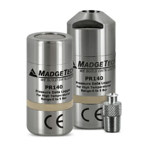
Hanwell 4000 Series User manual

hanwell.com
IM5990
4000 Series Sensor
Units
User Guide

Intentionally Left Blank

4000 Series Sensor Units
User Guide
IM5990-8 Page 1 of 23 hanwell.com
Document History
Document Number: IM5990
Issue
No. Issue Date Changes By
1 1 June 2018 First Issue IR
2 7 November 2018 Additions to Section 2.4 Compliance IR
3 13 November 2019 Addition of Section 3.1 - Connecting Sensor
Units to External Probes IR
4 30 January 2020 Amendments to take account of the
introduction of EMS Version 1.0.10 IR
5 3 December 2020
Alarm Corrections; remove obsolete text
remote Management tools text; change CR2 to
CR3.
CRB
6 10 December 2020 Addition of information on Durable Units IR
7 22 February 2021 Minor change to terminology IR
8 4 March 2021 Addition of reference to UKCA marking on
page 5 IR

4000 Series Sensor Units
User Guide
hanwell.com Page 2 of 23 IM5990-8
Contents
1Introduction......................................................................................................................... 3
1.1 Pre-requisites .....................................................................................................................................3
2The 4000 Series Sensor Unit ........................................................................................... 4
2.1 Sensor Unit Battery...........................................................................................................................5
2.2 Mounting the Sensor Unit ...............................................................................................................5
2.3 Radio Testing Dongle ......................................................................................................................5
2.4 Compliance.........................................................................................................................................5
2.5 Start-up Messages ............................................................................................................................6
2.6 Cleaning the Sensor Unit ................................................................................................................6
3Setting up 4000 Series Sensor Units .............................................................................. 7
3.1 Connecting Sensor Units to an External Probe ........................................................................ 7
3.2 Testing the Sensor Unit...................................................................................................................8
3.3 Entering a 4000 Series Sensor Unit’s Calibration Settings into EMS.................................8
3.3.1 Setting Alarms ............................................................................................................................ 15
3.4 Synchronising Sensor Units ......................................................................................................... 16
3.4.1 Alarms on Sensor LCD Display.............................................................................................. 19
3.5 Merging Collected Data ............................................................................................................... 20
4Contact Hanwell Solutions..............................................................................................23

4000 Series Sensor Units
User Guide
IM5990-8 Page 3 of 23 hanwell.com
1Introduction
This Document details how to configure the RL4000 and ML4000 Series Sensor Units (including
Durable Units) from Hanwell Solutions Ltd for use in conjunction with the EMS application.
•Durable Units (-DU) function in exactly the same way as other 4000 Series Sensor Units, but
have a higher IP Rating.
It also details the additional functions, such as Calibration.
The 4000 Series Sensor Units are, essentially, transmitters with one, two or three data channels.
The Units take data received from attached sensors/probes and transmit it to the Hanwell EMS
System at defined Transmission Intervals, either directly or via an SR2 Controller.
•The sensor(s)/probe(s) themselves can be mounted directly onto the 4000 Series Sensor
Unit’s case or on a lead connected to the Unit.
•The current Data Values, battery voltage/predicted battery life and (optionally) the Alarm
Status are displayed on the Sensor Units’ LCD screens.
•The Sensor Units are configured with the EMS software via a USB connection.
•The Sensor Units hold their Calibration Data in their on-board memory and can also be
programmed with the High/Low Alarm Values set on the EMS host PC/Server.
•Mark 8 and above 4000 Series Sensor Units can also log data on-board in their internal
memory.
1.1 Pre-requisites
You will need the following to enable communication between EMS and a 4000 Series Sensor Unit:
•Y055 USB lead.
•EMS application installed on a PC/Server.
•EMS Remote Management Tools

4000 Series Sensor Units
User Guide
hanwell.com Page 4 of 23 IM5990-8
2The 4000 Series Sensor Unit
The illustrations below represent typical 4000 Series Sensor Units fitted with probes.
Figure 1 – Typical 4000 Sensor Units
Durable Unit
Figure 2 – Typical 4000 Series Sensor Unit - Schematic
Note: The actual design will vary depending on the probes you have installed.

4000 Series Sensor Units
User Guide
IM5990-8 Page 5 of 23 hanwell.com
2.1 Sensor Unit Battery
Most variants of the 4000 Series Sensor Units are powered by a 3.6V AA Lithium battery.
•The battery life is dependent on the Transmit Interval set.
•If a batch of Sensor Units have been set up at the same time, we recommend changing the
batteries of all of the batch simultaneously.
•Replacement battery Hanwell Part Number: 88706.
Caution: Do Not Fit Standard Alkaline AA Batteries.
2.2 Mounting the Sensor Unit
A wall-mounting bracket is available for the 4000 Series Sensor Units (Code: Y119). It comprises a
metal strip which is fitted to the wall.
•To mount a 4000 Series Sensor Unit on the bracket, line up the slots on the back of the Unit
with the tabs on the bracket and click the Unit into place.
•To remove 4000 Series Sensor Unit from the bracket, gently press the tag at the bottom of
the Unit’s case towards the wall, using a small screwdriver or similar, and lift the Unit free.
Durable Units
Wall-mounting brackets are also available for the RL4000-DU Series Sensors
Part Numbers:
Y549 (ML4109- DU)
Y550 (All other RL4000-DU Series units).
2.3 Radio Testing Dongle
This is an optional plug-in device (Code: Y058).
When connected to a 4000 Series Sensor Unit USB socket, it overrides the Unit’s configured
Transmit Interval and forces the Unit to send a transmission every five seconds.
2.4 Compliance
4000 Series Sensor Units have been designed to comply with all relevant RoHS and WEEE EU
Directives and carry CE and UKCA marking.
Hereby, Hanwell Solutions Ltd declares that the RE type 12K5 FIDBN is in compliance with RED
2014/53/EU.
The full text of the EU Declaration of Conformity is available at the following internet address:
https://hanwell.com/download-category/declarations-of-conformity

4000 Series Sensor Units
User Guide
hanwell.com Page 6 of 23 IM5990-8
2.5 Start-up Messages
Mark 8 and above versions of the 4000 Series Sensor Units will show the following sequence on
their LCD displays on power up:
•All display segments will flash twice.
•A Serial Number is displayed on two lines.
•A Frequency Code* is displayed on the top line of the display and a Transmission ID on the
lower line.
* Earlier versions only show the Transmission ID.
The Frequency Code indicates the Synthesised Frequency Setting. It will be 0 for a connected
module, otherwise contact Hanwell Solutions for an up-to-date list if there is any doubt.
The Frequency is also marked on the instrument labelling.
The full start up sequence will only occur after the battery has been disconnected for a minute or
more or the device is given a Hardware Reset by shorting the pads visible beside the battery.
2.6 Cleaning the Sensor Unit
The 4000 Series Sensor Unitsare cased in ABS plastic and can be cleaned using a damp, non-
abrasive cloth.
Caution: Do NOT immerse the Sensor Unit in water!

4000 Series Sensor Units
User Guide
IM5990-8 Page 7 of 23 hanwell.com
3Setting up 4000 Series Sensor Units
For information on entering 4000 Series Sensor Units’ details into EMS, please refer to the EMS
Online User Guide, in particular the section System Configuration - Sensors:
http://www.help.emsprocloud.com/index.html?system-configuration-sensors.html
•4000 Series Sensor Units should be added to EMS using the appropriate type as indicated on
the Box Insert/Certificate.
3.1 Connecting Sensor Units to an External Probe
Figure 3
Sensor Unit with Wiring for External Probe.
Sensor Units supplied with wiring for external probes (see example in Figure 3 above) should be
connected to them as follows:
Channel No. +ve -ve
1 Green Black
2 Red White
3 Yellow Blue
Note: Any unused pairs of wires should be twisted together.

4000 Series Sensor Units
User Guide
hanwell.com Page 8 of 23 IM5990-8
3.2 Testing the Sensor Unit
Before putting a 4000 Series Sensor Unit in its intended monitoring location, we recommend testing
its operation after entering its details into EMS:
•Connect a Radio Testing Dongle (Code: Y058), if you have one, to the USB socket of the
Sensor Unit to speed the test.
1. Check that a signal is being received on the EMS System from the Sensor Unit.
•If you are using a CR3 then you will see the message: ‘last signal #’(where # is the ID
Number set) displayed on the CR3’s LCD.
•If you are using a SR2 then you will see both the ID Number and its signal strength on
the SR2’s LCD.
2. Check that the correct values are displayed on the EMS User Interface on the host PC/Server.
3. Site the Sensor Unit in its intended monitoring location and confirm that signals are still being
reliably received.
3.3 Entering a 4000 Series Sensor Unit’s Calibration Settings into EMS
In EMS:
1. Select Edit Mode from the main View Data menu. See Figure 4 below:
Figure 4
•The Edit Mode window is displayed. See Figure 5 below:

4000 Series Sensor Units
User Guide
IM5990-8 Page 9 of 23 hanwell.com
Figure 5
•By default, the Edit Mode window for the Zone at the top of the left-hand menu is
displayed.
•To display another Zone's Edit Mode window, click on the entry for the required Zone in
the left-hand menu. For an example, see Figure 6 below:
Figure 6

4000 Series Sensor Units
User Guide
hanwell.com Page 10 of 23 IM5990-8
Note: Edit Mode is only available if you have the correct access Permissions.
If you do not have the correct access Permissions the following message window will be
displayed. See Figure 7 below:
Figure 7
2. Either:
i. In the left-hand list of the Zone's Edit Mode window, click on the small 'arrow' symbol to
display a list of the Sensor Units associated with the Zone. See Figure 8 below:
Figure 8
ii. In the left-hand list, click on the required 4000 Series Sensor Unit’s icon:
Or:
In the table in the Zone's Edit Mode window, click on the required 4000 Series Sensor Unit’s
name in the Sensor Name column. See Figure 9 below:

4000 Series Sensor Units
User Guide
hanwell.com Page 12 of 23 IM5990-8
Figure 10
3. Click the on the Calibration field to expand the Calibration pane for the selected 4000 Series
Sensor Unit.
•The Calibration pane will display a separate tab for each channel/probe associated with
the selected 4000 Series Sensor Unit.
See Figure 11 below:

4000 Series Sensor Units
User Guide
IM5990-8 Page 13 of 23 hanwell.com
Figure 11
4. Click on each tab representing the sensor(s)/probe(s) to be calibrated and:
i. Enter the date that the next Calibration is due into the Next Calibration Due Date field,
in the format:
YYYY-MM-DD
∗If the Sensor Unit has just been added to the System, you will notice that the
default date on the form will be one year from the date that the Sensor Unit was
added.
∗The normal calibration period is one year.
∗A good rule of thumb would be 12 months for environments that are either
contaminated or have consistently high operating humidities.
Where the environments are uncontaminated and average humidities are mid-
range, then every 24 months would be acceptable.

4000 Series Sensor Units
User Guide
hanwell.com Page 14 of 23 IM5990-8
ii. Enter or edit any other Calibration parameter values as required.
∗Where a particular sensor/probe’s parameters include values for Offset and Gain,
these will be listed on the sensor/probe’s Box Insert.
∗For more detailed information on Sensor Unit calibration parameters, please refer
to the Online Manual:
http://www.help.emsprocloud.com/index.html?calibration-general.html
5. When you are happy with the new date select Save.
•Click on the Back button to cancel any changes to the Next Calibration Due Date.
If the Update has been successful, you will be returned to Edit Mode window and the following
message will be displayed. See example in
Figure 12 below:
Figure 12
6. Repeat Steps 2 -5 for all required 4000 Series Sensor Units.

4000 Series Sensor Units
User Guide
IM5990-8 Page 15 of 23 hanwell.com
Note: Should you wish to carry out your own calibration of a sensor/probe, please refer to both
the EMS Online User Guide:
http://www.help.emsprocloud.com/index.html?calibration-management-tools.html
and the following links which are also listed on the Box Insert:
http://pd.hanwell.com/Cal-linear-sensor.xls
http://pd.hanwell.com/Cal-linear-sensor.zip
3.3.1 Setting Alarms
To set Alarm Parameters and Levels, refer to the following section in the EMS Online User Guide:
http://www.help.emsprocloud.com/index.html?levels.html

4000 Series Sensor Units
User Guide
hanwell.com Page 16 of 23 IM5990-8
3.4 Synchronising Sensor Units
The Synchronise process takes data from a connected USB device and updates its Serial Number,
and Calibration settings in the EMS Database; as well as setting the Physical Transmit ID of the
device from the EMS Database.
Note: If the Physical Transmit ID listed in the Unit does not match the ID of the Sensor that you
are trying to synchronise with, then the ID listed in the Unit’s memory will change to what is
set on the Sensor Unit you are synchronising with.
•Synchronising Sensor Units facilitates efficient communication between the Sensor Units and
EMS.
•Even if a Sensor Unit is already running on EMS, it is strongly recommended to carry out
Synchronisation to set a faster transmit rate when calibrating.
To Synchronise a Sensor Unit:
1. Ensure that the Sensor Unit is connected to the PC/Server running EMS via the supplied Y055
USB lead.
2. Open the EMS Remote Management Tools application.
•EMS Remote Management Tools provide:
∗A physical link to the database and would be used when it is possible to connect
the Sensor Unit directly to the PC with EMS installed via the Y055 USB lead.
∗An HTTP link to data in the EMS database, allowing you to synchronise a Sensor
Unit when using EMS installed on a Virtual Machine (VM).
Refer to the Synchronising Sensors section of the EMS Online User Guide:
http://www.help.emsprocloud.com/index.html?calibration-management-
tools.html#synchronisingsensors
3. Select the required Sensor Unit from the EMS Remote Management Tools' EMS Management
window. See Figure 13 below:

4000 Series Sensor Units
User Guide
hanwell.com Page 18 of 23 IM5990-8
Figure 15
Note: The Sensor Unit selected must match the physical device or the program will not
complete.
5. Select the required Transmit (TX) interval from the Transmit interval drop-down list (60
seconds is recommended for Calibration).
•The EMS Synchronise USB Sensor Vx.x window completes loading and all of the
window’s fields are populated.
6. Click the Synchronise button and follow the instructions given until it reports that the
Synchronisation is complete.
•The Sensor Unit’s display should now show the same value as displayed in EMS.
7. Close the window to finish Synchronisation and update the EMS database.
8. Repeat Steps 1 - 8 for all Sensor Units to be added.
Refer to the following section in the Online EMS User Guide for information on Viewing Sensor
Data:
http://www.help.emsprocloud.com/index.html?viewing-data2.html
Table of contents


