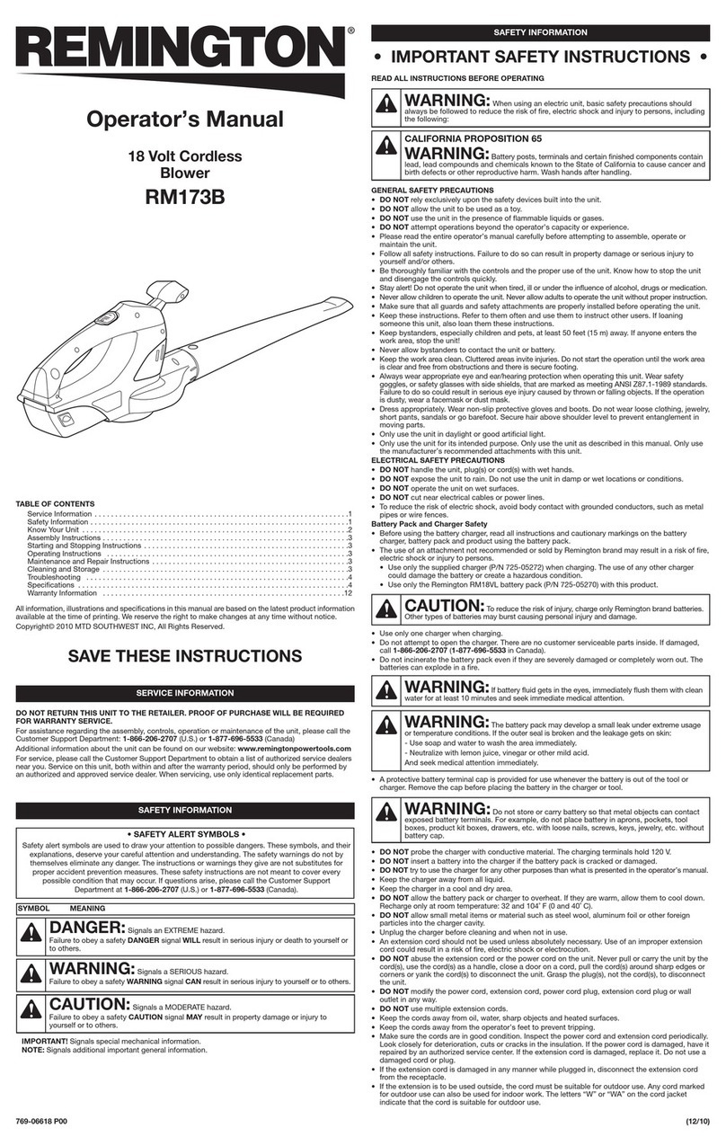
Haotian XD4A User manual

CONTENTS
Product I
11
troduction-------------------------------------------------------
.------
1
Sa
fely Considerut
ion
s ------------------------------------------------------------ 1
Main Suucture--------------------------------------------------------------------- I
Operating Procedures and Precautions----------------------------------------- 2
Care and
Mai
n
Icnan
cc-----------------------------.--------.--------------------- 2
Main Troubles
and
How
10 Solve Them --------------------------------------- 3
IncIuded Accessories ------------------------------------------------------------- 3
Tech
ni
ea
I Parameters ------------------------------------------------------------- 4
Ex.plosion
Vi
ews-------------------------------------------------------------------
5-9
•
•
Product Introduction
Welcome to buy and use XD4A Sweeper-Drier. Thi.s machine features
in
ea~y
operation, safe use lind good cleaning effect, suitable for cleaning
of
the
~nl:lll
and
medium-sL~ed
grounds
in
office building. hotel, warehollse and square.
Safety Considerations
I.This machine
is
not suitable for cleaning
of
the carpel.
2.1n the
eventlhal
the recharger
or
electric cable
is
damaged, please immediately
contact the manuf:lclUrer
or
its authoriLed service center.
3.Never mix different types
of
cleaning agent.;;; otherwise
tox.i
c
gas
will
he
generated.
4.Never use
thi.;;
machine
in
explosive environment.
S.Never
u.;;e
thi.;;
machine for suction
of
inflammable liquids.
6.Never
usc the acid
liquid~
that can
damage
this
m:lI.:hine.
7.Make
sure to shul down this machine and disconnect the battery before
maintenance.
8.Never
clean this machine with high-pressure
jet
waler
or
corrosive subslances.
9.1n case Ihal the machine is
ca
u
ght
to lire, please immedialely use powder
extinguisher. Never
use
water. Main Structure
The main structure
of
XD4A
multifunction
:11
bru.;;hing machine is liS shown
in
Fig. I:
1.
Operating Handle
_1
2.
Right switch
3.
Safety
loeb.
4.
Angle adjustment pull handle
c----.-
6 5. Sewage pipe
6.
Air
intake pipe
7. Sewage tank
H.
Clear
water tank
9.
Rear wheel
10
.
SUClion
head
II.
15
....
ground scrubber
_-1
1
1
•

Operating Instructions
I.
Unpad the m
achllIC
and
t
ake
It
out
from
the
base
plme.
Place
dIC
nl:lChm
e
on
ground
and
moum
cleaning
sc
rubber
2.
As
sIlo"'n
In
h
g.
I. adJuslthe
angle
adJustmenl
pull
handle
10
90
- 1
20·
1l1ocn
.
re
l
oo~'e
the
Clear
water
tmk.
Unlock
the
1
.....
0 c
lnmiX
on
lhe
hanery
compartnx:m
at
the
back
of
machine
and
OOIlncctlh
e
banery
to
a
find
socket.
3.
In ~
tallthe
~Incry
compartnlClll
OO~"Cr
and
clear
water
tank.
Add
an
approp
ri
ate
qu.ant
it)'
ofcl
eaoo;er
wlutioo.
4.
I
nstall
lhe
.o;c
wage
tank"
to
thc
hook
on
thc
aluminum
pipe
of
opcmting
hand
l
e.
and.ooonect
the
,uction
pipe
and
1iCw~gc
pipe
to
the
.o;c
wage
t
an
k.
6.
Put
down
t
he
.
welion
h
ead
UP/JX)WN
handle
on
the
back
of
m:lch
i
ne
(Fig
.
3).
In
t
h
i
~
cao;c,
the
suCl
i
on
head
ha~
been
nat
l
)'
placed
on
the
ground.
Pull
Ihe
angle
ooJu'lnl<.:nl
h~ndle
to
adju
st
operatmg
hand
le
10
tile
heighl
dc"red
b)'
the
opcnuor.
Then,
relea.o;e
the
handle.
6.
Pullhoe
main
scrubber
sw
itch
(I).
pumping
switch
(2)
and
.-.oleoold
valve
swi
tch
(3)
011
the
panel
or
operoling
handle
10
"ON"
position.
Owxk
if
the
signal
lamp
is
bright
(green).
11Jcon.
pu~
the
safety
lock"
on
opcroting
handle
10
celller.
and
clo!;e
l
he
hand-operatcd
sw
itch.
"'"
I
ha
t
lhe:
machllle
will
Slart
to
wort;
.
Fi!!
.2
•
Fig.)
Waler
flead
lW/OOWN
S"';ICh
Care
and
Maintenance
I
MJIn
\o:ruhber
,
...
,td,
1.Solen<>ioj
".I.'c
I""k'h
To extend the
~rv
i
ee
life
of
Ihe
machinc and enable the machine to work under lhe
he'l
cffect.
it
is
sugge~te
d
to do the
fo
llowing aftcr each usc:
I.
u~
clear waler
10
wa~h
the suction head elean and wipe with dry cI\llh.
2.
R
emow
Ihe
scwage lank and use clear water to wash
it
ckan.
AI
the
,al11C
time. use water
10
rinsc
Ihc
suction pi
pe
clean.
3.
Th
is
machine
ca
nnot
be
wash
tli
rectly with water, hut
be
wiped with
~ertli·dry
clot
h,
thus
10
ensurc thai no wat
er
wi
ll
enter into
the
machine. Otherwise. the electric
part~
of
the machine
wi
ll
be
burn
t.
4. when the machine
is
to
be
put
long out
of
~
rvice. the battery
~hall
otherwise the
<.crv
icc
li
fe
of
the battery will be reduced.
2
be
regularly recharged;
•
•
•
Main Troubles
and
How to Sol
ve
Them
No powcrsu
ppl
y
No suction force
or
the
suction forcc is low
The scrublx:r motor
cannot
ro
late after
it
is
energized
The powcr
soc
i..
cl
h.
not prope
rl
y Connect t
conn
ect(.-d
properly
The ma
in
!>Cru
bber
~w
it
c h
is n
O(
Ch
ec
k and put
it
to ON
10
ON
~
,
'"-----------fJ
~~---,-,,___,,____
and wash the suc
ti
on
The suction pipe is
hl
ocked
The sewage tank Co\cr is not
installed properly
The pipe
co
nn
ec
tion is not tight
The suction carbon brush
is
worn
The hand-operated power sw
it
ch
is
burnt
The
sc
ruhber motor
is
burnt
TI
le
ci
rcui t board
is
fai
lcd
TIll!
carbon bru
sh
or
motor
is
p'pe
Rei
nstall
an
d seal the
~w
a
ge
tank cover prope
rl
y
Check and repair
Replace the power sw
it
ch
Repair
or
re
place the
mOior
Rcpa
ir
or
re
place the circuit
board
Re
pl
ace the
ca
rbon brush of
r-
____________
____
-t"wonl
motor
i.
The suction mot
or
can
ll
O(
rotate after
it
is energized
The bauery
cannO(
be
recharged
There is no water oul
during wori..ing
worn
The motor
i~
~ho
rt
circu
it
ed
and hurnt
The battcry is short circuited
oragOO
The recharging circuil is short
circuited
or
burnt
The
in<.crt
co
nn
ecting
th
e
" ".
The solenoid valve
is
short
circuited
The drain pipe is
bl
ocked
The drain switch
i
~
nO
I
put
to
In
cluded Accessories
brush
Repair
or
replace
Repair
or
rep
la
ce the
Rep
la
ce
with a new
bauery
Repair
or
replace the
recharger
Check and repair
I
Replace lhe soleno
id
valve
Chec
k.
and c
le
an the pipe
Check.
and p
ut
it
to ON
1.
Ma
chine. 1sel
2.
Ground scrubber, I
pc
3.
Sewage tank. I
pc
4. Clear water tank, I
pc
5. User Manual. I copy
3
•

Technical
Parameter
s
Rtllcd
powerI rated yolatgc
SOOW
J1
2V
Working width
37
0mm
Width
of
suction
head
440
mm
Worki
ng efficien
cy
1
350m2~
Scrubber diameter 370 nun
Sc
rubbe
r speed 165rpm/min
Scrubber mOlor 250V!W
Suction motor 25
0V/w
Clear water
t.1.nk
volume
III
Sewage tank volume
III
Bancry
12V/85AH
Ba
tt
ery red arger ]2YI2QA
Bau
ery
compartment size (L x W x
H)
285XI75X235
nml
Length
of
machine a
ft
cr folding
970mm
Height
of
machine after folding 460 mrn
Net
we
ight 67KG
Grms weight 79.5KG
Packaging size (L x W x
fI
) l
11OX
560X485mm
4
I
I
I
)
Erating Handle Sub-a
ss
embly
I. Front coverof handle
2.
PA
5XlO
3.
Flat washer
4.
N
ut
M12XJ
5.
Round switch
'>C:J
t
6. Rou nd switch
7.
Self-lock n
Ul
M5
8.
Angle adjust
men
t
ha
nd
le
9.
BAH3.5X
[6
10.
Cable clamp (fi
ne
)
II.
H
and
le sp
nn
g
12
. Pin
1
3.
Circuit board
14.
Steel
PA
3X
10
15.
Ter
mi
nal s
tr
ip
16.
Safety
lock
17.
Left
sw
i
tc
h
IS.
Bad
.cover
of
ha
nd
le
19.
BBH
5Xl6
20.
Right switch
21. TM6X25
22. Pull md
of
handle
23. Spring
2X
17X75X 1
5N
24.
Nu
t. M5
25
. Washer
26.
Needle
Toot
h
27. Sewage tank suppo
rt
28
. Steel
PM
5XIO
29.
Steel ('M5X45
30. Aluminum
lu
be
of
handle
31. Self-lock :
,·
cI
nU
l
M6
32. Suction h, .
.o
mt.'Challism
33. St
ee
l
ou
ter hexagonal
6X
15
34. Steel oulcr hexagunal 5x20
35. Rubber
ca
si
ng
M8
36. Self-l
ocI.
nut
M5
37. Sleel
oUler
hexagonal 8X25
3S.
Sucti
on
hc!ad
nx'Chanism
39.
Steel
sc
t screw KM6XI2
40.
Cl
utch
cable
41.
Stt.'C1
outer hexagollaloX72
42.
Steel outer hexago
nal
8
....
20
43.
Handle seat
44.
Han
dlc
~at
caSi
ng
45.Sleel outer hcxagona
l6X
10
46.s1otl
ed
pin 4X20
47.Round t
oo
th
4S.Self-lock
~Iccl
nut M6
14
J
.~.
~
15
•
__
__
3
,
~
12
" "
28
l-"
27
\
~\
_
.
0
23~
25
-------..I.
'-
24
26 •
•
'.
5
•
•
•
/
. / "
J41r
L
~
..
......--
~::.
36
·
37
..
...
'"
38
"
•
•
31 :
33
•
•
•
••
-48
J9
40
•

Water Tank / Support Sub-assembly
I. Air mlalc PII
>C
2.
Sewage p
lpc
3.
Sewage
IUn
l cover
4 Sewage
[a
nI.
seal ri
ng
5.
Arr m
la
"c pl
pc
connector
6. Air inta
le
pipe seal ring
1. "'ooting ba
ll
s
upport
and floating
ba
ll
It
Sewage
pl
pc
joint
9. Sewa
ge
la
nl.
seal ri
ng
10.
Sewage talll
1I. Clear water lank cover ,
12.
Cl
ea
r
Wa
ter
tank
filler
13.
Clear
Wa
ter
tank
ConnL'ClIOIi
A
14
. Iron
hm
cOlier
1
5.
Copper
nut
or
iron
box
1
6.
51
!!c
l
c,
l
rriagc
6)(20
1
7.
BalicryDClOO-l2V !l5AII
I
S.
Rcch:rTgcr decoration covt:r
19
. Recharger
20. Ballcry Iron comp.lrtment
21. Clamp
22. Steel cMriagc lOX25
23.
Rear
wh,
..
d
ax
le 200X50
24
Rear wheel
25.
Re
ar
v.hee
l
axle
sleeve
200X50
26.
Bearing
6024
21.
Sl
ed
~pri
ng
wa.~her
M8
2R.
Wa.\hcr
8X25X
1
.5
29.
Stee
l
oUler
h
exago
nal
8)120
3<).
Wheel
cove
r
31.
Stee
l carriage
SX
IR
32.
St
ee
l
se
lf-l
ock
nul
Mil
33. Malll
fnUlle
34.
SuppOr1
ing plulc
of
iron
box
,
COllrJC("lion
B
"
17
•
..
~
rr-21
34
__
-yi
6 •
Pumping System Assembly
2
'''.
,
J9
I.
Self-lock
nUl
M6
2.
Fan
supporting plate
3.
Small motor
ring
4. Suct
ion
motor 1
2V
250W
5.
Tenninal box I
Circuit
board
6.
7.
8.
Tenninal box 120xl20x60 (lower cover)
Self-lock steel
nut
M6
9. Clear
wa
ler lank supponmg plate
10
. Steel carrillge 6x20
II
. Screw
MS
12.
Clear waler tank fixing
nut
13.
Sted outer hexagonal
IOx20
14.
Star
wa.~her
15.
Steel outer hexagonal
6XI5
16.
Steel
ou
t
er
hexagonal
8X25
1
7.
Steelouter hellagon
al
6X88
18.
Main frame
19. Suction head assembly
20. Steel self-lock
nut
M8
21.
Power system a.\scrnbly
22.
Belt
nOJa
ehanncl
22
.
•
,
,
,
,
,
,
,
,
7
,
23
23.Sleel P
M4XlO
24.Stecl spring
wa~her
25.Serubber cover
26.Scrubber clamp screw
154
27.Sc
ru
bber clamp 1
5"
28.
15
~
ground scrubber
•

Explosion View
of
XD4A
Power
System Assembly
I. BrmhmotorSHWT70098
12V
2S0W
2.
Cen
tm
llixis of pulley
3.
SIL-e
l ',df-Iod.
nu
t
M8
4.
Wa.~hcr
8X20X2
5.
Fan
s
up
poni
ng
pl
ate
6.
Movable
coppe
r
washer
7.
Motor
tilling
plate
8.
Washer
for
central axis
of
pu
lley
9. Spring (37 I I
10.
Stee
l
PMSX
10
II.
Stee
l
SCI
screw
KM6X
12
1
2.
Steel
sp
ring
was
her
13.St
ee
l o
Ul
er
he.lagonOl
I
6X
15
1
4.
Solen
oi
d
valve
1
2V
I
S.
I
ron
piece of
dl"''!in
vOI
he
16.
Water
jac
k
et
17. Self-lock \t
l.ocl
nut
M5
1
8.
Slee
l outer hexagonal
8)(20
19.
Slee
l
'iet
<;crew
KM8X20
20.
Pre~sure
regulating
iron
2
1.
W<e>her
1
2X23X
I.
S
22.
Bearing
6001
23.
Belt
whee
l
ax
is
24.
Bearing
6204
25.
Steel
nut
M8
26.
Steel
spring
wa,r,
he
27.
Belt
bea
rin
g
ca~ing
28.
Pu
ll
ey
29.1-1at
wa\hcr I
SX2I!X2.4
30.
Nu
t f
OTcenl!"',!
1a
.l
i
sofp
ull
ey
31
.F
lan
ge
32.R
angc
plug
33.Washer of three-blade impeller
34.Thrcc-bladc impeller
35.KCMRX50
,
"- ,
8
, "
~-
-
21
Suction HeadAssembly
2-
I.
Rot
ating shaft of suction head
2.
Rot
ary support
3. Washer
6X
12Xl
4. Steel!iet screw KM
6XIs
s.
Landing bar
6.
Pressure spri
ng
of suction hea d
(1.6X I7 inn
er
3.5 torsion spring)
7.
Torsion
~
pr
i
ng
fixing sha
ft
8.
Wa!>he
r
6X
20XI
9. Self-l
ocI,.
!>lecl
nut M6
10.
Set screw KM6X40
26 ·
II.
Landing
block.
12.
Self-lock ' teel
nu
t Ms
1
3.
Steel outer hexago
na
l 5x28
14.
Self-lock
~tc
c1
n
ut
M6
IS. Connection block
of
suc
ti
on head
16.
Slar head -;crew M6
17.
Stecl machine sc
re
w 6X40
18.
Steel outer hexagonal 6X35
19.
S\(..'CI
ouler hexagonal
6X
I5
2
0.
Joinl
of
suction head
17
--t---
'9
22
-,-
12
r
21. Weight bar
22.
Rea
r pressure board
of
suction head
23.
Rear pressure strip
of
suction head
24.
Suction head casting
25.
Front
rubber strip
of
suction head
26. Front pressu
re
board of
!>
uction head
27. Steel carria
ge
sx20
28.
Steel carriage 5x30
29.
Steel ca
rri
age 5x35
30. Small rubber
ro
ll
er of su
ct
ion head
9
•
Table of contents


