HARBEN 4018 DSK Manual
Harben Inc.
P.O. Box 2250, Cumming, GA 30028
Toll Free: (800)-327-5387 Tel: (770)-889-9535 Fax: (770)-887-9411
email: sale[email protected]m web: www.harben.com
Operation & Maintenance Manual
Original Instructions
4018 DSK MULTI-SKID
903-1313
Section 1 Introduction
Section 2 Scope of Supply
Section 3 Technical Data
Section 4 Operation
Section 5 Routine Maintenance
Section 6 Fault Finding
Section 7 Harben P-Type Pump
Section 8 Circuit Diagrams
Section 9 Engine
Section 10 Parts List / Spares / Auxiliary Components
Section 11 Service Documents
Section 12 Warranty & Certification
Section 13 Health & Safety Manual 903-1308
Read the Health and Safety Manual before
operating any equipment. Failure to do so could
cause serious injury or death.
Operation & Maintenance Manual for:
UNIT: DSK 4018 Multi-Skid – R/1 (B11238/A)
ISSUE DATE: 6/20
ISSUE No: 4
AMENDMENTS
Change Changes Date Signature
1 NEW ADDITION 3/20 JJ
2 Minor Changes. Add Part number 5/20 GT
3 Added Bypass Valve section. Minor Updates 6/20 GT
4 Updated manual to code 6/20 GT
1
1. Introduction & Contents
1.1.
Contents
1. INTRODUCTION & CONTENTS .......................................................................................1
1.1. C
ONTENTS ....................................................................................................................1
1.2. INTRODUCTION ..............................................................................................................4
1.3. SCOPE OF THIS MANUAL ................................................................................................5
1.4. THE DSK MULTI-SKID PACKAGE ....................................................................................5
1.5. COMPOSITION OF THIS MANUAL......................................................................................6
SCOPE OF SUPPLY ......................................................................................................7
2.1. SCOPE OF SUPPLY ........................................................................................................7
2.2. PUMP ASSEMBLY ..........................................................................................................7
2.3. DETAILED DRAWINGS ....................................................................................................7
TECHNICAL DATA ...................................................................................................... 11
3.1. TECHNICAL DATA ........................................................................................................ 11
3.1.1. PUMP DATA .............................................................................................................. 11
3.1.2. MAIN COMPONENTS .................................................................................................. 12
3.1.3. ANCILLARIES ............................................................................................................ 12
3.1.4. SERVICES REQUIRED ................................................................................................ 12
3.2. TECHNICAL DESCRIPTION ............................................................................................ 13
3.2.1. PRIMARY COMPONENTS ............................................................................................ 13
3.2.2. ENGINE MONITORING ................................................................................................ 13
OPERATION ................................................................................................................ 14
4.1. OPERATING CONDITIONS ............................................................................................. 14
4.2. DAILY CHECKS ............................................................................................................ 14
4.3. PRE-START CHECKS & PROCEDURES ........................................................................... 14
4.4. CONTROL PANEL LAYOUT AND FUNCTION ..................................................................... 15
4.4.1. CONTROL KEYS ........................................................................................................ 15
4.4.2. TOGGLE SWITCH OPERATION .................................................................................... 15
4.4.3. SCREEN LAYOUTS .................................................................................................... 16
4.4.4. RADIO CONTROL LAYOUT .......................................................................................... 18
4.5. RUNNING THE ENGINE (MANUAL MODE)........................................................................ 18
4.6. RUNNING THE ENGINE (RADIO MODE) ........................................................................... 19
4.7. RUNNING THE MULTI-SKID PACKAGE ............................................................................ 19
4.8. HARBEN
®
JUMP JET .................................................................................................... 20

2
4.9. B
YPASS VALVE OPERATION ......................................................................................... 21
4.10. HOSE REEL WINDING AND UNWINDING ....................................................................... 22
4.11. FROST PRECAUTIONS ................................................................................................ 23
4.11.1. TO ANTI-FREEZE THE MACHINE WITH AN ANTIFREEZE TANK: ....................................... 23
4.11.2. TO DE-ANTIFREEZE THE MACHINE: ............................................................................ 24
ROUTINE MAINTENANCE ........................................................................................... 26
5.1. MAINTENANCE PROCEDURES ....................................................................................... 26
5.2. DAILY MAINTENANCE (H&S SECTION 11) ..................................................................... 27
5.3. PUMP LUBRICATING CHART ......................................................................................... 28
5.4. BURST DISCS .............................................................................................................. 29
FAULT FINDING .......................................................................................................... 30
6.1. FAULT FINDING - ELECTRICAL ...................................................................................... 30
6.2. FAULT FINDING - HYDRAULIC ....................................................................................... 31
6.3. PUMP FAULT FINDING .................................................................................................. 32
6.4. SELECTOR FAULT FINDING ........................................................................................... 34
PUMP ........................................................................................................................... 35
CIRCUIT DIAGRAMS ................................................................................................... 36
8.1. WATER CIRCUIT FOR DSK 4018 ................................................................................... 36
8.2. HYDRAULIC CIRCUIT FOR DSK 4018 ............................................................................ 36
ENGINE ........................................................................................................................ 37
PARTS LIST / SPARES ............................................................................................. 38
10.1. INTRODUCTION .......................................................................................................... 38
10.2. ORDERING SPARE PARTS .......................................................................................... 38
10.3. ROUTINE MAINTENANCE / CONSUMABLE ITEMS ........................................................... 38
10.4. CONSUMABLE COMPONENTS ...................................................................................... 38
10.5. PARTS LIST ............................................................................................................... 39
10.5.1. MANUAL ................................................................................................................... 39
10.5.2. REMOTE ................................................................................................................... 44
SERVICE DOCUMENTS ............................................................................................ 49
11.1. SERVICE CHECKLIST .................................................................................................. 49
11.2. SERVICE LOGBOOK ................................................................................................... 50

3
WARRANTY ............................................................................................................... 51
12.1. W
ARRANTY OF NEW PRODUCTS: ................................................................................ 51
12.2. WARRANTY OF MAJOR COMPONENTS: ....................................................................... 51
12.3. LIMITATIONS OF WARRANTY:...................................................................................... 53

4
1.2. Introduction
Please ensure that you read this Operation & Maintenance Manual in conjunction with the
Health & Safety Manual before operation.
Within this manual, the health and safety risks are highlighted with specific symbols. These
will be referenced to sections within the Health and Safety Manual which you are required to
read. The sections to refer to in the manual will be labelled at the end of the highlighted
statement (Ex. H&S Section 2). There are three symbols that will be used to differentiate the
levels of severity. They are as follows:
o : This is the symbol for . This means that if an accident were to happen,
it would cause minor to moderate injury.
o : This is the symbol for . This means that if an accident were to happen,
it could result in a serious injury or possible death.
o : This is the symbol for . This means that if an accident were to happen,
it will result in death or serious injury. This will only be shown for the most extreme
cases.
It is imperative that these symbols are paid attention to as to avoid any sort of injury.
Notices
Carefully read the notices of this manual because they give important information concerning
safe installation, use and maintenance; familiarise yourself with the workings of the machine
to rapidly switch it off and eliminate pressure.
This manual is an integral and essential part of the product; it will be consigned to the user to
ensure the training/information for personnel.
The manufacturer does not assume responsibility for damage caused to persons, things or to
the machine, in the case of improper use. Carefully preserve this manual for any further
consultation.
Identify the model of your machine by reading the details on the identification plate. Upon
delivery, inspect the machine / accessories for any damage, which may occur during transport.
CAUTION!Always follow the recommended operating procedures. Do not misuse the
equipment as this could result in injury or mechanical breakdown!

5
1.3. Scope of this Manual
This manual provides operation, maintenance, and safety instructions for the multi-skid
package. Where the multi-skid package has been fitted with proprietary components, details
of these are also included in this manual.
This manual is compiled to match the Scope of Supply detailed in Section 2. All specifications,
descriptions and parts lists refer only to the components in the version of the unit detailed in
this scope of supply.
Maintenance instructions included in this manual include:
Routine maintenance to be carried out at specific times.
Maintenance of the high-pressure pump.
Repairs to the pump crankcase are not considered maintenance operations as these should
be undertaken only by HARBEN INC, their approved agents, or at least competent automotive
engineers.
1.4. The DSK Multi-Skid Package
Harben® multi-skid packages have been designed to the highest standards so that they will
work safely and reliably for many years. It is important that you take time to read the
information provided in this operation and maintenance manual so that you understand how
to make the most of the multi-skid package in accordance with the instructions. Harben® multi-
skid packages are powerful pieces of industrial equipment and should only be operated by
competent users who understand that serious injury or death can occur through misuse.
The skid package described in this operation and maintenance manual are intended to be
used for high-pressure water jetting and pumping applications.
They will remove soft blockages, tree roots and hard scale, liquefying fats and restoring drain
flow by blasting high-pressure water through a drain nozzle connected to the end of a high-
pressure hose. Some models can be fitted with jump jets kits to increase the effective cleaning
distance.
Harben multi-skid packages use diesel engines to power a high-pressure water pump up to
5,000 psi and 18 GPM.
Additional accessories can be purchased from Harben®, such as: floor cleaners, jetting guns
and jet pumps which extend the range of work that can be carried out with the jetter. Safety
information relating to individual accessories is provided later in this section.

6
1.5. Composition of this Manual
This manual comprises the following further sections:
Section 2 Scope of Supply
This section defines the scope of supply of the equipment in compliance with the sales order.
Section 3 Technical Data
This section contains technical information about the multi-skid package.
Section 4 Operation
This section describes the recommended operating procedures for the multi-skid package.
Section 5 Routine Maintenance
This section details recommended routine maintenance requirements for the pump and multi-
skid package.
Section 6 Fault Finding
Fault diagnosis tables for the pump, engine, and ancillaries.
Section 7 Harben P-Type Pump
Details of the pump and gearbox assembly.
Section 8 Circuit diagrams/Electrical Details
This section includes the Hydraulic and water circuits of the multi-skid package.
Section 9 Diesel Engine
This section provides part details of the diesel engine.
Section 10 Parts list / Spares / Auxiliary Components
How to identify and order spares / auxiliary components.
Section 11 Service Documents
Service logbook and checklist.
Section 12 Warranty & Certification
This section explains the warranty information for the skid.
Section 13 Health & Safety Manual
This manual details health and safety considerations in general and specific to water jetting
equipment.

7
Scope of Supply
2.1. Scope of Supply
Unit: 4018 DSK Multi-Skid Package
2.2. Pump Assembly
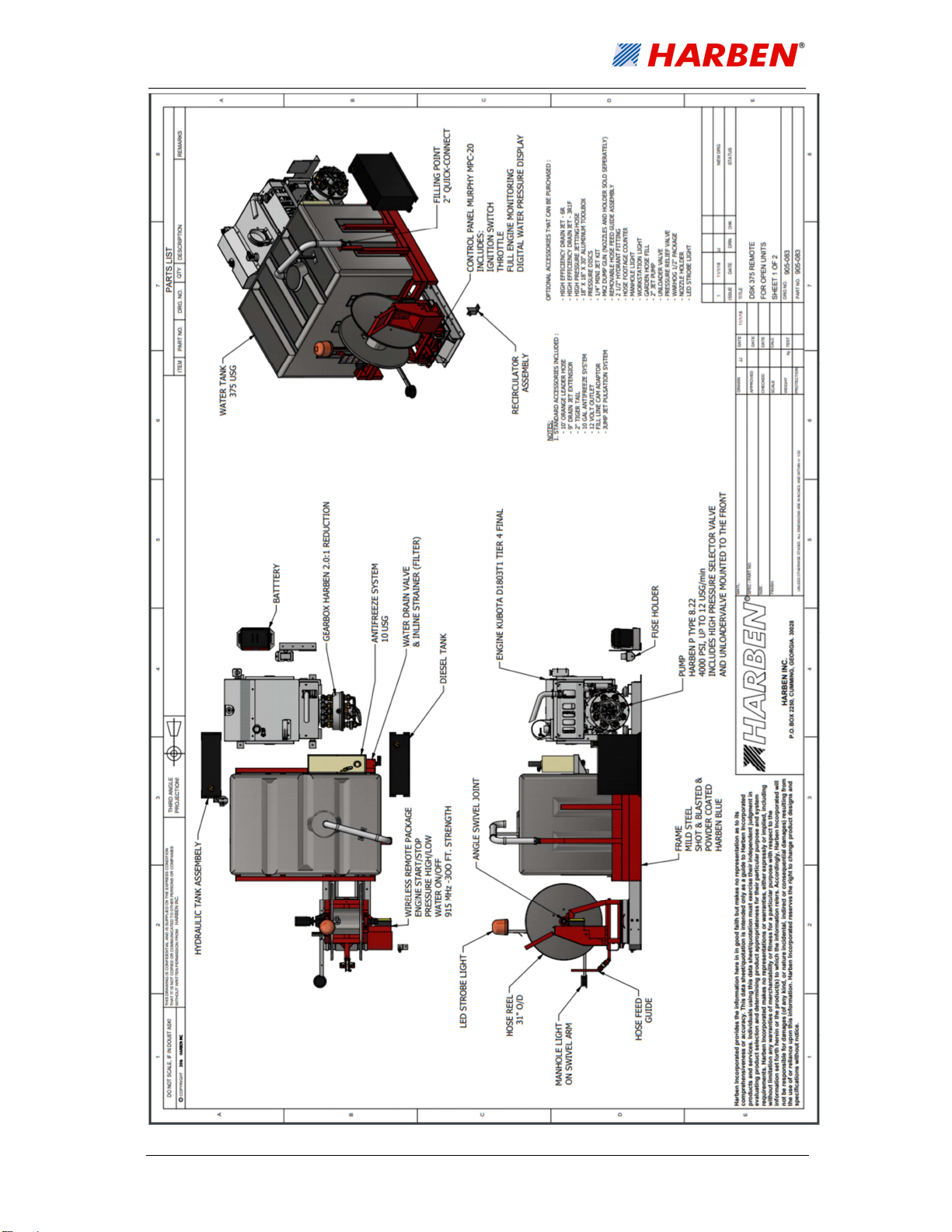
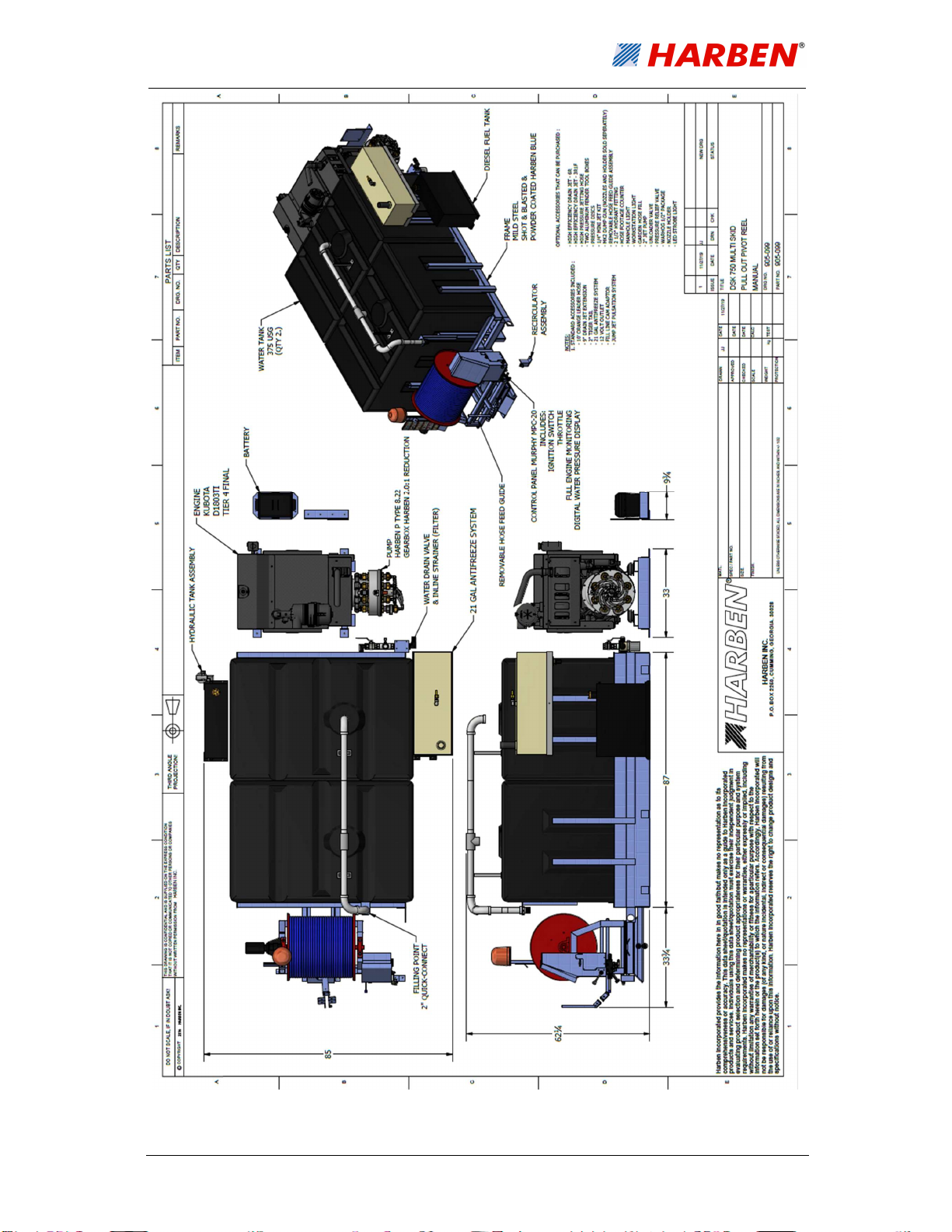
Figures 2.1-2.3 defines the components of the DSK Multi-skid Package assembly as follows:
The pump is driven by an industrial diesel engine.
The engine drives the pump via a 2.21:1 reduction gearbox which reduces the pump rpm
down to the correct shaft speed.
Water is fed from a mains supply into a plastic water storage tank. The tank supplies
the pump with a positive head of pressure via an inline hypro strainer that filters the
water to approximately 80 microns.
The ‘P’ Type 8 22 radial piston high-pressure diaphragm pump is driven by an
industrial diesel engine through a 2.21:1 reduction gearbox.
The water is directed by a divert valve, to a hydraulically driven hose reel with up to 500 feet
of ½” hose, or at low pressure ‘dumped’ back to tank.
The system is protected from over pressurization by a safety relief bursting disc.
The engine and system pressure can be monitored at the control panel situated at
the rear of the skid package.
2.3. Detailed Drawings
Detailed drawings and parts lists for the above components are provided as follows:
The pump is detailed in Section 7.
Details of other parts and assemblies are included at Section 10.

8
Fig. 2.1
–
DSK 4018 375 Manual
Primary Components
9
Fig. 2.2 – DSK 4018 375 Remote Primary Components
10
Fig. 2.3
–
DSK 4018 750 Manual Primary Components

11
Technical Data
3.1. Technical Data
3.1.1. Pump Data
Pump Type Harben ‘P’ Type 8 22 (See Section 8)
Pump diameter 16” approx.
Pump length 15” approx.
Inlet 1 ¼” dia.
Outlet G1/2” (1/2” BSP)
Shaft dia 30 mm
Shaft length 65 mm
Cylinder options 8
Power rating (nominal) 45 hp
Plunger diameter 22 mm
Shaft speed 1250 rpm
Maximum pressure Up to 4000 psi (280 bar)
Max flow rate Up to 18 USG/min (70 lpm)
Crankcase lubrication Fully immersed
Oil capacity 1.3 USG
Weight 176 lb
Recommended crankcase oil Shell Morlina 150 or Tellus 150 (see
section 6)
Max inlet temperature 77°F

12
3.1.2. Main Components
Engine ENGINE KUBOTA D1803TI TIER 4 FINAL
Pump 020041AAB Harben P Type 8 22
Gearbox 012242 Harben P Type 2.21:1
_________________________________________________________________________
3.1.3. Ancillaries
Water tank 375 gal capacity each. 750 gal capacity for 2 tank set.
Supply filter 042134 Hypro line strainer / 170 micron mesh
Monitoring & control Standard engine controller and throttle
Pressure control and safety 011046 Pressure disc white 4000 psi
011047 Pressure disc black 5000 psi
________________________________________________________________________
3.1.4. Services Required
Mains water supply Positive head capable of delivering greater than 16
USG/min
Note: Water pH value of 5 to 9 is recommended.

13
3.2. Technical Description
3.2.1. Primary Components
The primary components of the multi-skid package are illustrated in Figures 2.1-2.3 which are
as follows:
A prime mover in the form of an industrial diesel engine which drives a Harben P Type
high-pressure pump.
The pump is capable of producing high-pressure water up to 4000 psi.
Note: See above or section 7 for performance options.
A hydraulic driven hose reel with up to 500 feet of single wire braid high-pressure hose
with either a nozzle or gun attachment to deliver the high-pressure water to the work
application.
Plastic water tank, acting as a reservoir, also ensuring the water is settled and non-
turbulent, discharging a smooth uninterrupted supply, with a positive head of pressure
to the inlet, maximising the full potential of the pump.
The pressure valve directs high-pressure water to the main jetting hose or diverts it
back to the tank.
The control panel which includes the engine controller, pressure gauge, throttle, high-
pressure selector, jump jet valve & hydraulic hose reel controls.
A Hypro 80 micron mesh inline strainer is fitted to the suction line between the tanks
and the pump inlet.
3.2.2. Engine Monitoring
Engine oil pressure and hours run are monitored on the engine control panel.
NOTICE: This is a critical component which ensures that no contaminants are drawn into the
pump inlet. This filter must be inspected and cleaned daily, if it becomes blocked it will cause
the pump to cavitate.

14
Operation
4.1. Operating Conditions
Operators of water jetting equipment should be fully conversant with the 'Industry Best
Practices for The Use of High-Pressure Water Jetting Equipment’, hereafter referred to as
'The Code of Practice'. A copy of The Code of Practice is available upon request.
Please ensure that you read this Operation & Maintenance Manual in conjunction with the
Health & Safety Manual before operation.
4.2. Daily Checks
Carry out all daily checks. Full maintenance checks are detailed in Section 5 - Routine
Maintenance.
They are:
pump oil level
gearbox oil level
water filter cleanliness
engine oil level
tank water level
4.3. Pre-start Checks & Procedures
1. WARNING! In cold weather check that machine is not frozen before starting (see
Antifreeze section 4.11). Serious injury can occur from ice bullets. (H&S Sections 3
and 7)
2. Only operate the machine in a well-ventilated area. (H&S Sections 3, 8, 9, and 12)
3. Ensure the vehicle is parked on a level surface, and the hand brake is applied. (H&S
Sections 3, 11, and 13)
4. To fill water tank, connect water supply to the hydrant fitting on the street side of the
unit. (NOTICE: To comply with water authority bylaws never fill the tank by putting a
hose directly inside). The water will fill the tank via an appropriate filling point.
5. Feed off the hose reel approximately 10 feet of high-pressure hose. Do not fit the
nozzle or gun at this point! (H&S Section 16)
6. WARNING! Inspect hose before using. Damaged hose can lead to serious injury
if put under pressure. (H&S Section 3, 6, and 16)
15
Speed up
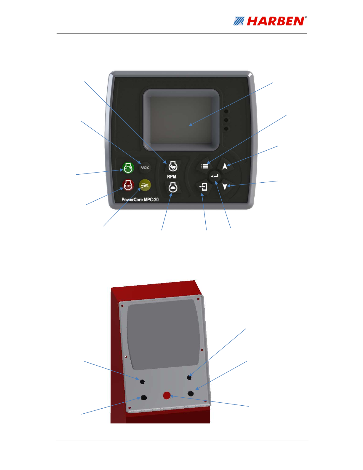
4.4. Control Panel Layout and Function
4.4.1. Control Keys
4.4.2. Toggle Switch Operation
Engine stop
Water on Speed down Menu exit
Menu password
access
Menu down key
Radio on/off
screen
Engine start
Menu up key
Operating screen
Enter button
Light switch
Light fuse
12V charge point
Control panel fuse
Power on switch
16
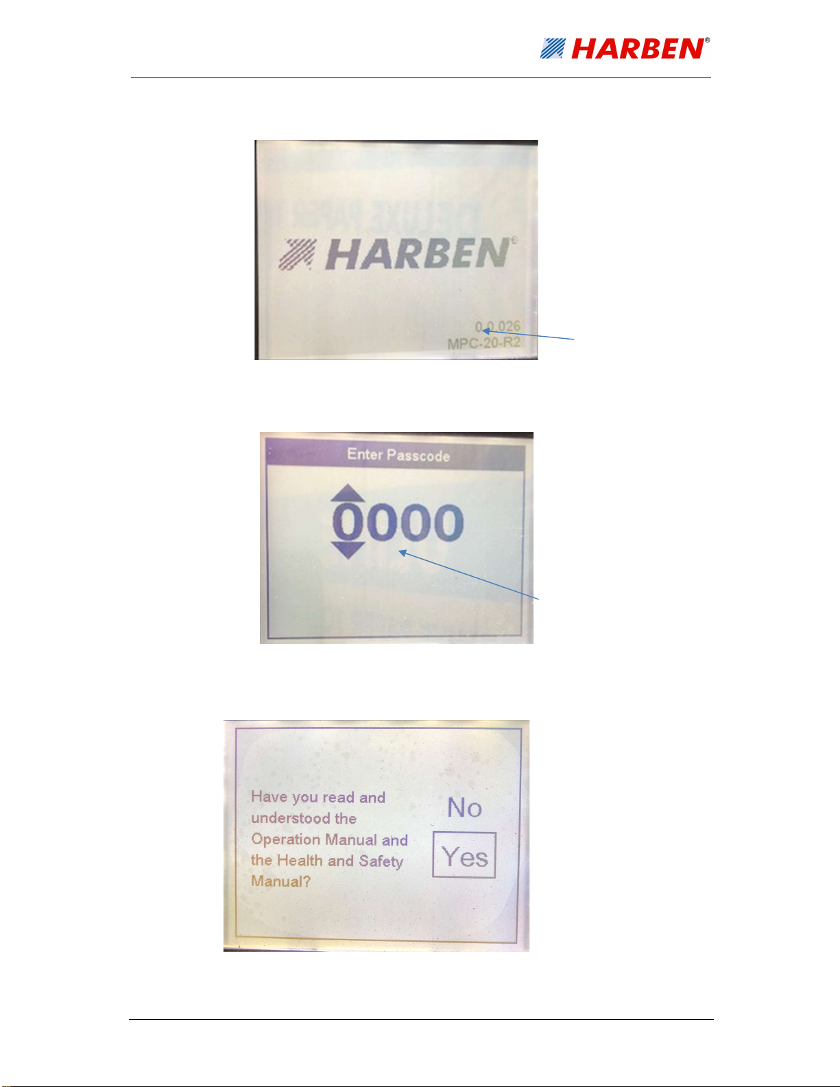
4.4.3. Screen Layouts
Starting splash screen
Password screen
Manual Confirmation Screen
Software version
Password screen – Use
enter, up and down
buttons to enter
password
Run screen entry – 2010
Minor programme
updates - 1111
17
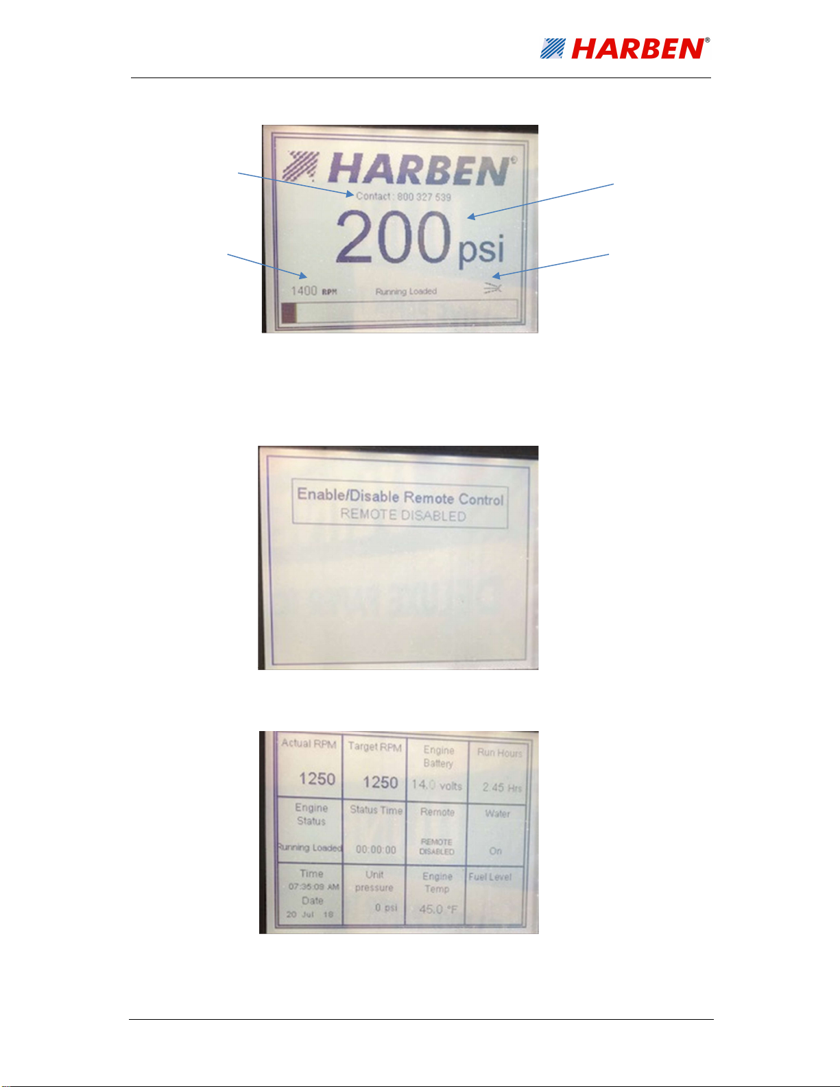
Unit pressure
Engine speed
Harben contact number
Water on
indication
Main run screen (access by pressing menu exit key)
Remote enable/control screen (Enter button will toggle between function)
Run detail screen (access via the up and down keys)

18
Button 6 – menu scroll
Speed/pressure down
c
Engine start/stop
4.4.4. Radio Control layout
4.5. Running the Engine (Manual Mode)
If your machine is fitted with a radio remote control go to section 4.6. (H&S Sections 3, 4, 8,
9, 11, 15, and 16)
Tank water level
Ensure you have an adequate water supply and that the water tank is filled to the ball valve
shut off level.
If your machine is fitted with a radio remote control go to section 4.6.
1. Switch on unit using toggle switch.
2. The control system will now go through a prestart (glow plugs).
3. Enter password ‘2010’ to enter.
4. You will now enter the run screen.
5. Press the engine start button.
6. The engine will now start and run in idle.
7. The user can now increase and decrease the speed of the engine using the engine up
and down speed.
8. Increase the speed of the engine and when it is safe to turn the water on, press the
water on button.
9. The engine speed and pressure can now be increased and decreased using speed up
and speed down button.
10. Radio mode will not operate when manual mode is selected.
Radio control screen
cc
Water on/off
cc
Speed/pressure up
cc
Button 5 – menu scroll
cc
NOTICE: Do NOT allow unfiltered water into the pump.
Table of contents
Other HARBEN Water Pump manuals


Popular Water Pump manuals by other brands


Pentair
Pentair Hypro Series Original instruction manual

Macnaught
Macnaught FTP120-001 instruction manual

BLACKMER
BLACKMER CRL4B Installation, operation and maintenance instructions

Gardner Denver
Gardner Denver GD-2500Q QUINTUPLEX Operating and service manual

Debem
Debem DM10 Instructions for use and maintenance

Walrus
Walrus PW-A Series instruction manual