1
Section 1 – Introduction & Contents
1.1.
Contents
SECTION 1 – INTRODUCTION & CONTENTS ....................................................................1
1.1. C
ONTENTS ....................................................................................................................1
1.2. INTRODUCTION ..............................................................................................................4
1.3. SCOPE OF THIS MANUAL ................................................................................................5
1.4. THE TRAILER JETTER ....................................................................................................5
1.5. COMPOSITION OF THIS MANUAL......................................................................................6
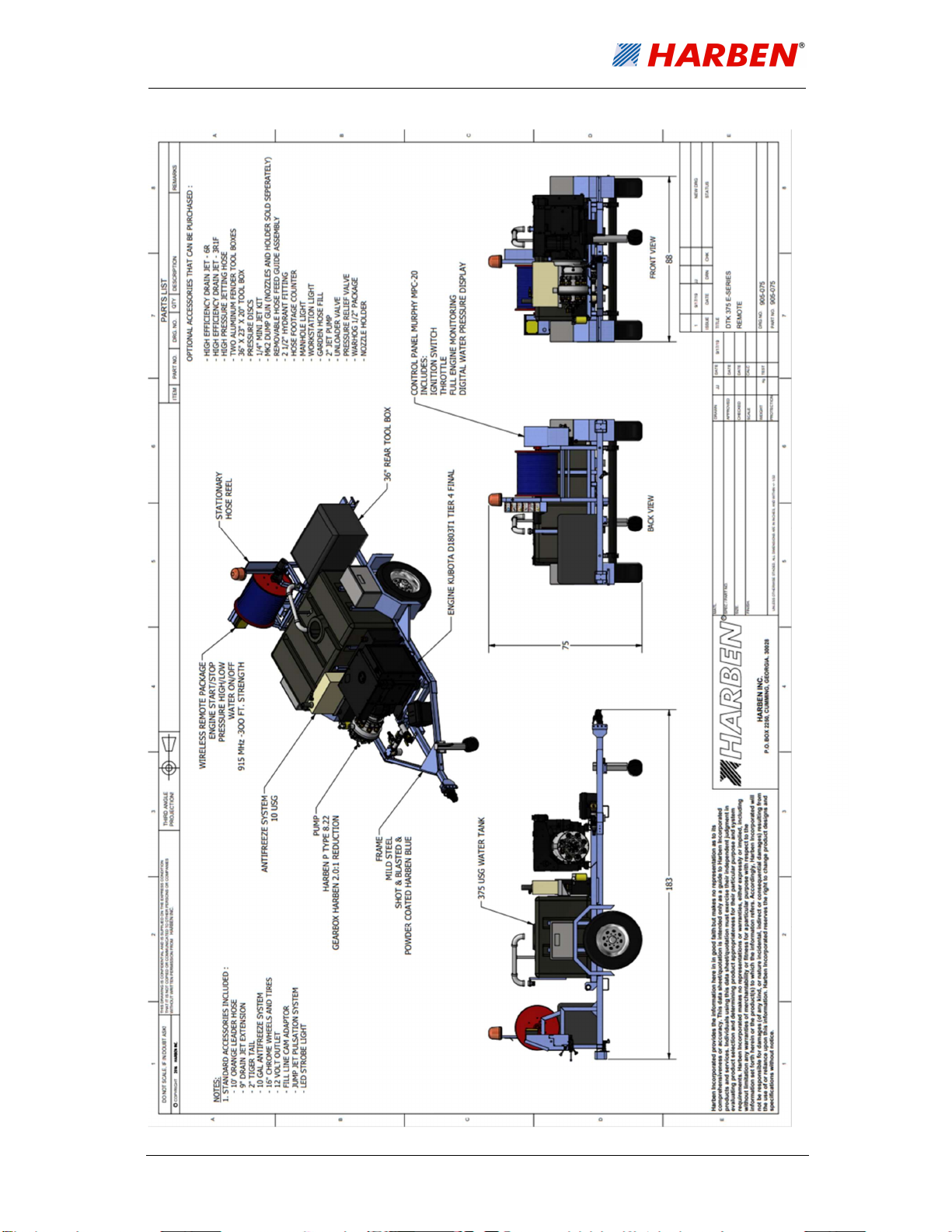
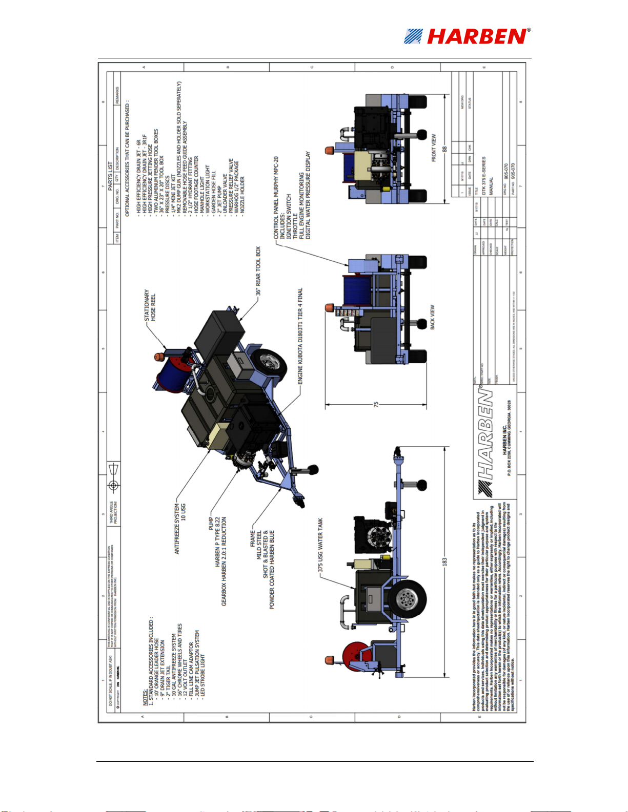
SCOPE OF SUPPLY ......................................................................................................7
2.1. SCOPE OF SUPPLY ........................................................................................................7
2.2. PUMP ASSEMBLY ..........................................................................................................7
2.3. DETAILED DRAWINGS ....................................................................................................7
TECHNICAL DATA ...................................................................................................... 14
3.1. TECHNICAL DATA ........................................................................................................ 14
3.1.1. PUMP DATA .............................................................................................................. 14
3.1.2. MAIN COMPONENTS .................................................................................................. 15
3.1.3. ANCILLARIES ............................................................................................................ 15
3.1.4. SERVICES REQUIRED ................................................................................................ 15
3.2. TECHNICAL DESCRIPTION ............................................................................................ 16
3.2.1. PRIMARY COMPONENTS ............................................................................................ 16
3.2.2. ENGINE MONITORING ................................................................................................ 16
OPERATION ................................................................................................................ 17
4.1. OPERATING CONDITIONS ............................................................................................. 17
4.2. DAILY CHECKS ............................................................................................................ 17
4.3. PRE-START CHECKS & PROCEDURES ........................................................................... 17
4.4. CONTROL PANEL LAYOUT AND FUNCTION ..................................................................... 18
4.4.1. CONTROL KEYS ........................................................................................................ 18
4.4.2. TOGGLE SWITCH OPERATION .................................................................................... 18
4.4.3. SCREEN LAYOUTS .................................................................................................... 19
4.5. RUNNING THE ENGINE (MANUAL MODE)........................................................................ 21
4.6. RUNNING THE ENGINE (RADIO MODE) ........................................................................... 22
4.7. RUNNING THE NOZZLE/JET ........................................................................................... 22
4.8. HARBEN
®
JUMP JET .................................................................................................... 23
4.9. BYPASS VALVE OPERATION ......................................................................................... 24