HARBEN Eliminator VanPack Manual
Harben Inc.
P.O. Box 2250, Cumming, GA 30028
Toll Free: (800)-327-5387 Tel: (770)-889-9535 Fax: (770)-887-9411
email: sale[email protected]m web: www.harben.com
_________________________________________________________________________________________
Operation & Maintenance Manual
Original Instructions
Eliminator Van Pack
903-1315
Section 1 Introduction
Section 2 Scope of Supply
Section 3 Technical Data
Section 4 Operation
Section 5 Routine Maintenance
Section 6 Fault Finding
Section 7 Pump
Section 8 Engine
Section 9 Wiring and Circuit Diagram
Section 10 Parts List / Spares / Auxiliary components
Section 11 Service Documents
Section 12 Warranty & Certification
Section 13 Health & Safety Manual 903-1308
Read the Health and Safety Manual before
operating any equipment. Failure to do so could
cause serious injury or death.
2
Operation & Maintenance Manual for:
UNIT: Eliminator Van Pack R/1 (B11238/A)
ISSUE DATE: 6/20
ISSUE No: 3
AMENDMENTS
Change Changes Date Signature
1 NEW ADDITION 5/20 GT
2 Added Anti-Freeze System Pictures 6/20 GT
3 Updated manual to code 6/20 GT

3
1. Introduction
1.1. Contents
1. INTRODUCTION ........................................................................................................... 3
1.1. CONTENTS ................................................................................................................... 3
1.2. INTRODUCTION ............................................................................................................. 6
1.3. SCOPE OF THIS MANUAL ............................................................................................... 7
1.4. THE ELIMINATOR VANPACK ........................................................................................... 7
1.5. COMPOSITION OF THIS MANUAL..................................................................................... 8
2. SCOPE OF SUPPLY ..................................................................................................... 9
2.1. SCOPE OF SUPPLY ....................................................................................................... 9
2.2. VANPACK ASSEMBLY ................................................................................................... 9
2.3. DETAILED DRAWINGS ..................................................................................................10
3. TECHNICAL DATA ......................................................................................................14
3.1. TECHNICAL DATA ........................................................................................................14
3.1.1. PUMP DATA .............................................................................................................. 14
3.1.2. MAIN COMPONENTS .................................................................................................. 14
3.1.3. ANCILLARIES ............................................................................................................ 14
3.1.4. SERVICES REQUIRED ................................................................................................ 14
3.2. TECHNICAL DESCRIPTION ............................................................................................15
3.2.1. PRIMARY COMPONENTS ............................................................................................ 15
3.2.2. ENGINE MONITORING ................................................................................................ 15
3.2.3. DELIVERY HOSE REEL ............................................................................................... 15
4. OPERATION ................................................................................................................17
4.1. OPERATING CONDITIONS .............................................................................................17
4.2. DAILY CHECKS ............................................................................................................17
4.3. PRE-START CHECKS & BLEED PROCEDURE ..................................................................18
4.4. STARTING THE ENGINE & SETTING THE OPERATING PRESSURE .....................................19
4.5. PRE-START CHECKS & PROCEDURES ...........................................................................20
4.5.1. STARTING THE ENGINE .............................................................................................. 20
4.5.2. CHECKING THE OPERATING PRESSURE WITH A NOZZLE FITTED ................................... 21
4.5.3. CHECKING THE OPERATING PRESSURE WITH A GUN FITTED ........................................ 22
4.6. REMOTE OPERATION STARTING PROCEDURE ................................................................23
4.6.1. STARTING THE ENGINE .............................................................................................. 23
4.7. RAPID SHUTDOWN .......................................................................................................25
4.8. AUTOMATIC SHUTDOWN ..............................................................................................25

4
4.9. HOSE REEL WINDING AND UNWINDING .........................................................................25
4.10. FROST PRECAUTIONS ................................................................................................26
5. ROUTINE MAINTENANCE ...........................................................................................28
5.1. MAINTENANCE PROCEDURES .......................................................................................28
5.2. GEARBOX LUBRICATING CHART – SPECK NP25 ...........................................................29
5.3. GENERAL TORQUE SETTINGS .......................................................................................30
5.4. DAILY MAINTENANCE ...................................................................................................31
6. FAULT FINDING ..........................................................................................................33
6.1. EQUIPMENT FAULT FINDING .........................................................................................35
6.2. SELECTOR FAULT FINDING ...........................................................................................35
7. PUMP ...........................................................................................................................36
8. ENGINE ........................................................................................................................37
9. CIRCUIT AND WIRING DIAGRAMS ............................................................................38
10. PARTS LISTS / SPARES .............................................................................................42
10.1. INTRODUCTION ..........................................................................................................42
10.2. ORDERING SPARE PARTS ..........................................................................................42
10.3. ACCESSORIES & CONSUMABLES ................................................................................43
10.3.1. ROUTINE MAINTENANCE ............................................................................................ 43
10.3.2. CONSUMABLES ......................................................................................................... 43
10.3.3. ACCESSORIES .......................................................................................................... 43
10.4. PARTS LIST ...............................................................................................................45
10.5. HYDRAULIC DIVERTOR VALVE ASSEMBLY ...................................................................51
10.5.1. RECOMMENDED TOOLS ............................................................................................. 51
10.5.2. SERVICE KITS ........................................................................................................... 51
10.6. TO DISMANTLE ..........................................................................................................52
10.7. TO ASSEMBLE ...........................................................................................................52
11. SERVICE DOCUMENTS ..............................................................................................57
11.1. SERVICE CHECKLIST ..................................................................................................57
11.2. SERVICE LOGBOOK ...................................................................................................58
12. WARRANTY .................................................................................................................59
12.1. WARRANTY OF NEW PRODUCTS: ................................................................................59
12.2. WARRANTY OF SPARE PARTS: ...................................................................................59
12.3. LIMITATIONS OF WARRANTY:......................................................................................61

5

6
1.2. Introduction
Please ensure that you read this Operation & Maintenance Manual in conjunction with the
Health & Safety Manual before operation.
Within this manual, the health and safety risks are highlighted with specific symbols. These
will be referenced to sections within the Health and Safety Manual which you are required to
read. The sections to refer to in the manual will be labelled at the end of the highlighted
statement (Ex. H&S Section 2). There are three symbols that will be used to differentiate the
levels of severity. They are as follows:
o : This is the symbol for . This means that if an accident were to happen,
it would cause minor to moderate injury.
o : This is the symbol for . This means that if an accident were to happen,
it could result in a serious injury or possible death.
o : This is the symbol for . This means that if an accident were to happen,
it will result in death or serious injury. This will only be shown for the most extreme
cases.
It is imperative that these symbols are paid attention to as to avoid any sort of injury.
Notices
Carefully read the notices of this manual because they give important information concerning
safe installation, use and maintenance; familiarise yourself with the workings of the machine
to rapidly switch it off and eliminate pressure.
This manual is an integral and essential part of the product; it must be consigned to the user
to ensure the training/information for personnel.
The manufacturer does not assume responsibility for damage caused to persons, property or
to the machine, in the case of improper use. Carefully preserve this manual for any further
consultation.
Identify the model of your machine by reading the details on the identification plate. Upon
delivery, inspect the machine / accessories for any damage, which may occur during transport.
Always follow the recommended operating procedures. Do not misuse the
equipment as this could result in injury or mechanical breakdown!

7
1.3. Scope of this Manual
This manual provides operation and maintenance instructions for the unit. Where the unit has
been fitted with proprietary components, details of these are also included in this manual.
This manual is compiled to match the Scope of Supply detailed in Section 2. All specifications,
descriptions and parts lists refer only to the components in the version of the unit detailed in
this scope of supply.
Maintenance instructions included in this manual include:
Routine maintenance to be carried out at specific times.
Maintenance of the high-pressure pump.
Repairs to the pump crankcase are not considered maintenance operations as these should
be undertaken only by Harben, their approved agents, or at least competent automotive
engineers.
1.4. The Eliminator Vanpack
Harben® drain vanpacks have been designed to the highest standards so that they will work
safely and reliably for many years. It is important that you take time to read the information
provided in this operation and maintenance manual so that you understand how to make the
most of the vanpack in accordance with the instructions. Harben® vanpacks are powerful
pieces of industrial equipment and should only be operated by competent users who
understand that serious injury or death can occur through misuse.
The Eliminator Vanpack is a highly versatile mobile high-pressure water jetting unit, which
offers the benefits of proven power pack and pump performance with a comprehensive range
of accessories.
Developed for a wide range of water jetting applications, the Unit has been meticulously
designed for safe and efficient use.
Additional accessories can be purchased from Harben®, such as: floor cleaners, jetting guns
and jet pumps which extend the range of work that can be carried out with the jetter. Safety
information relating to individual accessories is provided later in this section.

8
1.5. Composition of this Manual
This manual comprises the following further sections:
Section 2 Scope of Supply
This section defines the scope of supply of the equipment in compliance with the sales order.
Section 3 Technical Data
This section contains technical information about the unit.
Section 4 Operation
This section describes the recommended operating procedures for the unit.
Section 5 Routine Maintenance
This section details recommended routine maintenance requirements for the pump and unit.
Section 6 Fault Finding
Fault diagnosis tables for the pump, engine, and ancillaries.
Section 7 Pump
This section provides details of the pump and gearbox assembly.
Section 8 Engine
This section provides details about the engine.
Section 9 Circuit and Wiring Diagrams
This section includes the Hydraulic, Water and Electrical circuits including engine controller &
wiring loom.
Section 10 Parts List / Spares
How to identify and order spares
Section 11 Service Documents
Service logbook and checklist.
Section 12 Warranty & Certification
Section 13 Health & Safety Manual 903-1308
This manual details health and safety considerations in general and specific to water jetting
equipment.

9
2. Scope of Supply
2.1. Scope of Supply
Unit: ELIMINATOR VANPACK
2.2. Vanpack Assembly
The General Arrangement drawing: 003-295, defines the components of the Eliminator
Vanpack mounted Pump Assembly as follows:
Water is fed from a “mains” supply through a manual low-pressure inlet hose reel into a plastic
water storage tank. The tank supplies the pump with a positive head of pressure via an inline
Hypro strainer that filters the water to approximately 177 microns, (Pump is specified at
200microns)
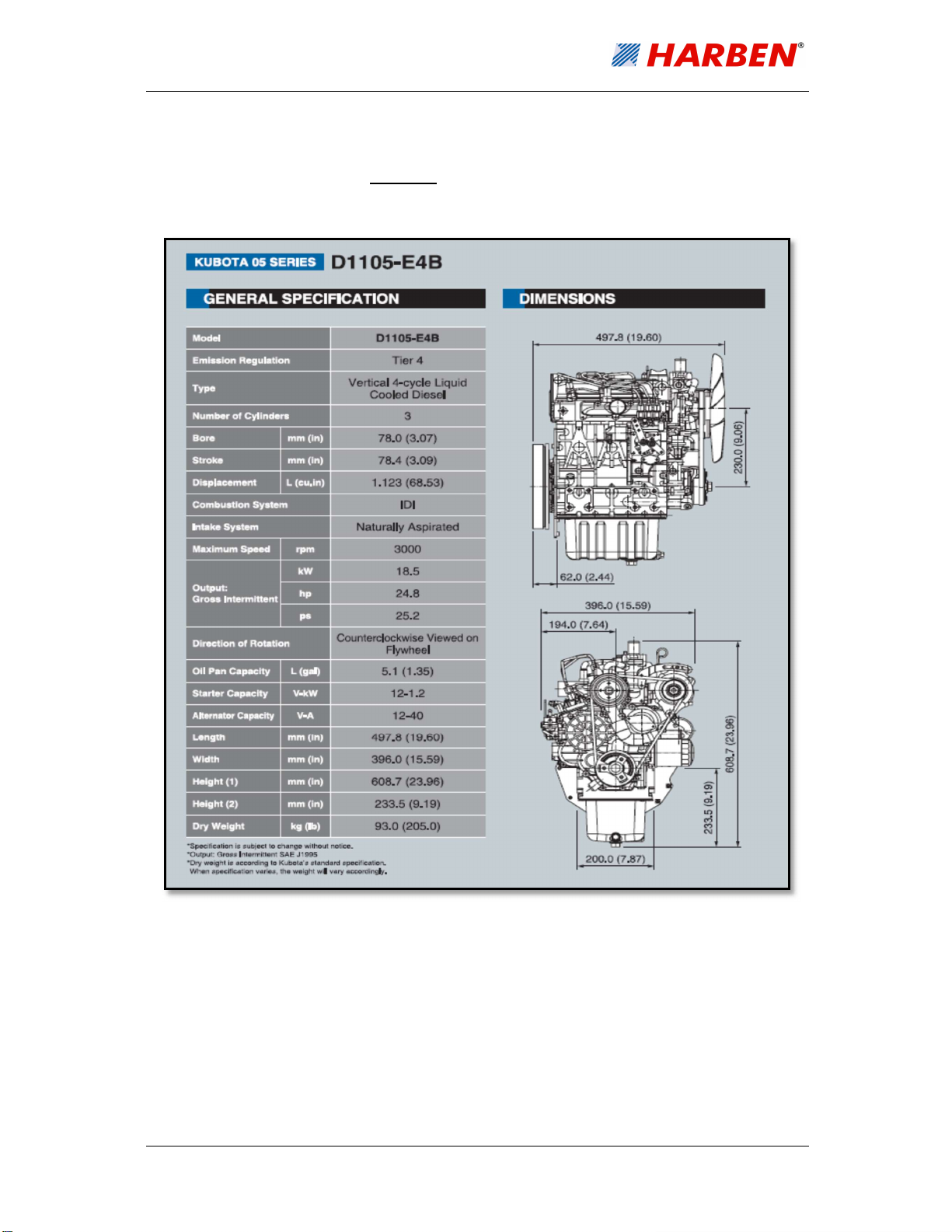
The Speck high-pressure plunger pump is driven by a Kubota D1105-E4B-EU-X1 18.5kW
Stage 5 C-TXT industrial diesel engine through a Speck NP25 gearbox.
The water is directed by an electrically controlled Hydraulic diverter valve, to a hydraulically
driven hose reel c/w 300’ of ½” hose, or at low pressure ‘dumped’ back to tank.
The system is protected from over pressurisation by means of a Hawk safety relief Valve.
The system pressure can be adjusted by means of a Speck UL221 Unloader Valve.
The engine and system pressure can be monitored at the control panel situated at the rear of
the van.
10
2.3. Detailed Drawings
Detailed drawings and parts lists for the above components are provided as follows:
The Speck Pump is detailed in Section 7.
11
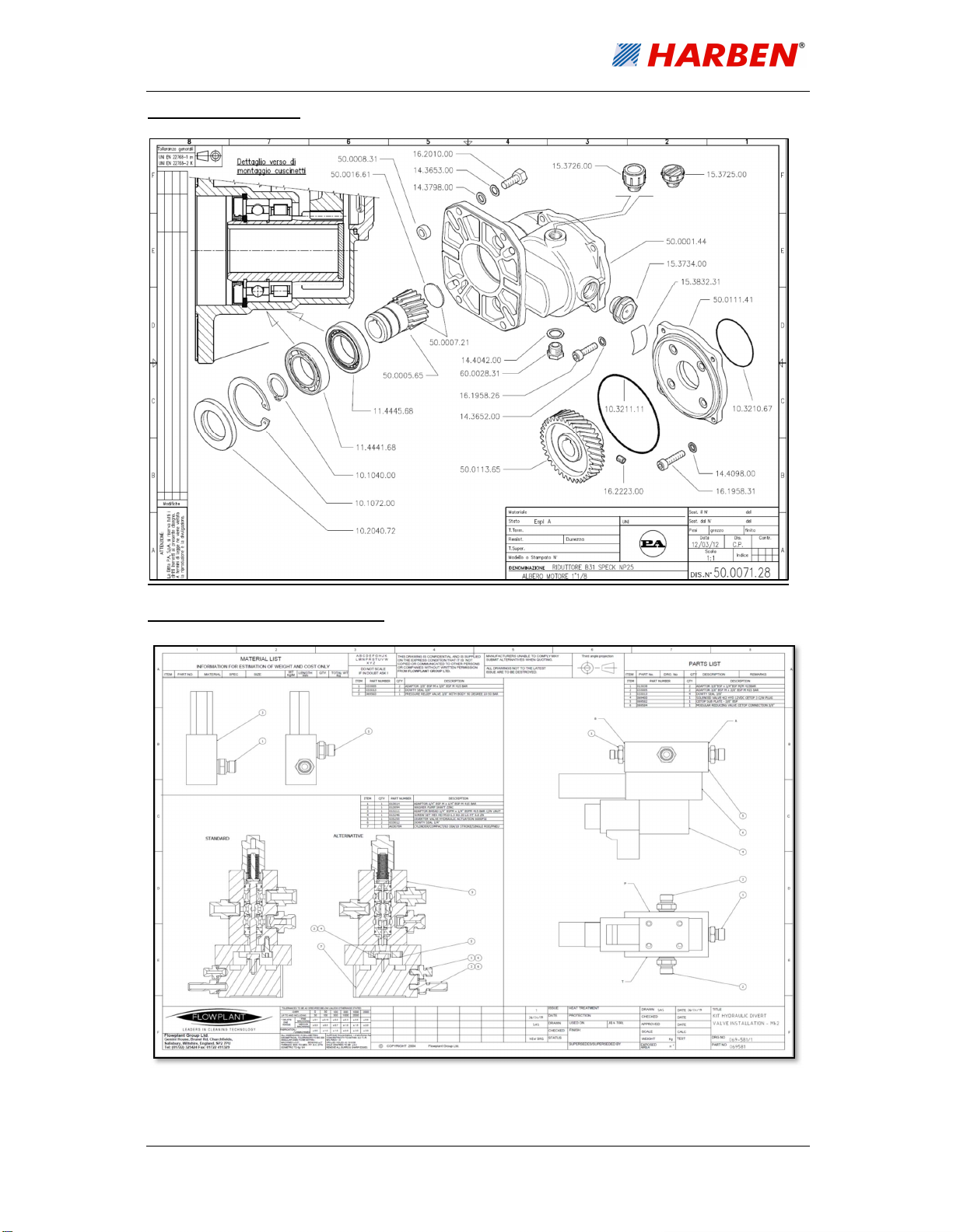
NP25 Gearbox Detail
Hydraulic Diverter Valve 069-581

12
Hawk Safety Relief Valve 035-401

13
Speck Unloader Valve UL221 035-185

14
3. Technical Data
3.1. Technical Data
3.1.1. Pump Data
PUMP TYPE Speck NP25/54-200 [positive displacement]
Number of cylinders 3
Power rating (nominal) 22.5 hp
Plunger diameter 25mm
Crankshaft speed 1450rpm
Maximum pressure 200
Normal operating pressure 200 bar [2900psi]
Flow rate Up to 54 L/min
Crankcase lubrication Splash / Gravity
Crankcase oil capacity 0.24 USG
Recommended crankcase oil ISO VG 220 or SAE 90 Gear oil.
Valves Identical suction & discharge.
NPSH Input 10 bar max. Suction head -0.3 bar.
3.1.2. Main Components
Prime Mover Kubota D1105-E4B-EU-X1 18.5kW Stage 5 C-TXT
Drive Gearbox Speck NP25 Reduction box (2.176:1)
3.1.3. Ancillaries
Water Tank Capacity 88 gals. (400 litres)
Supply Water Filter N05105 Hypro line strainer / 177 micro mesh
Pressure Gauge Digitally Displayed
Safety Relief Hawk (Automatic SRV)
3.1.4. Services Required
Mains Water Supply Positive head.
Note: Water pH value of 5 to 9 is recommended.

15
3.2. Technical Description
3.2.1. Primary Components
The primary components of the Eliminator Vanpack are as follows:
A prime mover in the form of a Kubota 3-cylinder water-cooled diesel engine which
drives a Speck NP25 type high-pressure pump.
The pump can raise the water pressure up to 2900psi (200 bar).
A hydraulically driven hose reel 300 ft of 2 wire braid high-pressure hose with either a
nozzle or gun attachment to deliver the high-pressure water to the selected working
site.
A plastic water tank, acting as a reservoir, ensures the water is settled and non-
turbulent, discharging a smooth lamina flow of uninterrupted air free supply, a positive
head of pressure to the pump inlet and maximising the pumps full potential. The tank
can be filled via the inlet reel by connecting to a mains inlet water supply
o NOTICE: Turbulent water will cause the pump to run unevenly and cause
excessive wear due to cavitation.
Water is diverted to the hose reel either using a 12VDC hydraulic diverter.
A Hypro 177Micron mesh inline strainer is fitted to the suction line between the tank
and the pump inlet.
Note: This is a critical component which ensures that no contaminants are drawn into the
pump inlet. This filter must be inspected and cleaned daily, if it becomes blocked it will cause
the pump to cavitate.
3.2.2. Engine Monitoring
Engine oil pressure and engine coolant temperature, together with alternator charge rate are
continuously monitored. Activation of the engine pressure or temperature switches will cause
an engine shutdown and the respective ‘FAULT’ to be displayed on the control unit.
Alternator failure will be displayed on the control unit.
3.2.3. Delivery Hose Reel
The hose reel drum on which the delivery hose is wound is driven by a powerful OMR315
hydraulic motor directly coupled to the hose reel hub. Hydraulic power is obtained from a
hydraulic gear pump driven from the engine P.T.O. (See below)

16
Note: 050-324 Hydraulic gear pump detail: -
(Ratio 0.844/1.00, Output 4.35 cc/rev, direct mounting, theoretical discharge volume @
3000rpm = 3 gpm, max speed 3200rpm, max pressure 1707psi)
The speed and direction of the reel is controlled by a manual lever-controlled spool valve c/w
safety relief and flow control, this is situated just below and right of the high-pressure hose
reel.

17
4. Operation
4.1. Operating Conditions
Operators of water jetting equipment should be fully conversant with the Water Jetting
Association ‘Code of Practice for the Use of High-Pressure Water Jetting Equipment’,
hereafter referred to as 'The Code of Practice'. A copy of The Code of Practice is available
upon request.
Please ensure that you read this Operation & Maintenance Manual in conjunction with the
Health & Safety Manual before operation.
4.2. Daily Checks
Carry out all daily checks. Full maintenance checks are detailed in Section 5 - Routine
Maintenance.
They are:
Pump oil level
Gearbox oil level
Water filter cleanliness
Engine oil level
Engine coolant level
Tank water level & Cleanliness
Diesel level
Anti-freeze level
Radio Remote fully charged

18
4.3. Pre-start Checks & Bleed Procedure
1. WARNING! In cold weather check that machine is not frozen before starting (see
Antifreeze section 4.11). Serious injury can occur from ice bullets. (H&S Sections 3
and 7)
2. Only operate the machine in a well-ventilated area. (H&S Sections 3, 8, 9, and 12)
3. Park next to suitable clean water supply on a level ground.
4. Ensure vehicle handbrake is applied. (H&S Sections 3, 11, and 13)
5. To fill water tank, connect to water supply. The water will fill the tank via the inlet hose
reel when the tank is full it will flow out the overflow. (NOTICE: To comply with water
authority bylaws never fill the tank by putting a hose directly inside)
6. Feed the end of the high-pressure hose through the hose trace on the swinging arm
in front of the hose reel. Do not fit the nozzle or gun at this point! (H&S Section 3, 6,
and 16)
7. In order to avoid an interruption to the jetting operation please ensure that the hand
held ‘radio control unit’ is fully charged, this is to ensure the radio signal is at full
strength and not compromised while the unit is being operated in ‘remote’ mode.
NOTICE: Do not drop the handheld “radio control unit” (RCU) down a manhole
as this could cause it permanent damage. Please use the lanyard provided.

19
4.4. Starting the Engine & Setting the Operating Pressure
The Vanpack is supplied with a Radio Control System allowing One-man operation ‘OMO’ in
accordance with the 'Single Person Operation’ as detailed in The Code of Practice.
Starting procedures are provided for 'Local' operation where water to the high-pressure hose
is controlled by the operator using the Control unit at the machine, and for 'remote' operation
where water to the high-pressure hose is controlled by the hand-held radio control unit ‘RCU’.
While the remote-control facility is provided for single person jetting operation, it should be
noted that initial pressure check must be made at the pump set. Hence, even with the 'remote'
enabled, all initial pressure checks must be made
Either:
With a single operator and ‘radio control unit’ (RCU) adjacent to the pump set and with
the nozzle secure in a drain or pipe or the gun firmly held in the hand.
Or:
With two people, one at the pump set and one in charge of the nozzle or gun.
Once the required operating pressure has been set, remote operation can be safely conducted
by one person using the handheld ‘radio control unit (RCU)
Tank water level
Ensure you have an adequate water supply and that the water tank is at least ½ full. The
machine WILL NOT RUN if the water tank is empty, this will be indicated by an on-screen
warning on the control panel, clearly marked as ‘low water’ as well as an audible warning. It
is preferable to have a full tank of water and provide the pump with a good positive head.
NOTICE: Do Not allow unfiltered water into the pump

20
4.5. Pre-start Checks & Procedures
4.5.1. Starting the Engine
Pre-start Checks
Ensure the open-ended high-pressure hose is in a safe position, preferably within sight of the
operator at the control panel.
Indirect Injection Diesel Engine Key Start Module Operating Procedure
1. Rocker Switch (Bottom Right of Panel) is the Master On/Off (0)
2. In position (1) (On) auxiliary circuits will be energized, screen will be illuminated.
3. Enter the 4-digit PIN using the up and down arrows to select numbers and the enter
button to select
4. Momentarily press the Green button on the Controller, this will automatically run
through pre-heat and prestart When cold. Engine will start automatically and idle at a
pre-determined engine rpm. **Water will now be circulating through the pump and be
diverted back the water tank
This manual suits for next models
1
Table of contents
Other HARBEN Water Pump manuals


Popular Water Pump manuals by other brands


Wilo
Wilo Yonos MAXO Installation and operating instructions

GORMAN-RUPP
GORMAN-RUPP SFDV3A Installation, operation, and maintenance manual with parts list

BGS technic
BGS technic 1609 instruction manual

KSB
KSB Amarex N series Installation and operating manual

SKC
SKC 224-PCXR8M operating instructions

Grundfos
Grundfos HYDRO MPC instructions

Ingersoll-Rand
Ingersoll-Rand NM2304B-X-X Operator's manual

Becker
Becker U 5.200 operating instructions

FLOWTECH
FLOWTECH flowpress WMDA Operation and maintenance manual

Taconova
Taconova TACOFLOW2 PURE 15 Installation and operating instructions

Bestway
Bestway SALUSPA S100105 owner's manual

Trotec
Trotec TGP 1025 ES operating manual