Harbor Point HF-25GW/GX1b Technical Document

WALL SPLIT DUCTLESS
COOLING
ONLY
AND
HEA
T
PUMP SYSTEMS
Cooling Only Models Heat Pump Models:
HF-25GW/GX1b HFR-25GW/GX1b
HF-35GW/GX1b HFR-35GW/GX1b
HF-51GW/GX1a HFR-51GW/GX1a
HF-70GW/GX1a HFR-70GW/GX1a
9,000 Btu / 12,000 Btu
18,000 Btu
24,000 Btu
Harbor Point Air Conditioners
www.harborpointac.com
INST
ALLA
TION,
OPERATION
AND
MAINTEN
ANCE
MANU
AL

HARBOR POINT WALL SPLIT DUCTLESS SYSTEMS
INSTALLATION, OPERATION AND MAINTENANCE MANUAL
This manual is intended as an aid to a qualified service personnel for proper installation,
operation, and maintenance of Harbor Point Air high efficiency R-410A Wall Split
Ductless Systems. Carefully read these instructions before attempting installation or
operation. Failure to follow these instructions may result in improper installation,
operation, or maintenance, possibly resulting in fire, electrical shock, property
damage, personal injury, or death.
Shipping Damage MUST be Reported to the Carrier IMMEDIATELY!!!
Examine the carton for signs of damage if any is evident open packaging and
check the unit for shipping damage.
TO THE INSTALLER
SAFETY INSTRUCTIONS
Read all instructions before using
the Harbor Point high efficiency
system. Install or locate this sys-
tem only in accordance with these
instructions. Use this system only
for its intended use as described in
this manual.
(1)Retainthis manual forfuturereference.
(2)Before leavingthe premises, review this
manual to be sure the unit has been
installed correctly and run the unit for
one complete cycle to make sure it
functions properly.
To obtain technical service or warranty
assistance during or after the installation
of this unit, check our website at www.
harborpointac.comor call your installing
contractor or distributor. Our technical
service department may be contacted at
1-888-908-9888.
When calling for assistance, please have
the following information ready:
Checkratingplateforcorrectsystem
voltage before installing. Installa-
tion and operation of a system with
the incorrect voltage may result in
malfunction or other issues and will
void the warranty.
The Harbor Point system must
be connected only to a properly
grounded electrical supply. Do not
fail to properly ground this unit.
• Indoor Unit
Model Number
Turn off the electrical supply be-
fore servicing the Harbor Point
system.
• Indoor Unit
Serial Number
Do not use the Harbor Point
system if it has damaged wiring, is
not working properly, or has been
damaged or dropped.
• Outdoor Unit
Model Number
• Outdoor Unit
Serial Number
[Save These Instructions]
• Date of installation
This symbol is an indication of
Important Safety Information.
!
!
2

HARBOR POINT WALL SPLIT DUCTLESS SYSTEMS
!
!
DANGER
INSTALLER SUPPLIED ITEMS
Tampering with the Harbor Point
systems is dangerous and may
result in serious injury or death.
Tampering voids allwarranties. Do
not attempt to modify or change
these units in any way.
• Main System Breaker: Sized per unit
requirements, to be mounted adjacent
to outdoor unit.
• Mounting Hardware: Wall anchors,
condenser pad.
• Vacuum Pump
•Gauge Set : R-410specific.
• High Voltage Interconnect Wiring:
14 AWG wiring from outdoor unit to in-
door unit for power and control. *
•Refrigerant : R-410A required for addi-
tional line sets beyond 16 ft.
* Can be purchased through the factory as an
accessory, (part of the Tube Set Kit below)
PRODUCT DESCRIPTION
The Harbor Point system is an efficient
wall split ductless conditioning system
with cooling capacities from 9,000-24,000
Btu and heat pump capacity of 9,000-
24,000 Btu. Designed for quiet operation
and boasting compact dimensions, the
Harbor Point system includes advanced
features like auto-restart, full feature
remote control.
Comprised of three standard components
the indoor evaporator, the outdoor
condensing unit, and an infrared
handheld remote control are engineered
to the highest performance and reliability.
The evaporator is equipped with
permanent washable air filters as well
as motorized air sweep for enhanced air
circulation, and the condensing unit is
equipped as standard with a high
efficiency rotary compressor.
Harbor point recommends the system for
residential and light commercial cooling
and heating applications and will operate
in standard cooling mode down to 60°F
outdoor temperature.
ACCESSORY
Tube-Set Kit consisting of:
• Refrigerant Line Set - 25 feet of
suction and liquid line, both fully in-
sulated, and flare fittings supplied
on both ends.
•Interconnecting High Voltage Wiring
- 25 feet supplied.
•Additional Condensate Tubing - 6 feet
extra supplied.
FACTORY SUPPLIED ITEM
• Matched System Consisting Of:
Evaporator section and condenser sec-
tion with remote control.
ITEMS FOR CONSIDERATION
Application:
Check the application of the unit prior to
installation, certain applications require
additional components or installation pa-
rameters, such as the need for external
condensate pump or if the system will
need to perform low ambient cooling at
outdoor temperatures below 60°F.
3

HARBORPOINT WALL SPLIT DUCTLESS SYSTEMS
C
HO
O
SING UNIT
M
O
DEL
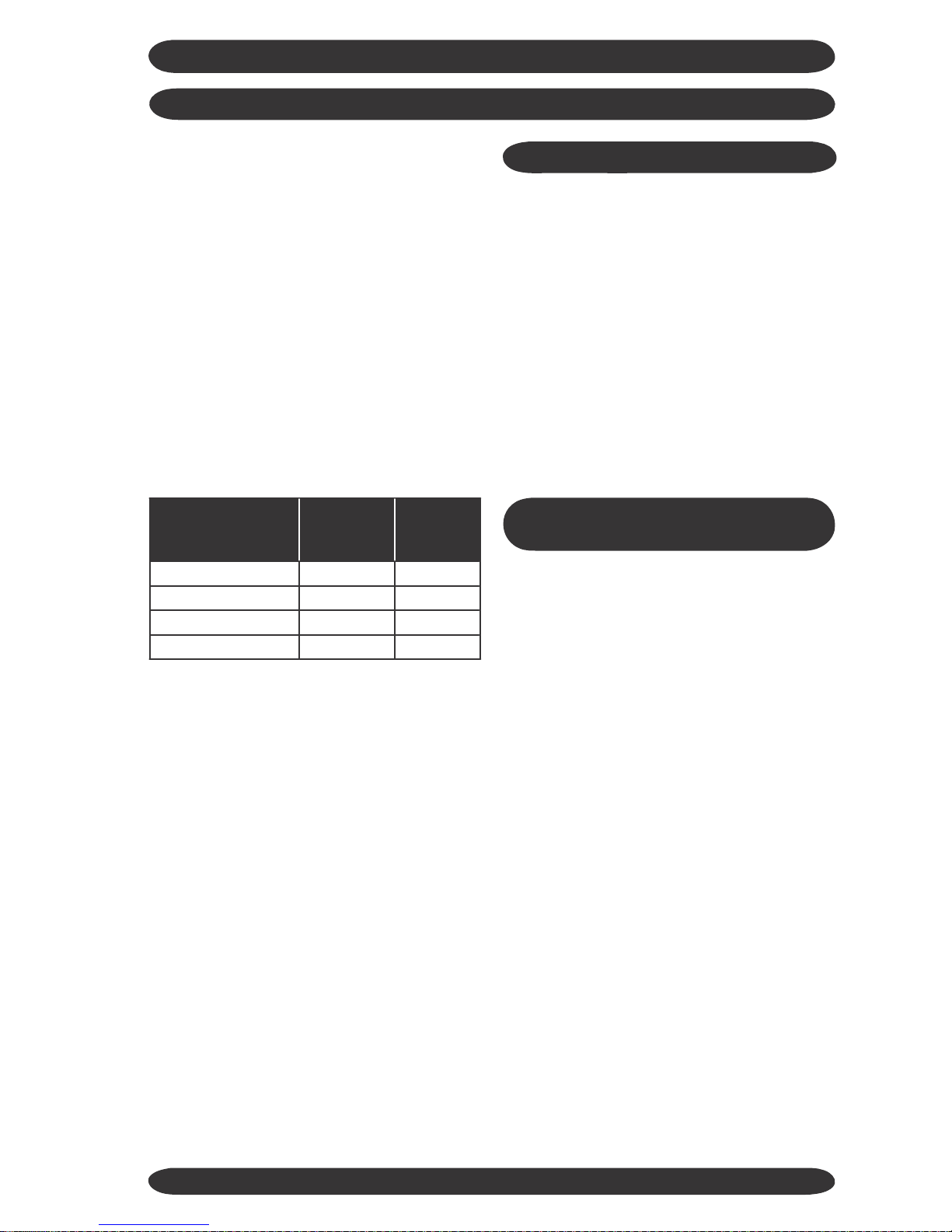
MO
DutyDutyDELS OFFERED
CapacityBtu
ED
CapacityBtuModel#Model#VoltageVoltage
HF‐25G/GX1bCoolingOnly 9,000115‐1‐60
HF‐35G/GX1bCoolingOnly 12,000115‐1‐60
HF‐51G/GX1aCoolingOnly 18,000208/230‐1‐60
HF‐70G/GX1aCoolingOnly 24,000208/230‐1‐60
HFR‐25G/GX1bHeatPump 9,000115‐1‐60
HFR‐35G/GX1bHeatPump 12,000115‐1‐60
HFR‐51G/GX1aHeatPump 18,000208/230‐1‐60
HFR‐70G/GX1aHeatPump 24,000208/230‐1‐60
4
HARBOR POINT WALL SP
LI
TDUCT
LESSSYS
T
E
M
S
PR
E
I
N
S
TALL
A
TI
O
N
Determine the best location for mounting
the indoor unit, it must be located a mini-
mum of 4 ft (6 ft or more recommended)
from the floor and no less than 6” from
the ceiling.
Pay attention to the air circulation in the
room, 9,000 & 12,000 Btu units throw air
15ft, 18,000 & 24,000 Btu units throw air
25ft, ensure no obstacles to airflow exist.
C
O
NT
R
O
L
S
AN
D
C
O
M
P
O
N
E
NT
S
Units are supplied with a wireless remote
control, which communicates with the unit
microprocessor control. The return ai
r
temperature sensor mounted in the in-
door unit provides input to the control fo
r
system operation.
Several modes of operation are available
to the end user depending on the type o
f
comfort required. All unit operating func-
tions are controlled via the remote con-
trol. Refer to “System Operation” section
of this manual.
Locate theindoorandoutdoorunits asclose
together as possible, maximum line set run
and lift MUST NOT BE EXCEEDED. Deter-
mine how the interconnect piping, wiring
and condensate hose are to be run.
Uni
t
Max
Line
Se
t
Run
O
PTI
O
N
AL
C
O
NT
R
O
L
S
AN
D
COMPONENTS
Li
f
t
Max
Ve
r
tical
HF-25
/
H
F
-35
HF-25
/
H
F
-35
50
Fee
t
50
Fee
t
17
Fee
t
17
Fee
t
Low Ambient Control:
Please consult the factory for availability o
f
approved method of low ambient cooling
operation.
HF-51
/
H
F
-70
HF-51
/
H
F
-70
50
Fee
t
50
Fee
t
17
Fee
t
17
Fee
t
HFR-25
/
HFR-35
HFR-25
/
HFR-35
50
Fee
t
50
Fee
t
17
Fee
t
17
Fee
t
HFR-51
/
HFR-70
HFR-51
/
HFR-70
50
Fee
t
50
Fee
t
17
Fee
t
17
Fee
t
C
ondensat
e
Pump:
It is recommended to use the supplied
condensate drain hose in a gravity fed
method whenever possible. If this can
not be done then a field installed pump
that is external to the evaporator would
be required.
Ensure that all panels can be removed for
service as required.
Certi
f
i
cat
i
on:
All Harbor Point Systems are certified by
UL under UL Standard 1995. Per-
formance is varified by CSA under ARI
210/240 test standard.
5

HARBOR POINT WALL SPLIT DUCTLESS SYSTEMS
INDOOR UNIT INSTALLATION
!
!
CAUTION
Follow Instructions, failure to follow
instructions may cause possible mal-
function and void any warranty.
Remove
indoor
and
outdoor
units from
the carton/box. Indoor unit carton con-
tains, remote control and batteries, en-
sure these are kept in a safe place during
installation.
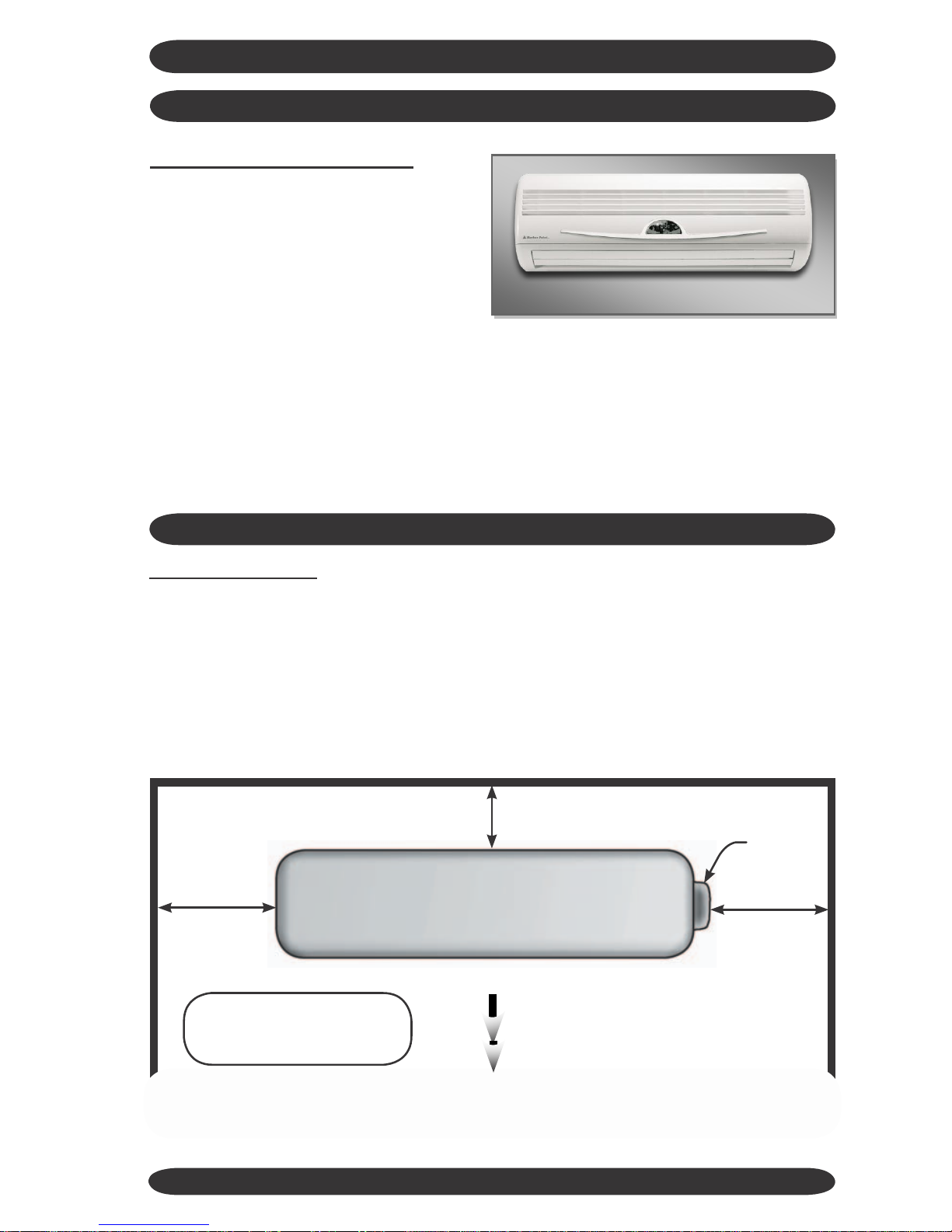
Locate
area
to
install
indoor
unit the
unit should be located a minimum of 6 ft.
from the floor and 6”from the ceiling.
Choose an area where the wall is plumb
and determine how to best to run the unit
interconnects.
CEILING
6” from ceiling minimum
from wall
FLOOR
Ensure no obstacles to airflow are directly
in front of the unit, for a minimum of 12 ft
for 9,000/12,000 Btu units and 16 ft for
18,000/24,000 Btu units.
Do not install the Indoor unit units in areas
exposed to high humidity (Relative Hu-
midity of 80% or more), direct sunlight and
direct heat from stoves or other devices.
6
6” from ceiling m
4ft from floor (minimum)
6ft plus from floor (optimum)
8”
from wall
minimum
8”
minimum
HARBOR POINT WALL SPLIT DUCTLESS SYSTEMS
INDOOR UNIT INSTALLATION
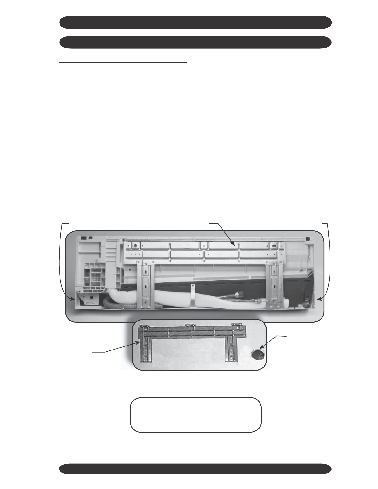
Prepare
the
evaporator
for
mounting
by removing the mounting bracket from
the rear of the indoor unit. Use a Phillips
head screwdriver to remove the unit pipe
strap. If the unit is a heat pump the de-
frost sensor also must be undone from its
retainer.
If mounting the unit on an inside wall, use
the knockouts provided on the left and
right sides of the unit to route the piping
and wiring connections through.
The indoor unit weighs a minimum of
20 Lbs. Use wall anchors to secure the
mounting bracket to a wall stud and en-
sure that the wall is capable of holding the
weight of the unit.
If mounting the unit on an outside wall
measure from the edges of the unit to the
center of the line set 90° bend to locate the
the center of the wall penetration. Drill a
3”ø hole through the wall. Angle the wall
penetration slightly down towards the out-
side to assist in draining the condensate
away from the unit.
Be sure mounting bracket is level, so that
the condensate can drain properly.
knockout
knockout
remove mounting bracket
mounting
bracket
on wall
3”ø hole
Note: Prepare all wiring and piping
connections before hanging the unit
on the mounting bracket.
7

HARBOR POINT WALL SPLIT DUCTLESS SYSTEMS
INDOOR UNIT INSTALLATION
Prepare
unit
line
set
connections
Rotate refrigerant line stubs gently to 90°
(if mounting on an outside wall). For oth-
er line set configurations align the stubs
as required.
Feed the 14 AWG interconnect wiring
between indoor and outdoor through
the unit electrical connection (maxi-
mum number of 6 wires is required) (if
required by local codes an electrical
connector can be attached to the rear
of the unit). Tape the loose wire to the
line set stubs. (See Electrical Wiring In-
stall section.) These two tips save time
and prevent damage to the stubs when
mounting the indoor unit.
Tip: Use Duct tape to tape the Con-
densate hose (make sure it is below
the Line set stubs) and the defrost
sensor (heat pump only). This makes
it easier to guide them through the
hole in the wall.
HEAT PUMP SYSTEMS
Very Important! Make sure the de-
frost sensor wire is run and connected
between the indoor and outdoor units,
or the heat pump system will not oper-
ate in heat mode. Refer to “Heat Pump
Wiring” section of this manual.
duct tape
8
HARBOR POINT WALL SPLIT DUCTLESS SYSTEMS
INDOOR UNIT INSTALLATION
Install
unit
on
mounting
bracket
Feed the line set stubs/condensate hose/
wiring connections through a ø 3” hole in
the wall.
Position the evaporator so that the “key”
slots on the back of the unit slide onto the
tabs on top of the mounting bracket. Then
push the lower portion of the evaporator
against the bracket until it latches into the
mounting bracket.
18,000 Btuh
shown
through the wall penetration, also check
that the wall is plumb. The unit must be
level and plumb for proper condensate
removal.
Indoor unit is now installed, it should be
plumb, level and flush with the wall. In-
sure that the line set stubs are completely
OUTDOOR UNIT INSTALLATION
Locate
Outdoor
unit
Select a location with proper ventilation,
minimizing recirculation possibility. Do not
install the outdoor unit in a location ex-
posed to high winds (field fabricated and
installed wind baffle may be required).
Ensure location does not impede access
around unit and pose a disturbance to
neighboring areas.
Install the outdoor unit on a condenser
service pad. If unit is a heat pump ex-
tend feet to raise 6” to allow for defrost
to drain away.
Clearances for the Outdoor unit:
Front
Condenser Fan
9
12” Minimum Service
Rear Valves
Outdoor Unit
12” Minimum 12” Minimum
Airflow
Note: Consult factory if 48” Minimum
minimum clearances can’t
be maintained.

IR HIGH
WALL
DUCTLESS SPLIT SYSTEMS
OUTDOOR UNIT INSTALLATION
Connect the line set to the stubs. Using
the 2 wrenches, 1 on the male and 1 on
the female tighten the flare nuts. Run the
line set to the outdoor unit, avoid tight
bends and kinking the lines.
If line set length is in excess of that re-
quired, cut line set and re-flare or coil ex-
cess vertically to facilitate oil return to the
compressor.
Install the line set on the
indoor unit stubs.
HARBOR POINT WALL SPLIT DUCTLESS SYSTEMS
Refrigerant Line Set Piping
Interconnecting line set between the
outdoor unit and the indoor unit, must have
both refrigerant lines insulated as the
expansion device is located in the outdoor
unit.
Gently bend the line set stubs from the
in- door unit to the desired location.
Using 2 x 10”/12” Crescent wrenches
remove the flare nuts from the indoor
unit line stubs.
The indoor unit is filled with a dry
gas, check for release of this to ensure
that no leaks are present. Use a small
amount of vacuum pump oil on the male
flare threads to ease installation.
Service port
Gas line service valve
Line set connections
under the GRAY
caps.
Outdoor
Unit
Liquid line service valve
9,000/12,000 Btu model shown.
(18,000/24,000 Btu models have
an additional liquid line port.)
remove line
set cover
Indoor Unit
10

HARBOR POINT WALL SPLIT DUCTLESS SYSTEMS
OUTDOOR UNIT INSTALLATION
Evacuation
Gauges can now be attached to the service
ports - SERVICE PORTS HAVE A 1/2”
CONNECTION TO GAUGES, which is dif-
ferent from the norm for R-22. You will need
specific hoses or an adaptor for the 1/2”
connection.
Once the gauges are attached the line
set can be leak checked using Nitrogen
at 300 psig. Evacuate the unit and inter-
connect down to a minimum of 400-500
Microns, break vacuum with Nitrogen to
further leak check.
Re-evacuate the system down to 300-400
Microns or lower for a period of one hour.
This is an R-410A System it is essential
that a deep vacuum be pulled on the sys-
tem to remove all traces of moisture. See
“System Start-Up”section to fine-tune the
refrigerant charge.
Main
Power
Wiring
Electrical wiring should be done in ac-
cordance with all National Electrical Code
(NEC) and local state/city building codes.
Note: A small screwdriver is required
for unit terminals.
Breaker size and wiring must be sized
for the rating plate amperage, MCA and
HACR. Use only HACR type breakers,
each system installed must have a sep-
arate branch
breaker/fuse.
circuit with an individual
Max
tion. Ground connection must be made to
the terminal plate.
Heat Pump (208/230 V) unit terminals:
L1 - L2 : Power from breaker + G
L3 - L4 : Power to indoor unit + G
1 - 2 - 3 : Control signals
These are just examples of typical wiring
connections.AlwaysrefertoWireDiagram
on unit for actual wiring connections.
A local disconnect should be installed ad-
jacent to the outdoor unit in accordance
with National and Local Codes. The out-
door unit provides power for the indoor
unit, no disconnect is required between
the outdoor and indoor units.
Line voltage from the disconnect should
be wired to:
N - L (115V Unit), + G
L1 - L2 (208/230V Unit), + G
Remove right side knockout on the termi-
nal access panel for whip/wiring connec-
Tip: For easier access to the terminals in the
outdoor unit remove the lower access panel to
installwhipand sealtiteconnectors forconduit.
11
Electrical Specifications
Nominal
Capacity
Btuh
Volts/Hz/Ph
Compressor
Cond Fan
Indoor Fan
Total
FLA
MCA
HACR
Fuse
RLA
LRA
Watts
RLA
Watts
RLA
HF-25, HF-35, HF-51 & HF-70 Cooling Only
9,000
115/60/1
7.5
47
35
0.81
16
0.35
7.2
10.6
15.0
12,000
115/60/1
9.9
53
45
0.80
16
0.35
9.6
14.0
20.0
18,000
208/230/60/1
6.6
42
60
0.85
40
0.40
6.4
9.5
15.0
24,000
208/230/60/1
10.0
46
60
0.90
40
0.40
8.1
13.8
23.8
HFR-25, HFR-35, HFR-51 & HFR-70 Heat Pump
9,000
115/60/1
7.5
47
35
0.81
16
0.35
7.2
10.6
15.0
12,000
115/60/1
9.9
53
45
0.80
16
0.35
9.6
14.0
20.0
18,000
220/60/1
6.6
42
60
0.85
40
0.40
6.4
9.5
15.0
24,000
208/230/60/1
10.0
46
60
0.90
40
0.40
8.1
13.8
23.8

HARBOR POINT WALL SPLIT DUCTLESS SYSTEMS
OUTDOOR UNIT INSTALLATION
Electrical
Wiring
Installation
outdoor unit must be a point to point i.e.
the terminal that the wire is attached to on
the outdoor unit must be the same termi-
nal it is wired to in on the indoor unit.
!
!
CAUTION
Electrical Wiring should be done by a
certified electrician in accordance with
all National ElectricalCode (NEC) and
local state/city building codes.
THIS IS EXTREMELY IMPORTANT:
Switching the L3 - L4 or N1 - L1 wires
will allow the indoor unit to operate
but it will not provide controls signals
for the outdoor unit so that the com-
pressor will not operate. Ground con-
nection should be made to ground
screw marked in indoor unit.
ALL
CONTROLS
WIRING
BETWEEN
IN-
DOOR
AND
OUTDOOR
UNIT
IS
HIGH
VOLTAGE
MINIMUM
14
AWG
WIRE
MUST
BE
USED.
Remove terminal covers from indoor unit
and wire to the terminals, (small screw-
driver required). Control wiring from the
COOLING ONLY WIRING
Control wiring at outdoor unit (cooling only).
Ground wires connected to the terminal
plate indoor and outdoor units must be
grounded.
Connection
of
wires
for
outdoor
unit
and
indoor
unit
(115V Models)
Outdoor
unit
Indoor
unit
(cooling
only
model)
source
(208/230V Models)
Outdoor
unit
�
To
power
source
Indoor
unit
(cooling only model)
12
1
L3
L4
L1
L2
L3
L4
1
T
o power
1
L1
N1
L
N
L1
N1
1
HARBOR POINT WALL SPLIT DUCTLESS SYSTEMS
OUTDOOR UNIT INSTALLATION
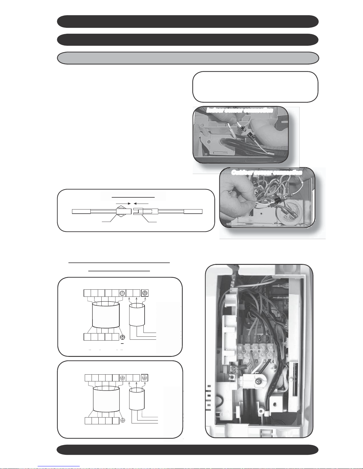
HEAT PUMP WIRING
If the system is a heat pump the defrost
sensor must be connected from the in-
door unit to the defrost sensor in the out-
door unit. Standard lead length is 25 ft,
if a longer length is required then cut the
lead and extend using thermostat wire.
The heat pump defrost sensor intercon-
nect wire comes bundled up with the indoor
units. It then should be “un-bundled” and
connected to the molex connection at the
indoor unit and run to the outdoor unit molex
connection, typically with the interconnect-
ing wiring and/or interconnecting tubing.
Note: use ofcolored wire (supplied with
line set) and defrost sensor connected
(heat pump only).
Indoor sensor connection
Outdoor sensor connection
Indoor
wire
connector
outdoor probe wire connector
for defrosting
Ground wires connected to the terminal plate on indoor and
outdoor units must be grounded.
Connection
of
wires
for
outdoor
unit
and
indoor
unit
(115V Models)
Outdoor
unit
�
Indoor
unit
To power
source
(heating model)
(208/230V Models)
Outdoor
unit
�
�
To
power
source
Indoor
unit
(heating model)
13
1
2
3
L3
L4
L1
L2
1
2
3
L3
L4
1
2
3
L1
N1
L
N
1
2
3
L1
N1
Defrost
Sensor
HARBOR POINT WALL SPLIT DUCTLESS SYSTEMS
OUTDOOR UNIT INSTALLATION
12) Condensate Hose:
The unit is provided with approximately
18” of condensate hose connected. Hose
connection is sized to accept a 3/4” OD or
5/8” ID clear plastic hose to then extend to
building drain.
All condensate hose extensions should be
in accordance with local building codes.
Remember water only flows downhill to
ensure positive draining from the unit.
Check using water for a positive flow of
condensate.
There is approximately 6’ of additional
drain hose supplied with the (accessory)
line set.
The basic system installation is now com-
plete. The unit is now ready for start up.
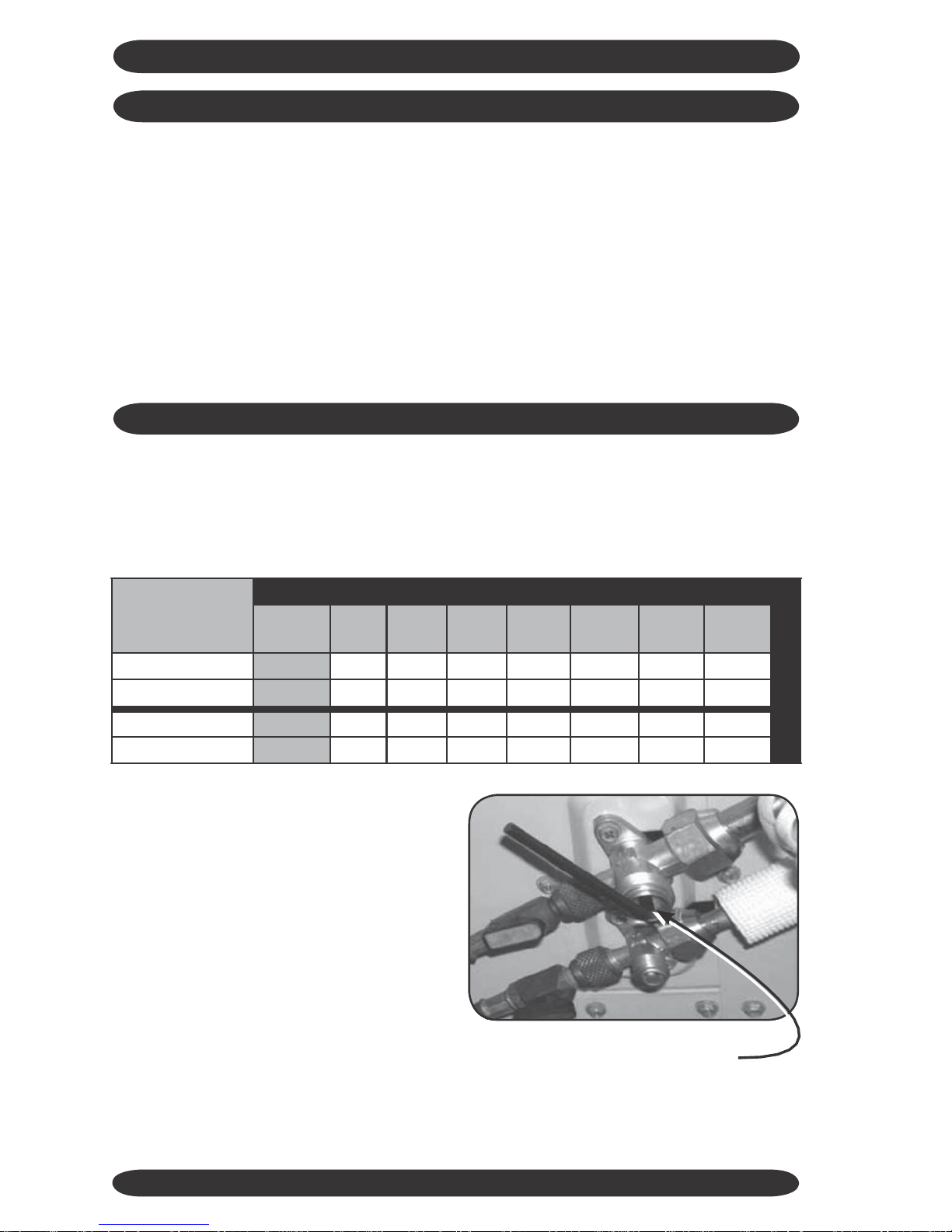
SYSTEM START UP
The condenser is charged with enough
R410Arefrigerantfor 24.6 feet of
interconnect. For longer line set lengths
additional charge must be added in per the
following table.
Withtheevaporatorandlinesetcompletely
evacuated the system can now be opened
to allow the refrigerant charge in the out-
door unit to be released into the line set.
The service valves require a 6mm and a
5mm Allen wrench respectively to undo
the valve stems. Remove the brass caps
from the service valves. Open the suc-
tion line valve first to prevent any pos-
sible oil logging of the capillary tube ex-
pansion device that can occur if the liquid
line valve is opened first with the rest of
the system in a deep vacuum. Then open
the “Liquid or Expanded Gas” line.
Unscrew both valve stems until they come
to a stop against the valve body, replace
the brass caps, then tighten the caps to
prevent leaks. Energize the breaker to al-
low system to be powered.
Open the suction line valve first
Continued next page.
14
UNIT
LINE
SET
AND
ADDED
CHARGE
REQUIRED
Charge
oz.
per
ft.
20
ft.
25
ft.
30
ft.
35
ft.
40
ft.
45
ft.
50
ft.
CHARGE
HF-25/HF-35
.3oz./ft.
1.2
oz.
2.7
oz.
4.2
oz.
5.7
oz.
N/A
N/A
N/A
HF-51/HF-70
.6oz./ft.
2.4
oz.
5.4
oz.
8.4
oz.
11.4
oz.
14.4
oz.
17.4
oz.
20.4
oz.
HFR-25/HFR-35
.3oz./ft.
1.2
oz.
2.7
oz.
4.2
oz.
5.7
oz.
N/A
N/A
N/A
HFR-51/HFR-70
.6oz./ft.
2.4
oz.
5.4
oz.
8.4
oz.
11.4
oz.
14.4
oz.
17.4
oz.
20.4
oz.
HARBOR POINT WALL SPLIT DUCTLESS SYSTEMS
Start the
indoor
unit,
cooling
mode
is
only
allowed
when
the outside ambient
temperature
is
above
60° F to prevent
damage
to the
compressor
. Unit
has
a
3
minute time
delay
before the
compressor
start
up
operation.
Note: If interconnect
is
less
then
24.6
feet
a
small
amount of refrigerant
may need
to
be
reclaimed
to
achieve
the
proper
charge
for optimal
operation. Harbor Point
recommends
fine
tuning
using
the “Superheat”
method.
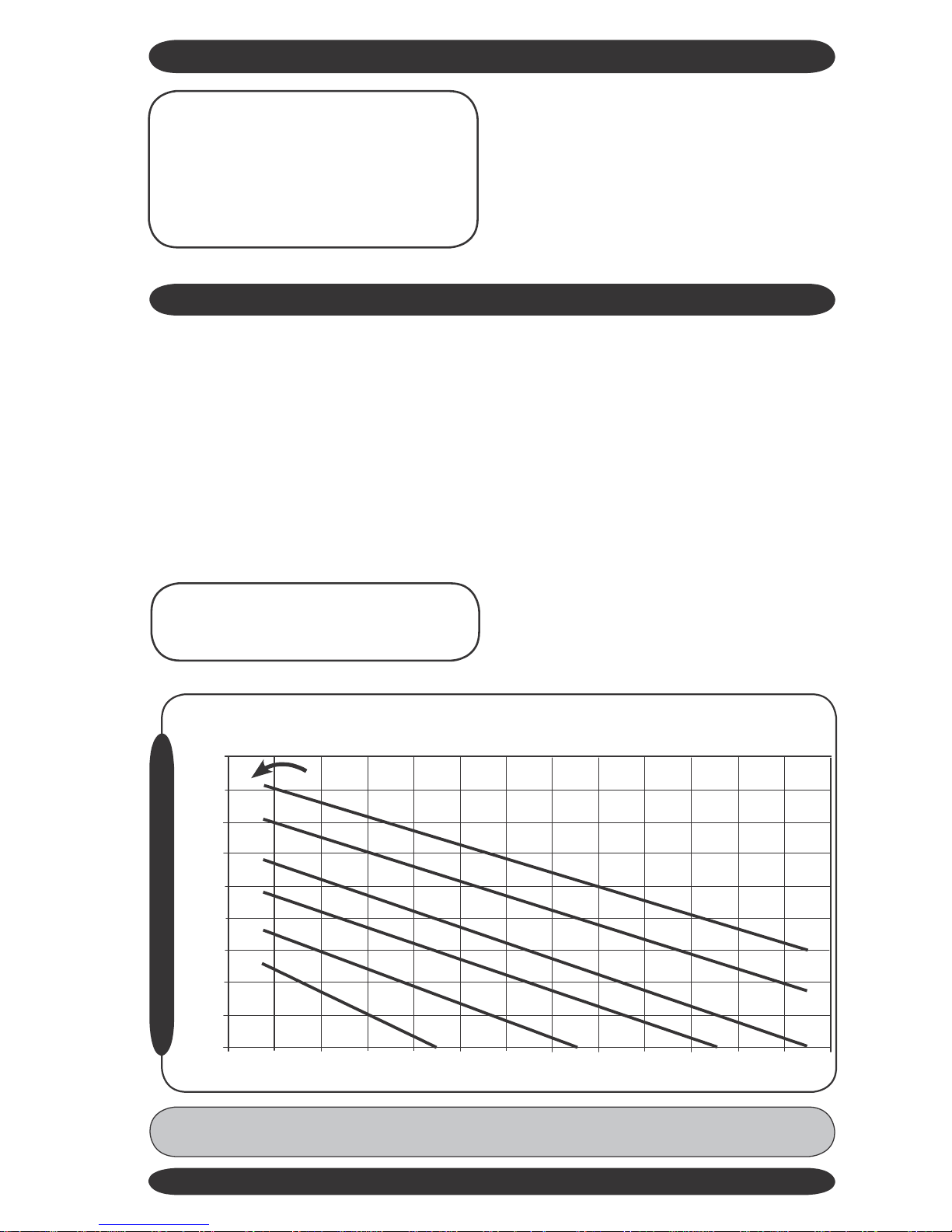
FIELD CHARGING
Forpropersuperheatreadings,a standard
low-side refrigerant gauge and an accurate
thermometer is needed. A mercury or
stem-type thermometer is not adequate
for suction-line temperatures. We recom-
mend electric thermocouple thermometers
(available at most refrigeration wholesal-
ers); however an accurate remote-bulb
thermometer can be used. When measur-
ing the line temperature, be sure the ther-
mometer is securely attached to assure
accurate measurements. The chart below
gives superheat values at various outdoor
temperatures.Allowatleast 5 minutes run-
ning time between charge adjustments for
the unit to stabilize.
The use of the superheat method is highly
recommended for field charging or check-
ing the existing refrigerant charge in a
systemthatisinthecoolingcycle.Because
each installation is different in terms of
indoor air flow, refrigerant line length, etc..,
the factory charge may not be correct
for every application. To assure the best
performance from the air-conditioner, the
refrigerant charge should be checked and
adjusted, if need be, on each installation.
Note:Refrigerantsuperheatisthetem-
peratureabove thesuctionpressureat
its saturation temperature.
SUPERHEA
T
CHAR
GING
CHAR
T
Chart based on
360
to
400
CFM/ton indoor air flow and
50%
relative humidity
Use
on
systems
that cool with capillary or piston
50
Indoor dry bulb temperature
45
40
90
35
30
25
20
15
10
5
55
60
65
70
75
80
85
90
95
100
105
OUTDOOR TEMPERATURE °F
110
115
Note: If operating superheat ismore than 5° F above the chart value, add refrigerant. If
below the chart value remove refrigerant. If below the limit line, remove refrigerant.
15
SUPERHEAT CHARGING CHART
SUPERHEAT °F
95
°F
85
80
75
70

HARBOR POINT WALL SPLIT DUCTLESS SYSTEMS
FIELD CHARGING
Instructions:
1. Measure suction pressure and deter-
mine evaporator-refrigeranttemperature
on R410A scale of low-side gauge.
2. Measure suction-line temperature on
suction line of the unit.
3. Measure outdoor and indoor tempera-
tures.
4. Determine from the table what the
superheat should be for the indoor and
outdoor temperatures.
5.Adjust charge if needed. Be sure unit is
running at stabilized condition.
Example of typical system operations:
Note:
When the system is in heat cycle, the refriger-
ant charge is checked by using the liquid sub-
cool method. Liquid sub-cool is the temperature
below the high side pressure at its saturation
temperature.
16
Cooling Cycle
Conditions
80°F DB/50% RH Indoors
82°F DB Outdoors
Return Gas Psig
140 (49° F Saturated Temperature)
Superheat
Refer to supplied superheat chart (16° F)
Heat Cycle
Conditions
70° F Indoors
47° F Outdoors
High Side Gas Psig
350/375 (107/112° F Saturated Temperature)
Sub-Cooling
10 - 15° F

OPERATION SECTION FOR
HF-25/HF-35 & HFR-25
/HFR-35
OPERATION AND MAINTENANCE SECTION FOR HF-51/HF-70 & HFR-51/HFR-70 model follows this section.
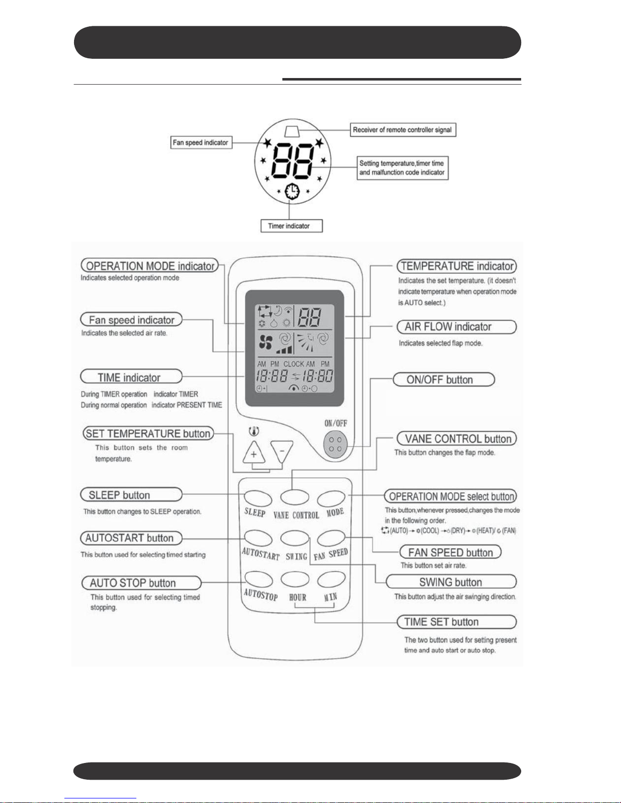
Guide
to
features
and
their
function
There are many models, features and appearance will vary. The figure shown is
representative of the operation of
9,000/12,000 Btuh systems.
Note: Do not open the grille at an angle over 60 degrees.
17
Lightly push both sides of the air inlet grille at the
botton and pull it to this side till a resistance is felt.
Push down the air inlet grille and the push both sides of air inlet
grille at the bottom.
Air return grill
Takes in the indoor air
OPERATION SECTION FOR
HF-25/HF-35 & HFR-25
/HFR-35
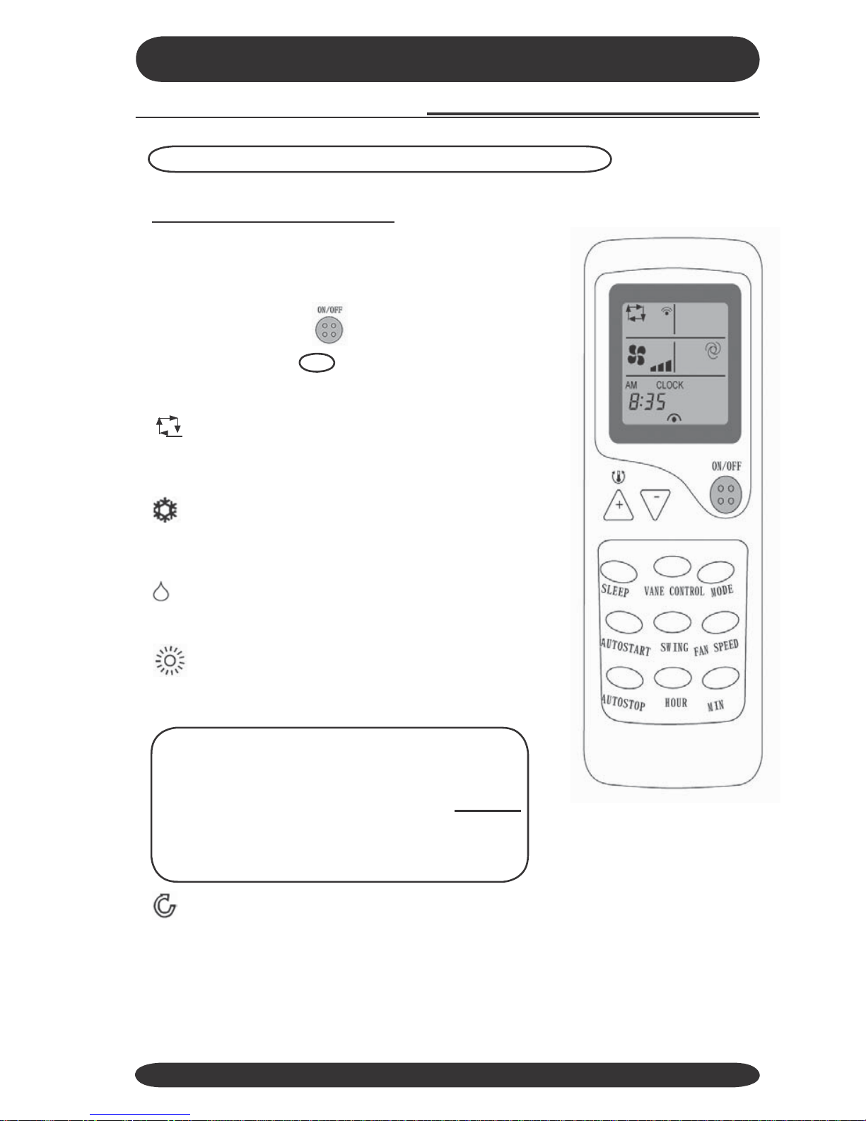
R
emote
Control Operation
18
This button, when pressed, starts operation
and stops when pressed again.
OPERATION SECTION FOR
HF-25/HF-35 & HFR-25
/HFR-35
R
emote
Control Operation
Note: Wait 3 minutes before restarting the unit.
Selecting
MODE
of
OPERATION
To select operating mode, point the remote control
toward the indoor air conditioning unit:
1) Press the ON/OFF
button to START.
2) Press the MODE
operating modes:
button to step through the
AUTO MODE –automatically operates the sys-
tem in DRY, COOL ,or HEAT mode depending on
the indoor temperature and setting.
COOL MODE –operates the system in COOL
mode depending on the indoor temperature and set
point.
DRY MODE –operates the system in DEHUMIDI-
FICATIONmode.
HEAT MODE –operates the system in HEAT
mode depending on the indoor temperature and set
point.
Important:
Heating operation will cease at approximately
15° F outdoor temperature due to a sensor lo-
cated in the outdoor unit. This product does
not
contain supplemental electric heat, therefore
other means of heat need to used when this sys-
tem ceases operation at low outdoor ambients.
FAN MODE –runs the FAN to circulate the air.
3) Press the ON/OFF button again to STOP.
19

OPERATION SECTION FOR
HF-25/HF-35 & HFR-25
/HFR-35
R
emote
Control Operation
Temperature
adjustment
in
AUTO
SELECT
mode
To adjust the air temperature during AUTO SELECT
mode, point the remote control toward the indoor air
conditioning unit:
1) Press the
button once. To raise the set point
temperature 1°C or 1°F.
2) Press the button once, to reduce the set
point temperature 1°C or 1°F.
COOL/HEAT
&
FAN/DRY
mode
Point the remote control toward the indoor air condition-
ing unit:
1) Press the ON/OFF
button.
2) Press the MODE
button, select the mode of
operation; COOL, DRY, HEAT/FAN or AUTO.
3) Press the
perature.
or to set the desired tem-
Once minimum or maximum setting is reached
operation will be continued by
pressing
or
4) Press the FAN SPEED
sired air flow rate.
button to set the de-
Press the ON/OFF
button again to stop.
Notes:
• In the COOLING-ONLY operation, the HEAT
mode will disable, and it will go to FAN mode.
•The settings can be changed even while the air
conditioner is off.
20
Heat
Cool
64°F- 88°F
(16°C-31°C)
64°F- 88°F
(16°C-31°C)
This manual suits for next models
6
Table of contents
Other Harbor Point Air Conditioner manuals

Harbor Point
Harbor Point HP9CP User manual

Harbor Point
Harbor Point HS-25V1A-M88AH1 User manual

Harbor Point
Harbor Point HS-26H1A-M88AH1 User manual

Harbor Point
Harbor Point HF-25GW General instructions

Harbor Point
Harbor Point HP12CP User manual

Harbor Point
Harbor Point HSG-09CRN1 User manual

Harbor Point
Harbor Point HS9A series User manual

 Operation manual")


