Harbor Point HSG-09CRN1 User manual

NOTE:
Please read this rst before servicing the unit.
If you have any problems, always contact your service center rst.
Service Manual
Room Air Conditioner
Split Wall-Mounted Type
Applies to:
HSG-09CRN1
HSG-12CRN1
HSG-18CRN1
HSG-24CRN1
HSG-09HRN1
HSG-12HRN1
HSG-18HRN1
HSG-24HRN1

Content
- 1 -
Content
1
Precaution....................................................................................................................1
1.1 Safety Precaution...................................................................................................................................1
1.2 Warning..................................................................................................................................................1
1.3 Function .................................................................................................................................................4
2
Dimension....................................................................................................................5
3
Specification ................................................................................................................7
4
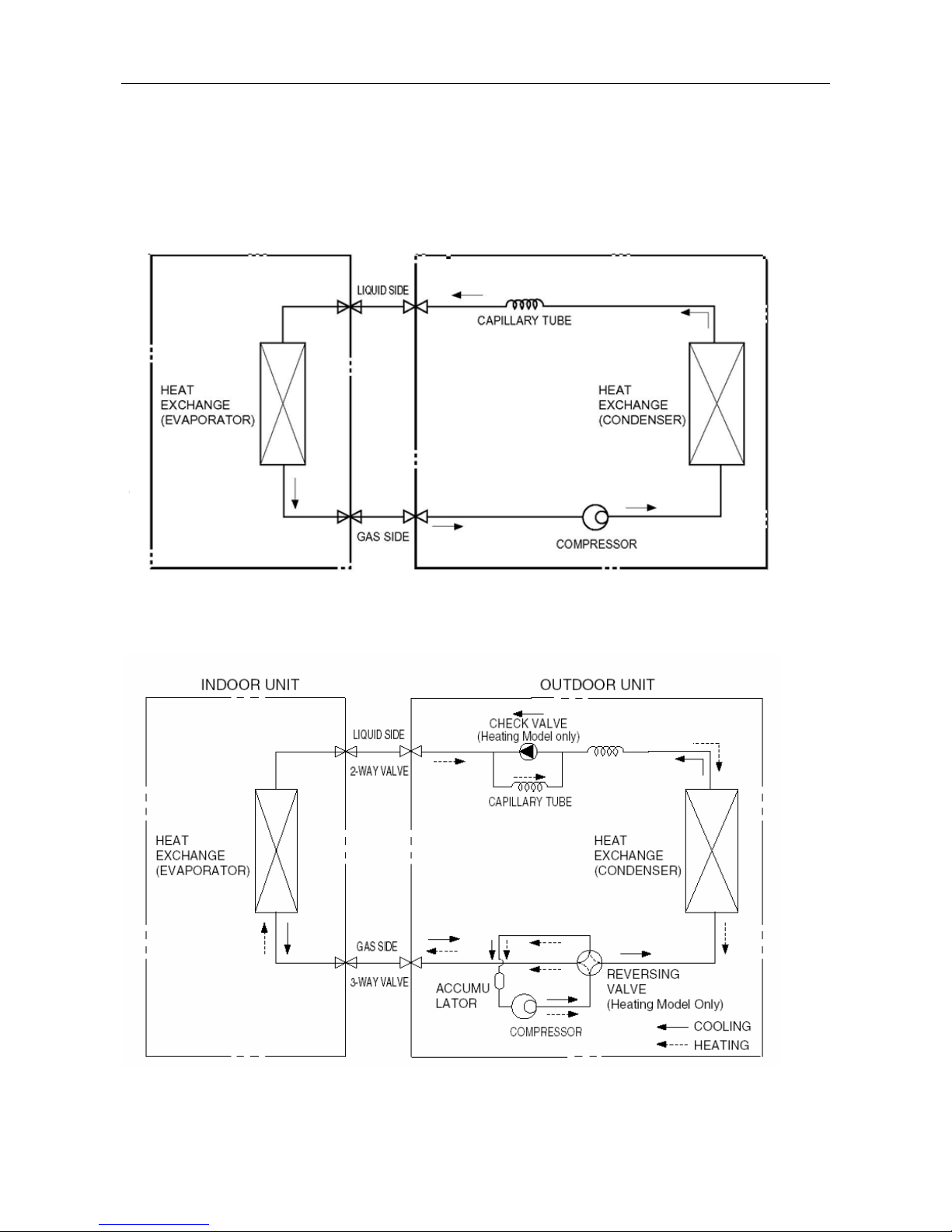
Refrigerant cycle diagram.........................................................................................12
5
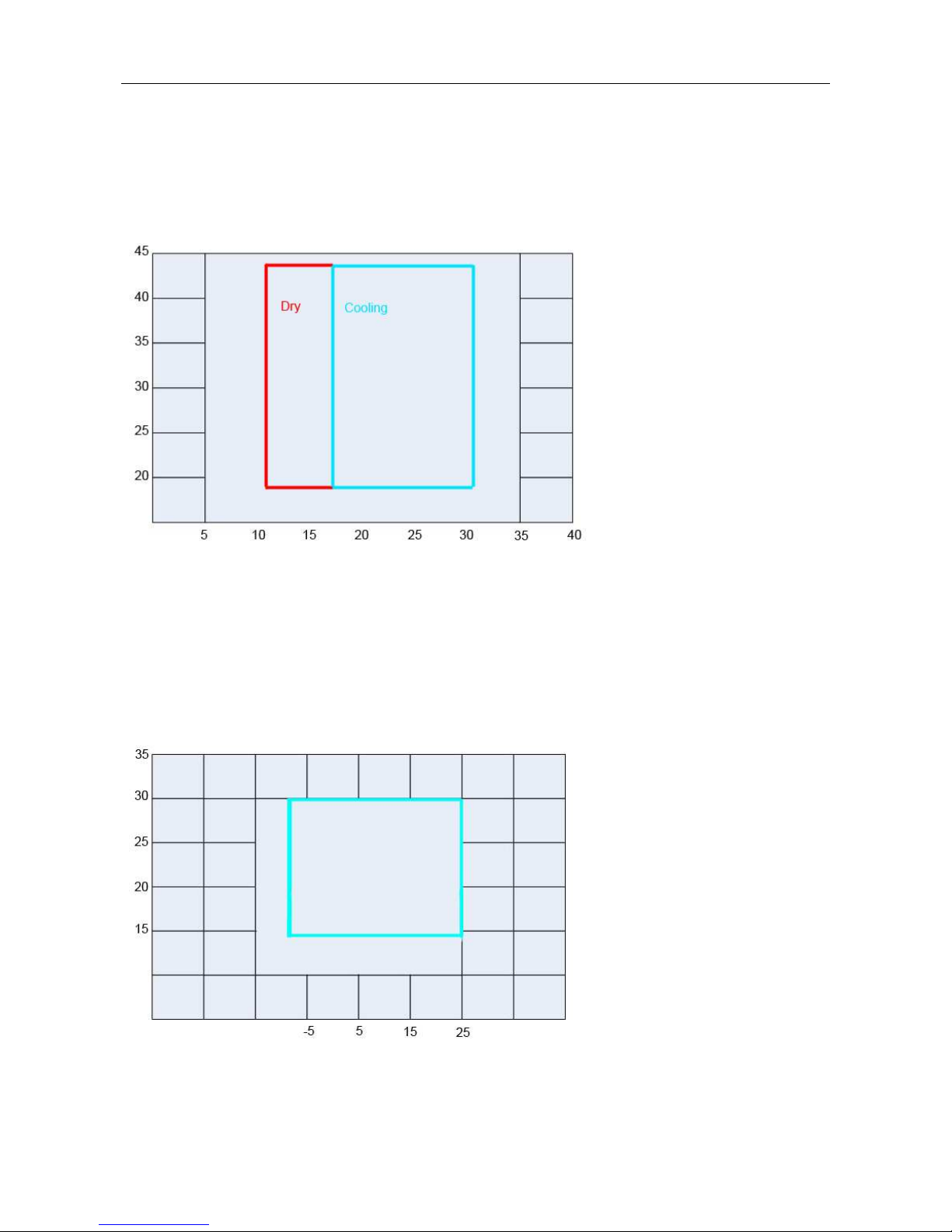
Operation limits .........................................................................................................13
6
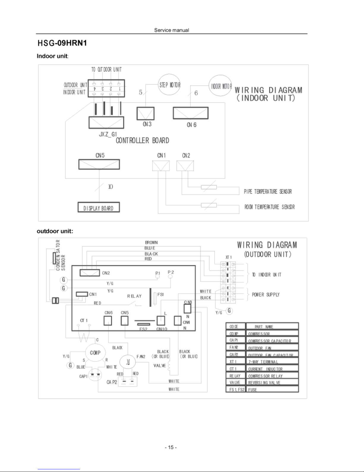
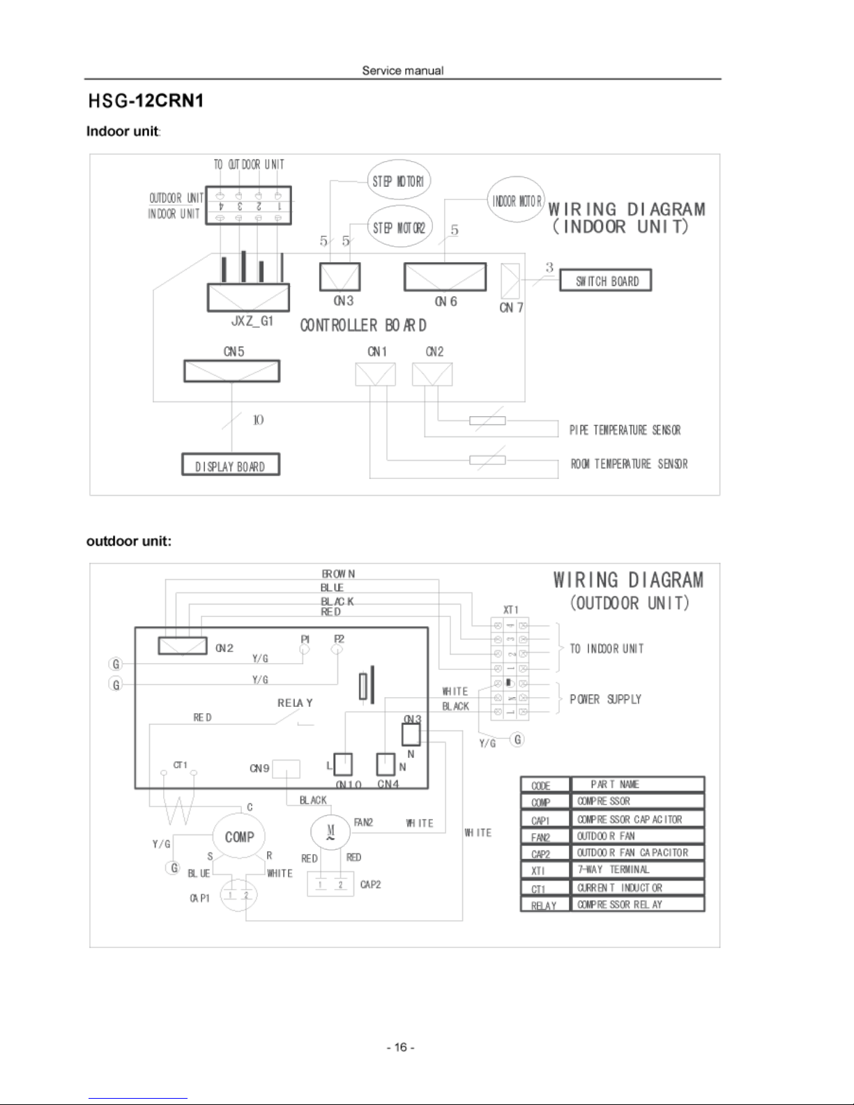
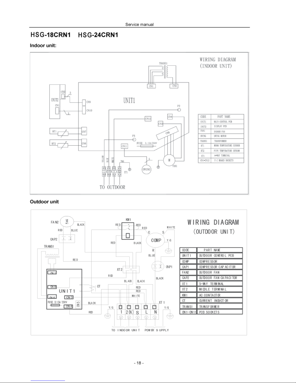
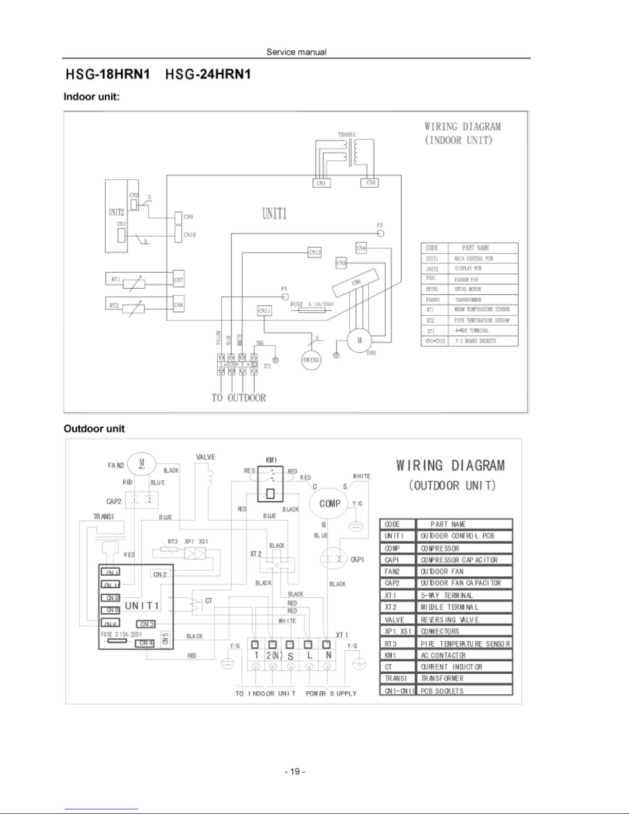
Wiring diagram...........................................................................................................14
7
Installation details......................................................................................................20
7.1 Wrench torque sheet for installation....................................................................................................20
7.2 Connecting the cables .........................................................................................................................20
7.3 Pipe length and the elevation ..............................................................................................................20
7.4 Air purging of the piping and indoor unit..............................................................................................21
7.5 Pumping down (Re-installation)...........................................................................................................23
7.6 Re-air purging (Re-installation)............................................................................................................24
7.7 Balance refrigerant of the 2-way, 3-way valves...................................................................................25
7.8 Evacuation ...........................................................................................................................................26
7.9 Gas charging........................................................................................................................................27
8
Electronic function....................................................................................................28
8.1 Electronic control working environment...............................................................................................28
8.2 Proper symbols and their meaning......................................................................................................28
8.3 Function ...............................................................................................................................................29
8.4 Protection.............................................................................................................................................29
8.5 Fan only mode.....................................................................................................................................30
8.6 Cooling mode.......................................................................................................................................30
8.7 Dehumidifying mode............................................................................................................................31
8.8 Heating mode.......................................................................................................................................31
8.9 Defrosting mode(available for heating mode) .....................................................................................32
8.10 Auto mode..........................................................................................................................................33
8.11 Force cooling function........................................................................................................................33
8.12 Sleep mode........................................................................................................................................34
8.13 Auto restart function........................................................................................................................... 35
9
Model and Parameters ..............................................................................................36
10
Troubleshooting.........................................................................................................38
10.1 Display board.....................................................................................................................................38
10.2 Troubleshooting .................................................................................................................................39
10.3 Diagnostic chart.................................................................................................................................40
10.4 Resetting phenomenon often occurs during operation......................................................................42
10.5 Operation lamp flashes and Timer lamp off.......................................................................................42
10.6 Operation lamp flashes and Timer lamp on.......................................................................................43
10.7 Operation lamp off and Timer lamp flashes.......................................................................................43

Content
- 2 -
10.8 Operation lamp on and Timer lamp flashes.......................................................................................43
10.9 Operation lamp flashes, Timer lamp flashes ....................................................................................43
11
Characteristic of temperature sensor......................................................................44

Service manual
- 1 -
1 Precaution
1.1 Safety Precaution
To prevent injury to the user or other people and property damage, the following instructions
must be followed.
Incorrect operation due to ignoring instruction will cause harm or damage.
Before service unit, be sure to read this service manual at first.
1.2 Warning
Installation
Do not use a defective or underrated circuit breaker. Use this appliance on a dedicated
circuit.
There is risk of fire or electric shock.
For electrical work, contact the dealer, seller, a qualified electrician, or an Authorized service
center.
Do not disassemble or repair the product, there is risk of fire or electric shock.
Always ground the product.
There is risk of fire or electric shock.
Install the panel and the cover of control box securely.
There is risk of fire of electric shock.
Always install a dedicated circuit and breaker.
Improper wiring or installation may cause fore or electric shock.
Use the correctly rated breaker of fuse.
There is risk of fire or electric shock.
Do not modify or extend the power cable.
There is risk of fire or electric shock.
Do not install, remove, or reinstall the unit by yourself (customer).
There is risk of fire, electric shock, explosion, or injury.
Be caution when unpacking and installing the product.
Sharp edges could cause injury, be especially careful of the case edges and the fins on the condenser and
evaporator.
For installation, always contact the dealer or an Authorized service center.
There is risk of fire, electric shock, explosion, or injury.
Do not install the product on a defective installation stand.
It may cause injury, accident, or damage to the product.
Be sure the installation area does not deteriorate with age.
If the base collapses, the air conditioner could fall with it, causing property damage, product failure, and personal
injury.
Do not let the air conditioner run for a long time when the humidity is very high and a door or
windows is left
open.
Moisture may condense and wet or damage furniture.
Take care to ensure that power cable could not be pulled out or damaged during operation.
There is risk of fire or electric shock.

Service manual
- 2 -
Do not place anything on the power cable.
There is risk of fire or electric shock.
Do not plug or unplug the power supply plug during operation.
There is risk of fire or electric shock.
Do not touch (operation) the product with wet hands.
There is risk of fire or electric shock.
Do not place a heater or other appliance near the power cable.
There is risk of fire and electric shock.
Do not allow water to run into electric parts.
It may cause fire, failure of the product, or electric shock.
Do not store or use flammable gas or combustible near the product.
There is risk of fire or failure of product.
Do not use the product in a tightly closed space for a long time.
Oxygen deficiency could occur.
When flammable gas leaks, turn off the gas and open a window for ventilation before turn the
product on.
Do not use the telephone or turn switches on or off.
There is risk of explosion or fire.
If strange sounds, or small or smoke comes from product. Turn the breaker off or disconnect
the power
supply
cable.
There is risk of electric shock or fire.
Stop operation and close the window in storm or hurricane. If possible, remove the product
from the window before the hurricane arrives.
There is risk of property damage, failure of product, or electric shock.
Do not open the inlet grill of the product during operation. (Do not touch the electrostatic
filter, if the unit is so equipped.
There is risk of physical injury, electric shock, or product failure.
When the product is soaked (flooded or submerged), contact an Authorized service center.
There is risk of fire or electric shock.
Be caution that water could not enter the product.
There is risk of fire, electric shock, or product damage.
Ventilate the product from time to time when operating it together with a stove, etc.
There is risk of fire or electric shock.
Turn the main power off when cleaning or maintaining the product.
There is risk of electric shock.
When the product is not be used for a long time, disconnect the power supply plug or turn off
the breaker.
There is risk of product damage or failure, or unintended operation.
Take care to ensure that nobody could step on or fall onto the outdoor unit.
This could result in personal injury and product damage.
CAUTION
Always check for gas (refrigerant) leakage after installation or repair of product.
Low refrigerant levels may cause failure of product.
Install the drain hose to ensure that water is drained away properly.
A bad connection may cause water leakage.
Keep level even when installing the product.
To avoid vibration of water leakage.
Do not install the product where the noise or hot air from the outdoor unit could damage the
neighborhoods.
It may cause a problem for your neighbors.

Service manual
- 3 -
Use two or more people to lift and transport the product.
Avoid personal injury.
Do not install the product where it will be exposed to sea wind (salt spray) directly.
It may cause corrosion on the product. Corrosion, particularly on the condenser and evaporator fins, could cause
product malfunction or inefficient operation.
Operational
Do not expose the skin directly to cool air for long periods of time. (Do not sit in the draft).
This could harm to your health.
Do not use the product for special purposes, such as preserving foods, works of art, etc. It is
a consumer air conditioner, not a precision refrigerant system.
There is risk of damage or loss of property.
Do not block the inlet or outlet of air flow.
It may cause product failure.
Use a soft cloth to clean. Do not use harsh detergents, solvents, etc.
There is risk of fire, electric shock, or damage to the plastic parts of the product.
Do not touch the metal parts of the product when removing the air filter. They are very sharp.
There is risk of personal injury.
Do not step on pr put anything on the product. (outdoor units)
There is risk of personal injury and failure of product.
Always insert the filter securely. Clean the filter every two weeks or more often if necessary.
A dirty filter reduces the efficiency of the air conditioner and could cause product malfunction or damage.
Do not insert hands or other object through air inlet or outlet while the product is operated.
There are sharp and moving parts that could cause personal injury.
Do not drink the water drained from the product.
It is not sanitary could cause serious health issues.
Use a firm stool or ladder when cleaning or maintaining the product.
Be careful and avoid personal injury.
Replace the all batteries in the remote control with new ones of the same type. Do not mix old
and mew batteries or different types of batteries.
There is risk of fire or explosion.
Do not recharge or disassemble the batteries. Do not dispose of batteries in a fire.
They may burn of explode.
If the liquid from the batteries gets onto your skin or clothes, wash it well with clean water. Do
not use the remote of the batteries have leaked.
The chemical in batteries could cause burns or other health hazards.

Service manual
- 4 -
1.3 Function
Indoor unit
1. Operation ON/OFF by remote controller
2. Sensing by room temperature
Room temperature sensor. Pipe temperature
sensor.
3. Room temperature control
Maintain the room temperature in accordance with
the setting temperature.
4. Starting temperature control
Indoor fan is delayed for 5 sec at the starting.
5. Time Delay Safety control
Restarting is for approx. 3 minutes.
6. Indoor fan speed control
High, med, low, breeze.
7. Operation indication Lamps (LED)
Light up in the LED for each operation mode.
8. Two-direction air vane
The unit will decide the louver direction according
to operation mode.
9. Sleep mode auto control
The fan is turn to low speed (cooling/heating).
The unit will be turn off after seven hours.
10. Independent dehumidification
The function is usually used in rainy days in
springtime or damp areas
11. Self-diag. function
The function will be operate in any operation mode.
12. Air flow Direction control
The louver can be set at the desired position or
swing up and down automatically
13. Auto mode
The unit can be change by the room temperature.
14. Anti-cold function
Prevent the cold wind at the beginning of unit start.
15. Temp. Compensation
16. Defrost mode
17. Auto-restart function
18. Flexible wiring connection
19. Easy clean panel
Outdoor unit
1. Power relay control
The unit has 3 mins delay between continuously
ON/OFF operations.
2. Low noise air flow system
Bird tail propeller fan makes the outdoor unit run
more quietly
3. Hydrophilic aluminum fin
For the cooling & heating mode only.
The hydrophilic fin can improve the heating
efficiency at operation mode.
4. 4 way valve control
It is only operated in the heating operation mode
except defrosting operation.
5. Anti-rust cabinet
Made from electrolytic zinc steel sheet and anti-rust
coated components.
6. Valve protection cover
It protects the valves and prevents water from
dripping.

Service manual
- 5 -
2 Dimension
Indoor unit
Dimension
Mode W H D
9K 815 280 195
12K 906 286 235
18K 1250 325 230
24K 1250 325 230

Service manual
- 6 -
outdoor unit
Dimension
Mode W H D L1 L2
9K 780 540 250 549 266
12K 760 590 285 530 290
18K 845 695 335 560 335
24K 895 860 330 590 333

Service manual
- 12 -
4 Refrigerant cycle diagram
Cooling only
Heat pump mode

Service manual
- 13 -
5 Operation limits
Cooling operation
Outdoor unit air temp. DB℃
Indoor air temp. DB℃
Note: The chart is the result from the continuous operation under constant air temperature
conditions. However, excludes the initial pull-down stage.
Heating operation
Indoor air temp. ℃DB
Outdoor unit air temp.℃DB
Note: The chart is the result from the continuous operation under constant air temperature
conditions. However, excludes the initial pull-down stage.


Service manual
- 20 -
7 Installation details
7.1 Wrench torque sheet for installation
Torque
mm inch Kg.m
φ6.35 1/4 1.8
φ9.52 3/8 4.2
φ12.7 1/2 5.5
φ15.88 5/8 6.6
φ19.05 3/4 6.6
Outside diameter
7.2 Connecting the cables
The power cord of connect should be selected according to the following specifications sheet.
Amp 10 15 20
mm
2
1.0 1.5 2.5
Grade
7.3 Pipe length and the elevation
Standard
length Max. Max. Additional
(m) Elevation Elevation refrigerant
Btu/h GAS LIQUID B (m) A (m) (g/m)
3/8’’ (φ9.52) 1/4’’ (φ6.35) 5 5 10 30
1/2’’ (φ12.7) 1/4’’ (φ6.35) 5 5 10 30
1/2’’ (φ12.7) 1/4’’ (φ6.35) 5 8 15 30
5/8’’ (φ15.88) 1/4’’ (φ6.35) 5 10 20 30
5/8’’ (φ15.88) 3/8’’ (φ9.52) 5 10 20 65
5/8’’ (φ15.88) 3/8’’ (φ9.52) 5 15 30 65
3/4’’ (φ19.05) 3/8’’ (φ9.52) 5 15 30 65
Pipe size
7k~12K
16K~28K
30K~36K
Capacity

Service manual
- 21 -
Caution:
Capacity is base on standard length and maximum allowance length is base of reliability.
Oil trap should be install per 5-7 meters.
7.4 Air purging of the piping and indoor unit
Required tools:
Hexagonal wrench; adjustable wrench; torque wrenches, wrench to hold the joints and gas leak
detector.
Note:
The air in the indoor unit and in the piping must be purged. If air remains in the refrigeration
piping, it will affect the compressor, reduce the cooling capacity, and could lead to a malfunction
of unit.
Be sure, using a torque wrench to tighten the service port cap (after using the service port), so
that it prevents the gas leakage from the refrigeration cycle.
In case that more
than 5m.

Service manual
- 22 -
Procedure:
::
:
1. Recheck the piping connections.
2. Open the valve stem of the 2-way valve counterclockwise approximately 90’, wait 10 seconds, and
then set it to closed position.
Be sure to use a hexagonal wrench to operate the valve stem
3. Check for gas leakage.
Check the flare connection for gas leakage
4. Purge the air from the system.
5. Set the 2-way valve to the open position and remove the cap from the 3-way valve’s service port.
6. Using the hexagonal wrench to press the valve core pin, discharge for three seconds and then wait
for one minute.
7. Use torque wrench to tighten the service port cap to a torque of 1.8 kg.m. (18n.m)
8. Set the 3-way valve to the opened position.
9. Mounted the valve stem nuts to the 2-way and 3-way valves.
10. Check for gas leakage.
11. At this time, especially check for gas leakage from the 2-way and 3-way stem nuts, and from
the service port.
Caution:
If gas leakage is discovered in step (3) above, take the following measures.
If the leaks stop when the piping connections are tightened further, continue working from
step (4).
If the gas leaks do not stop when the connections are retightened, repair the location of the
leak, discharge all of the gas through the service port, and then recharge with the specified
amount of gas from a gas cylinder.
This manual suits for next models
7
Table of contents
Other Harbor Point Air Conditioner manuals

Harbor Point
Harbor Point HS9A series User manual

Harbor Point
Harbor Point HS-25V1A-M88AH1 User manual

Harbor Point
Harbor Point HP9CP User manual

Harbor Point
Harbor Point HF-25GW/GX1b Technical Document

Harbor Point
Harbor Point HS-26H1A-M88AH1 User manual

Harbor Point
Harbor Point HF-25GW General instructions

Harbor Point
Harbor Point HP12CP User manual
Popular Air Conditioner manuals by other brands

York
York YUHA 18 FS Service manual

Hisense
Hisense AUC-18UX4SGAA Instruction and installation manual

MegaLife
MegaLife NEBULA GREEN R32 Use and Installation Instructions

air choice
air choice TY-EA-03 user manual

Daikin
Daikin RXYQ72PAYD installation manual

Technibel
Technibel KPAFP125R5IA Series instruction manual