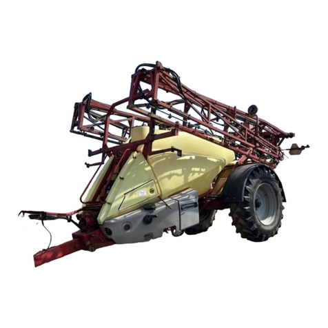
Hardi COMMANDER Classic DELTA User manual

COMMANDER
Classic DELTA
www.hardi-international.com
67002600 - Version 1.02
GB - 12.2005
Instruction book

Illustrations, technical information and data in this book are to the best of our belief correct at the time of prin-
ting. As it is HARDI INTERNATIONAL A/S policy permanently to improve our products, we reserve the right to
make changes in design, features, accessories, specifications and maintenance instructions at any time and wit-
hout notice.
HARDI INTERNATIONAL A/S is without any obligation in relation to implements purchased before or after such
changes.
HARDI INTERNATIONAL A/S cannot undertake any responsibility for possible omissions or inaccuracies in this
publication, although everything possible has been done to make it complete and correct.
As this instruction book covers more models and features or equipment, which are available in certain countri-
es only, please pay attention to paragraphs dealing with precisely your model.
Published and printed by HARDI INTERNATIONAL A/S
We congratulate you for choosing a HARDI plant protection product. The reliabi-
lity and efficiency of this product depend upon your care. The first step is to
carefully read and pay attention to this instruction book. It contains essential
information for the efficient use and long life of this quality product.
As this instruction book covers all versions of the equipment, including all hyd-
raulic boom versions, and all operating units, please pay attention to the para-
graphs dealing with precisely your model.
This book is to be read in conjunction with the “Spray Technique” book.

Table of contents
TOC. 1
Table of contents
1 - CE Declaration
Declaration of Conformity ...........................................................................................................................1
2 - Safety notes
Operator safety ............................................................................................................................................1
General info ....................................................................................................................................1
3 - Description
General info..................................................................................................................................................1
View.......................................................................................................................................................................................................................................1
Identification plates.....................................................................................................................................................................................................1
Identification plates.....................................................................................................................................................................................................2
Roadworthiness .............................................................................................................................................................................................................2
Sprayer use........................................................................................................................................................................................................................3
Frame....................................................................................................................................................................................................................................3
Tank........................................................................................................................................................................................................................................3
Liquid system ...............................................................................................................................................4
General info - MANIFOLD system.......................................................................................................................................................................4
Diagram - Smart Valve system..............................................................................................................................................................................5
Pump ....................................................................................................................................................................................................................................5
Valves and symbols .....................................................................................................................................................................................................5
Valves and symbols .....................................................................................................................................................................................................5
Green valves - Green disc = Pressure valve..................................................................................................................................................6
Black valves - Black disc = Suction valve........................................................................................................................................................6
Agitation valve................................................................................................................................................................................................................6
Electrical operated MANIFOLD valves (optional equipment) ..........................................................................................................7
Self-cleaning filter.........................................................................................................................................................................................................7
HARDI FILLER ...................................................................................................................................................................................................................8
Control unit ......................................................................................................................................................................................................................8
EVC control unit.............................................................................................................................................................................................................8
Boom ............................................................................................................................................................9
Boom and terminology ............................................................................................................................................................................................9
Equipment..................................................................................................................................................10
Driving technique for STEER and SELF TRACK.........................................................................................................................................10
STEER TRACK (optional)..........................................................................................................................................................................................10
SELF TRACK.....................................................................................................................................................................................................................10
AUTO TRACK..................................................................................................................................................................................................................10
Platform............................................................................................................................................................................................................................11
Tank level indicator...................................................................................................................................................................................................11
Remote pressure gauge ........................................................................................................................................................................................11
Mudguards (optional equipment)..................................................................................................................................................................12
Stop wedges (optional equipment) ..............................................................................................................................................................12

Table of contents
TOC. 2
4 - Sprayer setup
General info..................................................................................................................................................1
Unloading the sprayer from the truck.............................................................................................................................................................1
Before putting the sprayer into operation....................................................................................................................................................1
Support leg.......................................................................................................................................................................................................................1
Jack up the sprayer......................................................................................................................................................................................................2
Mechanical connections ...............................................................................................................................3
Drawbars - Mounting the drawbar extension............................................................................................................................................3
Transmission shaft - Operator’s safety .............................................................................................................................................................3
Transmission shaft - Installation ..........................................................................................................................................................................4
Hose package support..............................................................................................................................................................................................5
SELF TRACK .......................................................................................................................................................................................................................5
Fixed drawbar..................................................................................................................................................................................................................6
STEERING drawbar transport lock (optional equipment)....................................................................................................................6
Hydraulic systems ........................................................................................................................................7
General info......................................................................................................................................................................................................................7
Requirements - tractor (LPY model) .................................................................................................................................................................7
Requirements - tractor (LPZ model) .................................................................................................................................................................7
Open centre hydraulics (optional equipment)..........................................................................................................................................8
Electrical connections...................................................................................................................................9
Power supply...................................................................................................................................................................................................................9
Control boxes..................................................................................................................................................................................................................9
Installation of control unit brackets ..................................................................................................................................................................9
Installation of control box - EVC control unit .............................................................................................................................................9
Road safety kit..............................................................................................................................................................................................................10
Pendulum lock setup on LPY model.............................................................................................................................................................10
Liquid system .............................................................................................................................................11
Self-cleaning filter - Choice of restrictor......................................................................................................................................................11
Track gauge, axles and wheels...................................................................................................................12
Altering the track gauge .......................................................................................................................................................................................12
Transport....................................................................................................................................................13
General info ...................................................................................................................................................................................................................13
Transport lock...............................................................................................................................................................................................................13
Transport brackets.....................................................................................................................................................................................................14
Boom ..........................................................................................................................................................15
Pendulum setup .........................................................................................................................................................................................................15
Boom folding speed adjustment - LPY only.............................................................................................................................................15
Slanting the boom....................................................................................................................................................................................................16
Pendulum effect adjustment..............................................................................................................................................................................16
Parallel setting of lift and frame........................................................................................................................................................................17
Brakes.........................................................................................................................................................18
Emergency and parking brake (optional equipment) .......................................................................................................................18
Hydraulic activated brakes (optional equipment)................................................................................................................................18
Air activated brakes (optional equipment)................................................................................................................................................19
Single-line brakes (optional equipment)....................................................................................................................................................19
Dual-line brakes (optional equipment)........................................................................................................................................................19

Table of contents
TOC. 3
5 - Operation
Boom ............................................................................................................................................................1
Safety info..........................................................................................................................................................................................................................1
Manoeuvring of the boom - LPY........................................................................................................................................................................1
Manoeuvring of the boom - LPZ........................................................................................................................................................................2
Alternative boom width - LPZ only...................................................................................................................................................................2
Liquid system ...............................................................................................................................................3
Filling of water ................................................................................................................................................................................................................3
Filling through tank lid..............................................................................................................................................................................................3
Suction filling device (optional equipment) ...............................................................................................................................................3
Fast filling device (optional equipment)........................................................................................................................................................4
Filling device and Fast filling device used simultaneously (optional equipment)..............................................................5
Quick coupler for external filling (optional equipment)......................................................................................................................5
Filling of rinsing tank (optional equipment)................................................................................................................................................6
Filling of clean water tank (optional equipment).....................................................................................................................................6
Adjustment of EVC operating unit ....................................................................................................................................................................7
Safety precautions - crop protection chemicals.......................................................................................................................................7
Filling chemicals through tank lid......................................................................................................................................................................8
Filling Liquid chemicals by HARDI FILLER .....................................................................................................................................................8
Filling Powder chemicals by HARDI FILLER..................................................................................................................................................9
Operating the control unit while spraying................................................................................................................................................10
Quick reference ...........................................................................................................................................................................................................11
Cleaning .....................................................................................................................................................12
General info ...................................................................................................................................................................................................................12
Cleaning the tank and liquid system.............................................................................................................................................................13
Cleaning and maintenance of filters .............................................................................................................................................................13
Use of rinsing tank and rinsing nozzles (optional equipment) ....................................................................................................14
Technical residue........................................................................................................................................................................................................16
Using the drain valve...............................................................................................................................................................................................16
Spray Technique - see separate book...........................................................................................................................................................16
Optional extras - see separate books............................................................................................................................................................16

Table of contents
TOC. 4
6 - Maintenance
Lubrication ...................................................................................................................................................1
General info......................................................................................................................................................................................................................1
Recommended lubricants ......................................................................................................................................................................................1
Boom lubrication & oiling plan............................................................................................................................................................................1
Trailer lubrication & oiling plan............................................................................................................................................................................2
Service and Maintenance intervals ..............................................................................................................4
10 hours service - Suction filter ...........................................................................................................................................................................4
10 hours service - Self-Cleaning Filter .............................................................................................................................................................4
10 hours service - In-Line filter (optional equipment) ..........................................................................................................................4
10 hours service - Nozzle filters...........................................................................................................................................................................5
10 hours service - Spraying circuit.....................................................................................................................................................................5
10 hours service - Brakes (optional equipment).......................................................................................................................................5
10 hours service - Brakes air tank (optional equipment).....................................................................................................................5
10 hours service - Retighten bolts (suspension only) ...........................................................................................................................5
50 hours service - Transmission shaft ..............................................................................................................................................................5
50 hours service - Wheel bolts and nuts .......................................................................................................................................................6
50 hours service - Air brakes..................................................................................................................................................................................6
50 hours service - Tyre pressure ..........................................................................................................................................................................6
50 hours service - Expansion bottle (SELF TRACK only).......................................................................................................................6
100 hours service - Check/adjust drawbar (Fixed drawbar only)...................................................................................................7
250 hours service - Readjustment of the boom.......................................................................................................................................7
250 hours service - Hydraulic circuit ................................................................................................................................................................7
250 hours service - Hoses and tubes...............................................................................................................................................................7
250 hours service - Wheel bearings..................................................................................................................................................................7
250 hours service - Inspect parking brake ...................................................................................................................................................8
250 hours service - Brake adjustment .............................................................................................................................................................8
250 hours service - Air brake filters (optional equipment).................................................................................................................8
250 hours service - Hydraulic brakes ...............................................................................................................................................................9
250 hours service - Expansion bottle (SELF TRACK only) ....................................................................................................................9
1000 hours service - Transmission shaft.........................................................................................................................................................9
1000 hours service - Wheel bearings and brakes..................................................................................................................................10
1000 hours service - Change of bearings between centre and inner section...................................................................12
Occasional maintenance ............................................................................................................................13
General info ...................................................................................................................................................................................................................13
Pump valves and diaphragms renewal........................................................................................................................................................13
Cone check/renewal for EVC operating unit............................................................................................................................................14
Cone check/renewal for EVC distribution valve.....................................................................................................................................14
Level indicator adjustment..................................................................................................................................................................................14
Level indicator cord renewal ..............................................................................................................................................................................15
Drain valve seal renewal........................................................................................................................................................................................15
Nozzle tubes and fittings......................................................................................................................................................................................15
Adjustment of 3-way-valve..................................................................................................................................................................................16
Readjustment boom - general info................................................................................................................................................................16
Horizontal alignment of centre and inner section...............................................................................................................................16
Vertical alignment of centre and inner section (LPY only)..............................................................................................................17
Horizontal alignment of inner and outer section .................................................................................................................................17
Vertical alignment of inner and outer section ........................................................................................................................................18
Horizontal alignment of outer and breakaway section.....................................................................................................................18
Vertical alignment of outer and breakaway section............................................................................................................................18
Breakaway section adjustment .........................................................................................................................................................................18
Yaw dampers renewal and adjustment.......................................................................................................................................................19
Rubber dampers renewal and adjustment ...............................................................................................................................................20
Slanting indicator adjustment (optional equipment) ........................................................................................................................20
Wear bushing renewal on boom lift..............................................................................................................................................................21
Change of bulbs .........................................................................................................................................................................................................21
Wear bushing renewal on drawbar (all TRACKER models)..............................................................................................................21

Table of contents
TOC. 5
Shock absorbers..........................................................................................................................................................................................................22
Shield renewal on transmission shaft...........................................................................................................................................................22
Replacement of transmission shaft cross journals................................................................................................................................22
Change of tyre.............................................................................................................................................................................................................23
Venting the hydraulic damping system (SELF TRACK only)............................................................................................................23
TRACKER damping pressure setting (SELF TRACK only)....................................................................................................................24
Off-season storage .....................................................................................................................................25
Off-season storage program...............................................................................................................................................................................25
Preparing the sprayer for use after storage...............................................................................................................................................25
Spare parts .................................................................................................................................................26
Spare parts .....................................................................................................................................................................................................................26
7 - Fault finding
Operational problems ..................................................................................................................................1
General info......................................................................................................................................................................................................................1
Liquid system ..................................................................................................................................................................................................................2
Hydraulic system - Z model...................................................................................................................................................................................3
Hydraulic system - Y model....................................................................................................................................................................................4
TRACKER damping system......................................................................................................................................................................................5
Mechanical problems ...................................................................................................................................6
Emergency operation - Liquid system............................................................................................................................................................6
8 - Technical specifications
Dimensions...................................................................................................................................................1
Overall dimensions......................................................................................................................................................................................................1
Wheel and axle dimensions...................................................................................................................................................................................1
Conversion factors, SI to Imperial units ..........................................................................................................................................................2
Specifications ...............................................................................................................................................3
Pump model 363/10.0...............................................................................................................................................................................................3
Pump model 463/5.5..................................................................................................................................................................................................3
Pump model 463/10.0...............................................................................................................................................................................................3
Pump model 463/6.5..................................................................................................................................................................................................3
Pump model 463/12.0...............................................................................................................................................................................................3
Filters and nozzles ........................................................................................................................................................................................................4
Temperature and pressure ranges.....................................................................................................................................................................4
Brakes ...................................................................................................................................................................................................................................4
Tyre pressure....................................................................................................................................................................................................................4
Materials and recycling ................................................................................................................................6
Disposal of the sprayer..............................................................................................................................................................................................6
Electrical connections...................................................................................................................................7
Rear lights..........................................................................................................................................................................................................................7
EVC .........................................................................................................................................................................................................................................7
Plug positions for LPZ hydraulics........................................................................................................................................................................9
Charts .........................................................................................................................................................10
Electrical chart (EVC)................................................................................................................................................................................................10
Boom hydraulic - Y....................................................................................................................................................................................................10
Boom hydraulic - Z....................................................................................................................................................................................................10

Table of contents
TOC. 6

1.1
Taastrup, 12. 2005
Lars Bentsen
Product Development Manager
HARDI INTERNATIONAL A/S
A. was manufactured in conformity with the provisions in the COUNCIL DIRECTIVE of 22 June 1998 on mutual approxima-
tion of the laws of Member States on the safety of machines (98/37/EEC) with special reference to Annex 1 of the
Directive on essential health and safety requirements in relation to the construction and manufacture of machines.
B. was manufactured in conformity with the provisions in other relevant COUNCIL DIRECTIVES.
C. was manufactured in conformity with the current standards implementing harmonised standards in accordance with
Article 5 (2) and other relevant standards.
declare that the following product;
Importer:
HARDI INTERNATIONAL A/S
Helgeshøj Allé 38
DK 2630 Taastrup
DENMARK
Manufacturer:
Declaration of Conformity
1 - CE Declaration

1 - CE Declaration
1.2

2.1
This symbol means DANGER. Be very alert as your safety is involved!
Read and understand this instruction book before using the equipment. It is equally important that other opera-
tors of this equipment read and understand this book.
Local law may demand that the operator is certified to use spray equipment. Adhere to the law.
Wear protective clothing.
Rinse and wash equipment after use and before servicing.
Never service or repair the equipment while it is operating.
Always replace all safety devices or shields immediately after servicing.
Do not eat, drink or smoke while spraying or working with contaminated equipment.
Wash and change clothes after spraying.
Wash tools if they have become contaminated.
In case of poisoning, immediately seek medical advice. Remember to identify chemicals used.
Keep children away from the equipment.
If any portion of this instruction book remains unclear after reading it, contact your HARDI dealer for further expla-
nation before using the equipment.
Be carefull not to hit people or surroundings when manoeuvring the sprayer, especially when reversing.
Slow down when driving in uneven terrain as the machine might be in risk of turning over.
This symbol means WARNING. Be alert as your safety can be involved!
Note the following recommended precautions and safe operating practices.
This symbol means ATTENTION. This guides to better, easier and more safe operation of your sprayer!
General info
Operator safety
2 - Safety notes

2 - Safety notes
2.2
Pressure test with clean water prior to filling with chemicals.
Disconnect electrical power before servicing and depressurize equipment after use and before servicing.
Do not attempt to enter the tank.
Do not go under any part of the sprayer unless it is secured. The boom is secure when placed in the transport
brackets.
If an arc welder is used on the equipment or anything connected to the equipment, disconnect power leads befo-
re welding. Remove all inflammable or explosive material from the area.
Never dismount the hose if the machine is in operation. Disconnect the cleaner and the water supply before the
high pressure hose is dismounted.
The External Cleaning Device should not be used if important parts of the equipment have been damaged, inclu-
ding safety devices, high pressure hoses, etc.

3 - Description
3.1
Clean Zone
Working Zone
Application Zone
Clean water tank
Tap for hand washing
Support leg
Pump
P.T.O. shaft
Tank level indicator
MANIFOLD valves
Couplers for fast filling
Working platform with ladder
Hydraulic and electric components
HARDI FILLER
PARALIFT boom lift system
Boom
Nozzles
Mudguards
Suspension
An identification plate fitted on the frame indicates producer name, model, own weight, max height, max pressure of the
hydraulic system (if fitted) and max pressure of the spray liquid system.
A
B
C
Identification plates
The COMMANDER Classic is divided into three zones: A Clean zone, a
Working zone and an Application zone, referring to the level of pos-
sible pesticide contamination.
In the following the functions and features are listed by zones.
Please note that some of the features are optional equipment.
View
General info

3 - Description
3.2
ATTENTION! The sprayers serial no. are chipped into the frame just below the identification plate.
ATTENTION! Max. driving speed is 25 km/h for models without brakes and 40 km/h for models equipped with bra-
kes. Be aware that this may differ due to local law. Contact local authorities for information of max. driving speeds.
CE identification plate fitted on the frame indicates producer name,
model and a serial number for the sprayer.
Frame, boom centre frame and other main steel components have
identification plates indicating type and part number. (not illustra-
ted)
REFERENCE NO: is the main reference number of the complete
machine
When driving on public roads and other areas where the highway code applies, or areas where there are special rules
and regulations for marking and lights on implements, you should observe these and equip implements accordingly.
Roadworthiness
An identification plate fitted on the frame indicates producer name,
model, own weight, max height, max pressure of the hydraulic
system (if fitted) and max pressure of the spray liquid system.
Identification plates

3 - Description
3.3
The HARDI sprayer is for the application of crop protection chemicals and liquid fertilisers. The equipment must only be
used for this purpose. It is not allowable to use the sprayer for other purposes. If no local law demands that the operator
must be certified to use spray equipment, it is strongly recommended to be trained in correct plant protection and in
safe handling of plant protection chemicals to avoid unnecessary risk for persons and the environment when doing your
spray job.
Very strong and compact frame which also has a strong chemical and weather resistant electrostatic lacquer coat.
Screws, nuts, etc. have been DELTA-MAGNI treated to be resistant to corrosion.
The main tank made of impact-proof, UV-resistant and chemical resistant polyethylene, has a purposeful design with no
sharp corners for easy cleaning. Nominal contents 2200, 2800, 3200 or 4200 l. A large, easy to read tank contents indicator
is placed beside the platforn and is visible from the tractor cabin. The filling hole is placed so it can be accessed from the
platform. This ensures an easy access for the filling of sprays, cleaning of the tank, etc. The sprayer can also be equipped
with a rinsing tank, a clean water tank as optional.
Tank
Frame
Sprayer use

3 - Description
3.4
The functions of the spray circuit are operated via the centrally situa-
ted SmartValve MANIFOLD with colour coded plates and pictorial
symbols for easy operation.
The modular SmartValve system facilitates the addition of optional
extras on both pressure SmartValve (B) and suction SmartValve (C)
and a third valve (A) for agitation and for rinsing nozzle (optional
equipment). Furthermore the suction manifold can be fitted with a
return valve which ensures better draining of the sprayer before cle-
aning.
A quick reference (D) can be fitted to manifold plate, for a quick
overview of the functions.
General info - MANIFOLD system
Liquid system

3 - Description
3.5
1. Suction filter
2. Suction manifold
3. Pump
4. Pressure manifold
5. Agitation/Rinsing valve
6. Agitation tube
7. Safety valve
8. HARDI-MATIC
9. Self-cleaning filter return
10. Self-cleaning filter
11. Check valve
A diaphragm pump with 6 diaphragms, model 363 or 463, with easily accessible valves and diaphragms. Standard = 540
r.p.m. (6 splines). Optional = 1000 r.p.m. (21 splines).
The valves are distinguished by coloured identification discs on the valves. Symbols corresponding to the optional extras
are located on the discs for easy identification and operation. A function is activated/opened by turning the handle
towards the desired function.
The valves at the MANIFOLD are distinguished by coloured identification on the function labels. Symbols corresponding
to every possible function of use are located on the discs for easy identification and operation. A function is activated by
turning the handle towards the desired function.
Valves and symbols
12. Boom section valves
13. Boom
14. Boom pressure gauge
15. Flush tank
16. HARDI chemical inductor
17. Tank rinse nozzles
18. Pressure equalization return
19. Boom Tube Pressure relief
20. Options
21. Ball valve
Valves and symbols
Pump
Diagram - Smart Valve system

3 - Description
3.6
ATTENTION! Only the functions in use should be open - always close remaining valves.
ATTENTION! If a MANIFOLD valve is too tight to operate - or to loose (= liquid leakage) - the valve needs to be ser-
viced. Please see the section ‘Maintenance’ for further information.
To Self-Cleaning Filter/operating unit
On the Smart Valve a function is activated/opened by turning the
handle towards the desired function. If the lever points at an unused
position, then the Smart Valve will be closed.
From main tank (suction filter)
On the Smart Valve a function is activated/opened by turning the
handle towards the desired function. If the lever points at an unused
position, then the Smart Valve will be closed.
The valve is marked with an arrow on the green disc that indicates the amount of liquid that passes through the valve. If
handle is turned to a position near the tip of the arrow, then only a small amount of liquid is allowed to pass the valve.
Otherwise, if handle is turned to a position in the wide end of the arrow, it means that a larger amount is passing the
valve. This gives the posibility to continously adjust how large amount of fluid from the pump is used for agitation in the
tank and for spraying.
Examples on handle positions at different agitation quantities:
1. Handle is in the “widest end of arrow” position (full open).
Agitation quantity is 100%.
Agitation valve
To Fast Filling Device
From Rinsing Tank
To HARDI FILLER
From Filling Device
To Tank Flushing Nozzle
From front tank (suction filter)
To main tank To front tank
Black valves - Black disc = Suction valve
Green valves - Green disc = Pressure valve

3 - Description
3.7
ATTENTION! If ball valve is closed the self-cleaning effect is inoperative!
8
6
3
4
2
1
5
7
2. Handle is positioned at the middle of the arrow. Agitation quantity
is 50%.
3. Handle is positioned in closed position. Agitation quantity is 0%.
One or more MANIFOLD valve(s) can be electrically operated via a control box in the tractor cabin. These can only be
operated manually if the power to the valve motor is disconnected.
With the self-cleaning filter the impurities that exist in the spray liq-
uid will by-pass the filter and be recirculated back to the tank via the
return flow.
Function diagram
1. From pump
2. Double filter screen
3. Guide cone
4. To operating unit
5. Exchangeable restrictor
6. Return to tank
7. Screw joint
8. Ball valve
Ball valve (8) should normally be open, but can be closed in situa-
tions where return flow is to be avoided.
Self-cleaning filter
Electrical operated MANIFOLD valves (optional equipment)

3 - Description
3.8
The system is based on EVC - Electrical Valve Control. The on/off is linked to the section valves, which is resulting in a very
quick response to on/off. The operating unit is constructed of modules and is electrically controlled via a remote control
box.
The built-in HARDI-MATIC ensures a constant volume per hectare of the liquid (l/ha) at varying forward speed within the
same gear when the number of P.T.O. revolutions are between 300-600 r.p.m. (pump 540 r.p.m) or 650-1100 r.p.m. (pump
1000 r.p.m.).
EVC - Electrical Valve Control. The ON/OFF is linked to the section valves, which results in a very quick response to
ON/OFF. The operating unit is constructed of modules and is electrically controlled via a remote control box. The unit is fit
with build-in HARDI MATIC.
EVC control unit
The HARDI FILLER is situated in the working zone on the sprayers left
side, just behind the MANIFOLD valves. When being used it should
be folded down by grabbing the handle and pulling it against your-
self and down.
Open the valve in the bottom (A) to empty the FILLER. The valve (C)
engages the HARDI FILLER flushing device, used when mixing the
chemicals. The grip (B) are used for rinsing of the FILLER or chemical
container cleaning.
Control unit
HARDI FILLER
Table of contents
Other Hardi Tractor Accessories manuals
Popular Tractor Accessories manuals by other brands
Degelman
Degelman PRO-TILL 10 Operator's & parts manual

Massey
Massey Ferguson GC1725M Operation manual

Grouser Products
Grouser Products Ag Pro Plus installation instructions
Classic Accessories
Classic Accessories 52-143-380201-00 Instructions & Care

Meyer
Meyer Drive Pro 41200 Assembly and installation

Ventrac
Ventrac LW450 Operators manual & parts drawing
WIL-RICH
WIL-RICH 10K Assembly & operators manual
Toro
Toro 30517 Nstallation instructions
Classic Accessories
Classic Accessories 73967 Instructions & Care
Avantco
Avantco A44412 Operator's manual for Attachment
Poettinger
Poettinger TOP 620 N operating instructions
Land Pride
Land Pride 380-152A installation instructions
