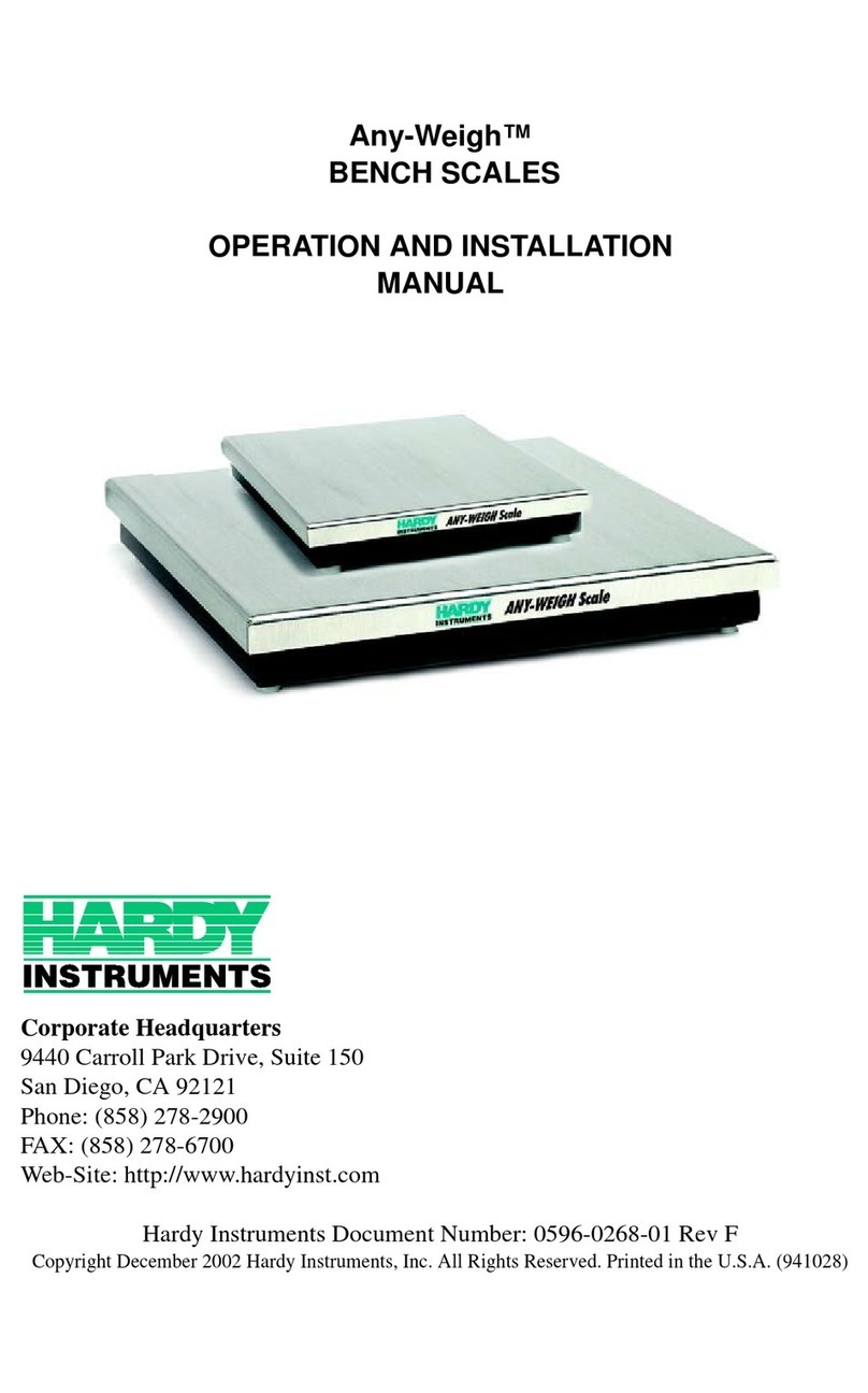
Hardy Instruments Any-Weigh Specification sheet

Any-Weigh™
FLOOR SCALES
OPERATION AND INSTALLATION
MANUAL
9440 Carroll Park Drive, Suite 150
San Diego, CA 92121
San Diego, CA 92123-1825
Phone: (858) 278-2900
FAX: (858) 278-6700
Web-Site: http://www.hardyinst.com
Hardy Instruments Document Number: 0596-0280-01 Rev D
Copyright October 2003 Hardy Instruments, Inc. All Rights Reserved. Printed in the U.S.A. (941028)

Local Field Service
Hardy has over 200 field technicians in the U.S., and more positioned
throughout the world to assist you in your support needs. We also have fac-
tory engineers who will travel to your facility anywhere in the world to help you
solve challenging applications. We're ready to support you with:
•Installation and start-up
•Routine maintenance and certification
•Plant audits and performance measurement
•Emergency troubleshooting and repair
To request Emergency Service and Troubleshooting, Start-up, Installation,
Calibration, Verification or to discuss a Maintenance Agreement please call
800-821-5831 Ext. 1757 or Emergency Service after hours (Standard Hours
6:00 AM to 6:00 PM Pacific Standard Time) and weekends Ext. 1111.

Outside the U.S
Hardy Instruments has built a network of support throughout the globe. For
specific field service options available in your area please contact your local
sales agent or our U.S. factory at +1 858-292-2710, Ext. 1757.
CAUTION:
UNPACK WITH CARE
WHEN UNPACKING, DO NOT DISCARD THE PACKING CASE OR ANY
PACKING MATERIAL, UNTIL THE CONTENTS OF THE PACKING CASE
ARE INSPECTED AND CAREFULLY COMPARED WITH THE SHIPPING
DOCUMENTS.
IF ANYTHING IS UNSATISFACTORY, PLEASE NOTIFY HARDY INSTRU-
MENTS IMMEDIATELY BY CALLING, FAXING OR E-MAILING TO:
Hardy Service Center
HARDY INSTRUMENTS, INC.
9440 Carroll Park Drive, Suite 150
San Diego, CA 92121
Phone: (800) 821-5831
(858) 278-2900
FAX:(858) 278-6700
E-mail: disupport@hardyinst.com
Web Address: www.hardyinst.com
TO RETURN DEFECTIVE OR DAMAGED PRODUCT(S) CALL HARDY
TECHNICAL SUPPORT FOR A HARDY SERVICE TICKET NUMBER
(HST#). YOUR COMPANY NAME, ADDRESS, TELEPHONE NUMBER,
SERIAL NUMBER OF THE UNIT AND A BRIEF DESCRIPTION OF THE
PROBLEM SHOULD BE READY WHEN CALLING. FOR ALL NON-WAR-
RANTY REPAIRS A PURCHASE ORDER OR CREDIT CARD IS ALSO
REQUIRED.
IN CASE OF DAMAGE DUE TO SHIPPING, NOTIFY THE DELIVERING
CARRIER IMMEDIATELY FOR AN INSPECTION.


Table of Contents
i
Table of Contents
Table of Contents - - - - - - - - - - - - - - - - - - - - - - - - - -i
Table of Illustrations - - - - - - - - - - - - - - - - - - - - - - - -I
SPECIFICATIONS - - - - - - - - - - - - - - - - - - - - - - - - - -1
Platform Material - - - - - - - - - - - - - - - - - - - - - - - - -1
Platform Height- - - - - - - - - - - - - - - - - - - - - - - - - -1
Rated Output - - - - - - - - - - - - - - - - - - - - - - - - - - -1
Excitation- - - - - - - - - - - - - - - - - - - - - - - - - - - - -1
Total Error - - - - - - - - - - - - - - - - - - - - - - - - - - - -1
Maximum Overload- - - - - - - - - - - - - - - - - - - - - - - -1
Endloading - - - - - - - - - - - - - - - - - - - - - - - - - - - -1
Temperature Range - - - - - - - - - - - - - - - - - - - - - - -1
Temperature Effect - - - - - - - - - - - - - - - - - - - - - - - -1
Cable Length - - - - - - - - - - - - - - - - - - - - - - - - - - -1
Materials of Construction - - - - - - - - - - - - - - - - - - - - -1
Steel - - - - - - - - - - - - - - - - - - - - - - - - - - - - -1
Paint - - - - - - - - - - - - - - - - - - - - - - - - - - - - -2
Foot Elastomer - - - - - - - - - - - - - - - - - - - - - - - -2
Grade Level - - - - - - - - - - - - - - - - - - - - - - - - - - -2
Accessories - - - - - - - - - - - - - - - - - - - - - - - - - - -2
Anchor Bolt Holds - - - - - - - - - - - - - - - - - - - - - -2
Approvals - - - - - - - - - - - - - - - - - - - - - - - - - - - -2
NEMA Rating- - - - - - - - - - - - - - - - - - - - - - - - - - -2
Test Criteria - - - - - - - - - - - - - - - - - - - - - - - - -2
GENERAL INFORMATION - - - - - - - - - - - - - - - - - - - - - -2
UNPACKING - - - - - - - - - - - - - - - - - - - - - - - - - - - - -3
COMPONENT DESCRIPTIONS - - - - - - - - - - - - - - - - - - -4
SITE PREPARATION- - - - - - - - - - - - - - - - - - - - - - - - -5
Precautions - - - - - - - - - - - - - - - - - - - - - - - - - - -6
FLOOR SCALE INSTALLATION - - - - - - - - - - - - - - - - - - -7
CALIBRATION - - - - - - - - - - - - - - - - - - - - - - - - - - - -10
Pre-Calibration Procedures - - - - - - - - - - - - - - - - - - - -10
C2® Second Generation Calibration - - - - - - - - - - - - - - -11
Test Weight Calibration (Hard Cal) - - - - - - - - - - - - - - - -11

Any-Weigh™ Series Floor Scales
ii
Requirements: - - - - - - - - - - - - - - - - - - - - - - - -11
Material Substitution: - - - - - - - - - - - - - - - - - - - - -12
SCALE VERIFICATION- - - - - - - - - - - - - - - - - - - - - - - -12
MODEL CODE BREAKDOWN - - - - - - - - - - - - - - - - - - - -13
Mild Steel Deck, Painted - - - - - - - - - - - - - - - - - - - - -13
Stainless Steel Deck (304 SS) - - - - - - - - - - - - - - - - - -14
REMOVING SUMMING BOX COVER- - - - - - - - - - - - - - - - -15
Installing the Leveling Feet - - - - - - - - - - - - - - - - - - - -18
INSTALLING A LOAD SENSOR - - - - - - - - - - - - - - - - - - -21
OPTIONAL PIT FRAMES- - - - - - - - - - - - - - - - - - - - - - -25
About Pit Frames - - - - - - - - - - - - - - - - - - - - - - - - -25
OPTIONAL ACCESS RAMPS- - - - - - - - - - - - - - - - - - - - -29
Access Ramp Installation - - - - - - - - - - - - - - - - - - - - -29
OPTIONAL BOLT-DOWN PLATES - - - - - - - - - - - - - - - - - -31
Bolt-Down Plates Installation - - - - - - - - - - - - - - - - - - -32
OPTIONAL BUMPER GUARDS- - - - - - - - - - - - - - - - - - - -33
TROUBLESHOOTING - - - - - - - - - - - - - - - - - - - - - - - -36
INSTRUMENTATION INTERFACE CABLE COLOR CODES - - - - -37

Table of Illustrations
I
Table of Illustrations
TABLE OF ILLUSTRATIONS- - - - - - - - - - - - - - - - - - - - -I
FIG. 1 INSTALLING THE CLOSED EYEBOLTS INTO THE TOP
PLATE - - - - - - - - - - - - - - - - - - - - - - - - - - -4
FIG. 2 SUMMING JUNCTION CARD - - - - - - - - - - - - - - - -5
FIG. 3 DIRECTION WHEN DRIVING HEAVY EQUIPMENT
ON AND OFF THE SCALE - - - - - - - - - - - - - - - -7
FIG. 4 MAXIMUM HEIGHT - - - - - - - - - - - - - - - - - - - - -7
FIG. 5 SPIRIT LEVEL- - - - - - - - - - - - - - - - - - - - - - - -8
FIG. 6 CHECKING PLATFORM LEVEL/SIDE TO SIDE - - - - - - -8
FIG. 7 CHECKING PLATFORM LEVEL/CORNER TO CORNER- - -9
FIG. 8 CHECKING PLATFORM LEVEL/DIAGONALLY - - - - - - -9
FIG. 9 ADJUSTING THE FEET FOR LEVEL - - - - - - - - - - - -10
FIG. 10 SCALE VERIFICATION/POSITION #3 - - - - - - - - - - - -12
FIG. 11 REMOVING THE SUMMING BOX COVER- - - - - - - - - -16
FIG. 12 REMOVING THE SUMMING BOX LID - - - - - - - - - - - -17
FIG. 13 REMOVING THE SUMMING BOX LID - - - - - - - - - - - -18
FIG. 14 INSERTING THE LEVELING FOOT INTO THE
LOAD SENSOR - - - - - - - - - - - - - - - - - - - - -19
FIG. 15 INSIDE VIEW - - - - - - - - - - - - - - - - - - - - - - - -20
FIG. 16 OUTSIDE VIEW - - - - - - - - - - - - - - - - - - - - - - -20
FIG. 17 ALL FOUR FEET INSTALLED - - - - - - - - - - - - - - - -21
FIG. 18 SUMMING CARD - - - - - - - - - - - - - - - - - - - - - -21
FIG. 19 CORD GRIP- - - - - - - - - - - - - - - - - - - - - - - - -23
FIG. 20 REMOVING LOAD SENSOR BOLTS AND FEET- - - - - - -24
FIG. 21 FOUNDATION FOR THE PIT FRAME - - - - - - - - - - - -26
FIG. 22 PIT FRAME DIMENSIONS- - - - - - - - - - - - - - - - - -26
FIG. 23 DRAIN INSTALLATION DIMENSIONS - - - - - - - - - - - -28
FIG. 24 EXCAVATED PIT AND SUPPORT FOR THE PIT FRAME - -28
FIG. 25 RAMP WITH RETAINER PLATES - - - - - - - - - - - - - -30
FIG. 26 INSTALLING ANCHORS FOR RAMP - - - - - - - - - - - -30
FIG. 27 BOLT DOWN PLATES/INSTALLATION - - - - - - - - - - -32
FIG. 28 BUMPER GUARD/GAP REQUIREMENT- - - - - - - - - - -33
FIG. 29 BUMPER GUARD/INSTALLATION- - - - - - - - - - - - - -34

Any-Weigh™ Series Floor Scales
II

Any-Weigh™ Series Floor Scales
1
SPECIFICATIONS
Platform Material 0.25 inch
Platform Height 3.0 inches +.275”
Rated Output 2.0mV/V ±0.1%
Excitation • Recommended 5 Volts DC
•Maximum5VoltsDC
WARNING FOR SCALES FITTED WITH AN INTEGRATED
TECHNICIAN SUMMING CARD, DO NOT
EXCEED 5 VDC EXCITATION. DOING SO MAY
CAUSE PROPERTY DAMAGE. DO NOT USE
WITH THESE INSTRUMENTS: HI 2160, HI
1771 OR ANY INSTRUMENT WITH AN EXCI-
TATION VOLTAGE ABOVE 5 VDC.
Total Error 0.03% of FS Output
Maximum
Overload 150% of the Rated Scale Capacity
Endloading 100% of the Rated Scale Capacity
Temperature
Range • Safe -40º to +80º Degrees C (-40º to +176º
F)
• Compensated -10 to +40 Degrees C (+14º to
104º Degrees F)
Temperature
Effect • On Output - 0.0011% of load/Deg. C
• On Zero - 0.0011% of FSO/Deg C
Cable Length 20 feet (C2 Cable)
NOTE: To purchase C2 Cable contact our local Hardy Instru-
ments Representative or Hardy Instruments Service
Center.
Materials of
Construction
Steel • Mild Steel: Type A36 carbon plate steel (slip
resistance - tread or smooth surface)

Any-Weigh™ Series Floor Scales
2
• Stainless Steel: Type 304 plate steel (slip
resistance - tread or smooth surface)
Paint 100% Acrylic Emulsion (mild steelfloor scale models
only - Stainless Steel scales are not painted)
Foot
Elastomer • Natural Rubber (Standard)
Grade Level In operation, the scale must be firmly and adequately
supported at all four corners to accommodate the
maximum load in your application. The scale must be
installed to within 3º of level.
Accessories Ramps, Pit Frames, Bumper Guards, Lifting Eyebolts,
Bolt Down Plates
Anchor Bolt
Holds 1/2 inch bolts - 9/16” (.5625”) hole, 3.75 inches deep
5/8 inch bolts - 5/8” (.6250”) hole, 4.0 inches deep
Approvals • NTEP Class III Number: 04-087
NEMA Rating Summing Junction Box Enclosure - NEMA 4X Stain-
less Steel
Test Criteria Must exclude at least 65 GPM of wate from 1” inch
nozzle deliverd from a distance not less than 10 ft for
5 minutes.
GENERAL
INFORMATION The Hardy Instruments AnyWeigh™ Series Floor
Scales are designed for applications that require a low
profile weighing surface with high commercial accu-
racy and reliability. The Hardy Floor Scales can be
configured with a complete range of accessories. The
scales can also be configured to fit any floor scale
application.
The typical platform height is three (3) inches. Each
corner can be adjusted an additional .275” (7mm) to
compensate for a non-level floor or pit mounting sur-
face.
The Any-Weigh Floor Scales do not have bearings,
levels or moving parts that can be damaged or wear

Any-Weigh™ Series Floor Scales
3
out. The active elements of the floor scales are four
precision strain gauge load sensors, mounted on all
four corners of the scale platform. The unique Blind
Hole Load Introduction technology allows the foot to
move to compensate for uneven floors. This ensures
that the load forces are always applied to the load sen-
sor at precisely the same point regardless of where the
load is placed on the scale. This ensures you will get
accurate and repeatable weighments.
Each platform load sensor is initially certified for use
in a C2®Second Generation Calibration system.
UNPACKING The Any-Weigh Series Floor Scales are shipped fully
assembled and wired. Inspect the container for any
signs of damage that might occur during shipment.
Since almost all of the Floor Scales are shipped
F.O.B. factory, such damage is normally the responsi-
bility of the carrier and should be reported to them.
Step 1. Remove the banding straps and any ship-
ping restraints.
WARNING DO NOT USE HOOKS OR UNCLOSED EYE-
BOLTS OR ATTEMPT TO LIFT THE SCALE
MANUALLY. FAILURE TO USE THE PROPER
LIFTING TOOLS OR LIFTING METHODS CAN
CAUSE PERSONAL INJURY OR PROPERTY
DAMAGE.
Step 2. Screw 2 closed eyebolts into the threaded
holes on the top plate of the scale. (See
Fig. 1)
• Mild Steel - 1/2 - 13 x 1.5” (Hardy Model
Number HI EB2250-1)
Step 3. Attach a chain, cable or nylon strap to the
eyebolts.
Step 4. Use a forklift or crane with rated lifting
capacity that is equal to or greater than the
total weight of the platform scale to lift the
scale high enough to remove from the

Any-Weigh™ Series Floor Scales
4
crate bottom. See Tables 2 & 3 for ship-
ping weights.
Step 5. Be sure to use all safety precautions when
lifting the platform so that it does not fall
on equipment or personnel. It is highly
recommended that blocks be placed under
the platform before working near the plat-
form scale.
FIG. 1 INSTALLING THE CLOSED EYE-
BOLTS INTO THE TOP PLATE
COMPONENT
DESCRIPTIONS 1. Steel Plate Platform - The platform material is
either low carbon steel plate or 304 stainless steel
plate. The low carbon steel platform cover is
made from a single piece of 1/4" A36 carbon
steel floor plate (skid resistant) or smooth steel
plate. The steel platforms are primed and coated
with a tough weather resistant paint (See Paint
Specifications). The 304 stainless steel platform
is made from a single piece of 1/4" diamond tread
(Conforms to ASTM A793-85) floor plate (skid
resistant) or smooth stainless steel plate with a
bead blast finish.
2. Summing Junction Card Assembly - Accessed
by unfastening the face plate on the center side of
the platform. (See Fig.2) The summing junction
card routes the excitation voltage to each of the
four load sensors and sums the weight signal
Closed Eye Bolts
for Lifting the
Platform Scale

Any-Weigh™ Series Floor Scales
5
back from them. The C2®second generation
electronic calibration is included with your scale.
FIG. 2 SUMMING JUNCTION CARD
3. Load Sensors - The AnyWeigh series scales use
four (4) steel Advantage like load sensors with
hermetic seals. The output of each sensor is 2mV/
V with 5 Volts DC excitation. For more specifica-
tions see the electrical specification section of
this manual.
4. INTEGRATED TECHNICIAN™ (Option) -
(If IT summing card is installed) A built-in sys-
tem diagnostics utility, continuously monitors the
weighing system for possible malfunctions. This
capability also allows the operator to rapidly
troubleshoot a weighing system from the control-
ler or indicator.
5. Leveling Feet - Each AnyWeigh series scale
comes with four (4) 304 stainless steel adjustable
leveling feet. The leveling feet are adjustable to a
maximum of 7mm (.275"). The leveling feet are
attached to each of the load sensors.
SITE PREPARATION • All mounting surfaces for the floor scale
should be level to within 3º, corner to corner,
end to end. Keep in mind that the adjustable
leveling feet have a maximum adjustment of
7mm (.275”).

Any-Weigh™ Series Floor Scales
6
• Before welding anything on the floor scale,
contact Hardy Instruments Service Center
for instructions and precautions.
• Proper drainage must be provided to prevent
the load sensors from standing in water.
Precautions • Do not do any electric welding on or near the
platform scale.
• Do not drop items to be weighed on the
scale. Set them on the platform scale.
• Do not set items on the platform scale that
weigh more than the capacity of the scale.
• Do not store or operate the scale in environ-
ments out of the specified temperature range.
• Do not store other equipment on the scale
even temporarily when it is not used or in
storage.
• Do not allow debris to accumulate on,
around or under the scale.
• Do not set the scale in water or allow water
to accumulate around the scale. Always pro-
vide proper drainage.
• Do not let moisture get on or into any of the
electrical interconnections.
• Do not allow static or other electrical dis-
charges go through the scale.
• Do not leave the screws for the summing
junction box cover plate loose so that the
junction box is not sealed.
• Do not drop the scale when moving or
installing.
• When driving heavy equipment on and off
the scale for weighing purposes, make sure
that you drive onto and off of the platform in
the direction indicated in Figure 3. Also See
Access Ramp Installation Section.

Any-Weigh™ Series Floor Scales
7
FIG. 3 DIRECTION WHEN DRIVING HEAVY
EQUIPMENT ON AND OFF THE SCALE
FLOOR SCALE
INSTALLATION Step 1. Place the platform scale on the operating
location. Make sure that the platform
height is within 3 to 3.275" as measured
from the top of the cover plate to the top of
the floor surface. (See Fig. 4)
NOTE: With the scale in place, the clearance around the edge
of the platform and pit coping should be 1/4” to 3/8”.
FIG. 4 MAXIMUM HEIGHT
Load and unload
heavy equipment
in this direction only!
3.275” (83.1mm)

Any-Weigh™ Series Floor Scales
8
Step 2. Make sure that the platform mounting sur-
face is level to 1/8”.
Step 3. Use a spirit level to check if the platform is
level, side to side, corner to corner and
diagonally. (See Figs. 9, 10, 11, 12)
FIG. 5 SPIRIT LEVEL
FIG. 6 CHECKING PLATFORM LEVEL/SIDE
TO SIDE

Any-Weigh™ Series Floor Scales
9
FIG. 7 CHECKING PLATFORM LEVEL/COR-
NER TO CORNER
FIG. 8 CHECKING PLATFORM LEVEL/DIAG-
ONALLY
Step 4. Adjust each of the leveling feet in the
direction (either up or down), indicated by
the level readings. (See Fig. 9)
• To increase the height rotate the foot counter
clockwise.
• To decrease the height rotate the foot clock-
wise.

Any-Weigh™ Series Floor Scales
10
FIG. 9 ADJUSTING THE FEET FOR LEVEL
Step 5. Place a spirit level on the platform surface
again to check the adjustment for level.
Keep adjusting the legs until the platform
is level and all four leveling feet are firmly
on the floor surface.
Step 6. Check the distance from the top of the
platform to the floor surface at each cor-
ner. All the measurements should be
within 3º of each other and the platform
should be level.
Step 7. If the installation requires bolt down plates
to keep the floor scale in place go to the
Optional Bolt Down Plates Section for
instructions.
CALIBRATION
Pre-Calibration
Procedures Step 1. Open the Junction box cover. (See Fig. 11
for Instructions)
Step 2. Thread the C2® Certified cable through
the grommet on the side of the scale that
houses the junction box.
Foot

Any-Weigh™ Series Floor Scales
11
Step 3. Connect the C2 Certified Summing Card
Interface Cable to the weight instrument.
Color code wires as follows:
• + Excitation Red
•+Sense Blue
• + Signal Green
• - Signal White
•-Sense Brown
• - Excitation Black
•+C2 Grey
•-C2 Violet
Step 4. Use the weight instrument/indicator man-
ual for calibration instructions.
NOTE: To purchase C2®certified cable, contact your local
Hardy Representative or the Hardy Instruments Ser-
vice Center.
C2®Second
Generation
Calibration
Definition - C2®electronically calibrates a scale sys-
tem without the need for test weights. This feature is
in all Hardy weight or rate controllers, and in the
Allen-Bradley weight modules.
Step 1. Refer to the Hardy weight or rate control-
ler manuals or the Allen Bradley module
manual for instructions.
Test Weight
Calibration (Hard
Cal)
Requirements: • Test weight calibration requires the use of
certified class F test weights equal to a mini-
mum of 80% of the rated scale capacity.
• Three weights between 10% and 100% of
the scale capacity should be used to check
the mid range.
• Several low capacity weights equivalent to
one or two instrument divisions are required
to check the systems' sensitivity.

Any-Weigh™ Series Floor Scales
12
Material
Substitution: • When certified test weights are not available
you can use an accurately weighed material
instead.
• The material must be weighed on a second-
ary, calibrated scale and delivered to the site
of the primary floor scale for calibration.
• The secondary calibrated scale should be of
the same accuracy or greater and have a
capacity approximately equal to the primary
floor scale.
SCALE VERIFICATION Step 1. Get a test weight that is equal to 10% of
the full scale capacity.
Step 2. Place the test weight at Position #1 on the
platform. (See Fig. 10)
FIG. 10 SCALE VERIFICATION/POSITION #3
Step 3. Write down the weight for position #1.
Step 4. Place the weight at position #2.
Step 5. Write down the weight for position #2.
Step 6. Place the weight at position #3.
Step 7. Write down the weight for position #3.
Step 8. Place the weight at position #4.
Step 9. Write down the weight for position #4.
Step 10. Check all the readings. If all the readings
are within an acceptable tolerance, no re-
calibration is required.
Position #3
Position #4
Position #2
Position #1
Summing Box
Other manuals for Any-Weigh
1
Table of contents
Other Hardy Instruments Scale manuals
