Hardy KB125 User manual

Model – KB125
INSTALLATION AND
OPERATING INSTRUCTIONS
FOR
THE HARDY
OUTSIDE WOOD
BURNING HEATER
Model – KB125
HARDY MANUFACTURING
COMPANY, INC.
12345 ROAD 505
PHILADELPHIA, MS 39350
PHONE: (601) 656-5866
FAX: (601) 656-4559
www.hardyheater.com
Rev. 9/22/2014

THIS PAGE INTENTIONALLY LEFT BLANK

(MODEL KB125)
i
INTRODUCTION
Thank you for purchasing the EPA Phase 2 qualified model KB125. The KB125 is an
all stainless steel Hardy Outside Wood Fired Hydronic Heater. It represents the result
of many years of Hardy experience and the input of Hardy customers in the production
of a top quality heater. With the purchase of this Hardy Heater, you can now appreciate
the high degree of craftsmanship and reliability that have made “The Hardy” the leader
in the Outside Wood Fired Hydronic Heater field. This manual will provide you with a
good basic understanding of the installation and operation of this heater.
THIS MANUAL INCLUDES IMPORTANT SAFETY INFORMATION.
Your new heater should have the following:
(1) Owner’s manual complete with installation
and hook-up instructions
(2) Warranty & return warranty card
(3) 2 double wall sections of smoke stack & ring
(4) Ash shovel
(5) 2” flue brush with handle
(6) Fire poker
(7) Ash removal pan
Should your heater not have any of these items or if you have any questions regarding
the operation or maintenance of your heater, please consult you local Hardy dealer.
Again, thank you for purchasing a Hardy Hydronic Heater.
Sincerely,
Frank L. Moore
President
Hardy Manufacturing Co., Inc.

(MODEL KB125)
ii
Please fill in the following information
Hardy Model
Serial Number
Date of Purchase
Date of Installation
Dealer Purchased from
Dealer Address
Dealer Phone Number
HARDY MANUFACTURING COMPANY, INC.
12345 ROAD 505
PHILADELPHIA, MS 39350
PHONE: (601) 656-5866
www.hardyheater.com
Please keep this manual with all other important papers.
The information in this manual is necessary for the
installation, operation and proper use of this unit. If you
should ever have a problem or question please refer to
this manual or have it available when you call your Hardy
Dealer or Hardy Manufacturing Company, Inc.

(MODEL KB125)
iii
SAFETY PRECAUTIONS
WARNING
Do not operate this equipment for other than its intended purpose nor other
than in accordance with the instructions contained in this manual and all other
instructions accompanying the unit.
For units covered by this instruction book, it is important to observe safety precautions
to protect yourself from possible injury. Among the many considerations, you are
advised to:
Observe all safety stickers on the unit.
This unit must be wired by a qualified electrician in accordance with the National
Electrical Code.
Never use any type of petroleum based product, charcoal starter, lighter fluid, or
any other flammable accelerant to start your unit.
Fuel: Clean seasoned oak hardwood. Clean wood means wood that has no paint,
stains, or other types of coatings, and wood that has not been treated with
preservatives, including but not limited to, copper chromium arsenate, creosote, or
pentachlorophenol.
Never leave the door open, always latch the door securely.
Always use proper care when installing, operating and maintaining the unit.
Do not modify the unit.
Do not substitute repairs which can be provided by your dealer, distributor, or Hardy
Manufacturing Co. Inc.
Failure to heed this warning, any additional warnings on the unit, or instructions
contained in this manual may result in an accident causing personal injury and/or loss
of warranty.

(MODEL KB125)
iv
THIS PAGE INTENTIONALLY LEFT BLANK

(MODEL KB125)
v
OUTDOOR WOOD HEATER BEST BURN PRACTICES
1.1. Read and follow all operating instructions supplied by the manufacturer.
2. FUEL USED: Only those listed fuels recommended by the manufacturer of your unit.
Never use the following: trash, plastics, gasoline, rubber, naphtha, household
garbage, material treated with petroleum products (particle board, railroad ties and
pressure treated wood), leaves, paper products, and cardboard.
3. LOADING FUEL: For a more efficient burn, pay careful attention to loading times and
amounts. Follow the manufacturer’s written instructions for recommended loading
times and amounts.
4. STARTERS: Do not use lighter fluids, gasoline, or chemicals.
5. LOCATION: It is recommended that the unit be located with due consideration to the
prevailing wind direction.
6. Always remember to comply with all applicable state and local codes.
Outdoor Furnace Manufacturers Caucus
• Furnace should be located no less than 100 feet from any residence not served by
the furnace.
• If located within 100 feet to 300 feet to any residence not served by the furnace, it
is recommended that the stack be at least 2 feet higher than the peak of that
residence.
Chimney Height Installation Scenario
Residence
served by furnace
Residence not
served by furnace
Chimney height
should be 2 feet above roof line.
2 feet
Minimum of 100 feet

(MODEL KB125)
vi
THE HARDY OUTSIDE WOOD FIRED HYDRONIC HEATER
How does an outside heater heat my home?
The Hardy outside wood fired hydronic heater is designed to save the most energy and
provide the most comfortable heating available. It heats your home by heating a
stainless steel tank filled with water, which surrounds the firebox of the outside heater.
The heater is a non pressurized boiler with an atmospheric vent. This hot water is then
circulated through underground hot water pipes to a water coil inside your existing
central duct system. The Hardy Heater can be connected to any existing hydronic
heating system that operates at 170 degrees Fahrenheit or less.
How does THE HARDY heat water for household use?
A plate heat exchanger (optional) is installed in the hot water circulator line. When you
open a hot water faucet inside your home, the cold water passes through the other
side of the heat exchanger and the water going to your water heater is preheated. The
only additional energy required is maintaining the water temperature. The plate heat
exchangers can be used for pools, dairies and other domestic hot water needs.
How do the Thermostat Controls work?
The only visible addition to the heating system inside your home is the thermostat
which is located next to your existing thermostat. The two thermostats are installed so
that if the outside wood burning heater is not in operation, your existing unit can be
used to maintain your household temperature. The wall thermostat which regulates the
heat from the outside heater turns the blower on inside your central unit to force air
across the hot coil. This forces hot air into your central duct system. The outside
heater has a Process Control Module which senses the water temperature of the unit.
This module cycles the heater on and off in order to maintain a preset water
temperature.
Where should the Hardy Heater be located?
The outside unit should be located at least 10 feet from your home, other structures or
any other combustible materials so that all fire danger is removed. Additional refer to
the Best Burn Practices section in this manual. Locate the outside wood burning
heater where it will be convenient for refueling. All water and power lines are installed
underground between the house and the outside wood heater.

(MODEL KB125)
vii
Additional Installation and Operational Considerations
Installation
Person(s) operating a Hardy hydronic heater must comply with all applicable
laws or other requirements, such as state laws or regulations and local
ordinances. Person(s) is/are also responsible for operation in a manner that
does not create a public or private nuisance condition. The distance and stack
height Hardy Mfg. recommends and the requirements in any applicable laws or
other requirements may not always be adequate to prevent nuisance
conditions due to terrain or other factors.
EPA’s Burnwise Program
http://www.epa.gov/burnwise
How to Use a Moisture Meter Video
http://www.youtube.com/watch?v=jM2WGgRcnm0
EPA offers tips on how to properly use a moisture meter to test firewood
before using in a wood-burning stove or fireplace. Wet wood can create
excessive smoke which is wasted fuel.
Split, Stack, Cover and Store Video
http://www.youtube.com/watch?v=yo1--Zrh11s
EPA offers four simple steps to properly dry firewood before using in a
wood-burning stove or fireplace. Wet wood can create excessive smoke
which is wasted fuel. Burning dry, seasoned firewood with a moisture
content of 20% or less can save money and help reduce harmful air
pollution.
Wet Wood is a Waste brochure
http://www.epa.gov/burnwise/pdfs/wetwoodwastebrochure.pdf
This tri-fold brochure provides colorful illustrations of the four easy steps
to dry firewood.

(MODEL KB125)
viii
TABLE OF CONTENTS
SECTION I: General Information
1-1 Specifications...............................................................1
1-2 Heater Component Parts ..........................................2-4
SECTION II: Installation of Heater
2-1 Location of Heater........................................................5
2-2 Chimney Connection....................................................6
2-3 Location of Plumbing & Electrical Lines .......................6
2-4 Connection of Power to Heater ....................................7
2-5 Wiring Diagram .........................................................7-8
2-6 Plumbing Connections .................................................9
2-7 Installation of Smoke Stacks and Condenser Stack 10
2-8 Filling the Heater with Water……………………………11
2-9 Priming the Pump ......................................................12
SECTION III: Connection to Central Heating/AC System
3-1 Connection to Central Unit
with Existing Blower Relay ...................................13-14
3-2 Location of Heating Coil .......................................15-16
SECTION IV: Connection to Hydronic Heating Systems (Baseboard)
4-1 Connection to Hydronic System .................................17
SECTION V: Plumbing Options for Domestic Water
5-1 Plate Heat Exchanger for Domestic Hot Water .........18
SECTION VI: Heater Operation
6-1 Firing the KB125 ........................................................19
6-2 Loading the KB125 ....................................................20

(MODEL KB125)
ix
TABLE OF CONTENTS continued
SECTION VII: Service Information
7-1 Water Temperature.................................................... 21
7-2 Fuel Usage ................................................................ 21
7-3 Moisture in the Firebox .............................................. 21
7-4 Improper Burning ....................................................... 21
7-5 Ash Removal ............................................................. 21
7-6 Water Circulation System .......................................... 22
7-7 Combustion Air Blower Assembly…………………… . 22
7-8 Low Water Sensor ..................................................... 22
7-9 Temperature Logic Controller .................................... 22
7-10 Low Water Lockout Relay ........................................ 22
7-11 Timer........................................................................ 22
7-12Time Delay Relay...................................................... 22
SECTION VIII: Heater Maintenance
8-1 Weekly Maintenance.................................................. 23
8-2 Monthly Maintenance................................................. 24
8-3 Extended Period Shut Down and Start Up................ 25

HARDY MANUFACTURING CO., INC (MODEL KB125) PAGE 1
SECTION I
GENERAL INFORMATION
1 –1 Specifications
Type of fuel –Clean seasoned oak hardwood
Clean Wood means wood that has no paint, stains, or other types of coatings, and
wood that has not been treated with preservatives, including but not limited to, copper
chromium arsenate, creosote, or pentachlorophenol.
Wood Dimension & Condition -
22” to 24” in Length, 15% - 30% Moisture, Cured between 6 to 9 months.
Any round wood over 7” in diameter must be split at least once.
Wood Load Capacity -
10 to 15 pounds / cubic ft.
Firebox is approximately 7 Cubic Feet
Wood weight is approximately 80 to 100 pounds.
For Outdoor Use Only
Electrical Rating 115 VAC/ 60 HZ / 1PH
MFS-20 AMP, MCA-20 AMP
Clearance to Combustibles
Top, Rear, Sides 18”
Chimney Connector 18”
Front 48”
Flooring Non Combustible
Water Capacity
KB125 –Holds Approximately 80 Gallons of Water
Heater Outside Dimensions
Model Width Depth Height Weight
KB125 - 120,000 BTU 32 1/2” 61” 69” 1086 lbs.

HARDY MANUFACTURING CO., INC (MODEL KB125) PAGE 2
1-2 Heater Component Parts Model KB125
Standard Components
Legend Part No. Description
1 9125.50 Continuity Probe
2 2004.00 Ground Fault Interrupter Receptacle
3 2004.30 Terminal Block Assy.
4 506.30 SS Anti-Stratification Circulator
(Can Not Be Used To Supply System Loop)
5 2002.69 Combustion Blower
6 2065.10 Temperature Logic Controller (Not Visible)
7 2000.65 Time Delay Relay
8 2001.05 Damper Solenoid
9 2000.53 (2) Low Water Lockout Relay
10 2000.55 (2) Socket For Low Water Lockout Relay
11 607.42 3/4” Boiler Fill/Drain (Not Visible)
12 607.45 (3) 1” Brass Ball Valve
6
5
3
2
1
7
12
8
12
11
10
9
12
4
System Loop
Return
System Loop
Supply
HARDY MANUFACTURING CO., INC (MODEL KB125) PAGE 3
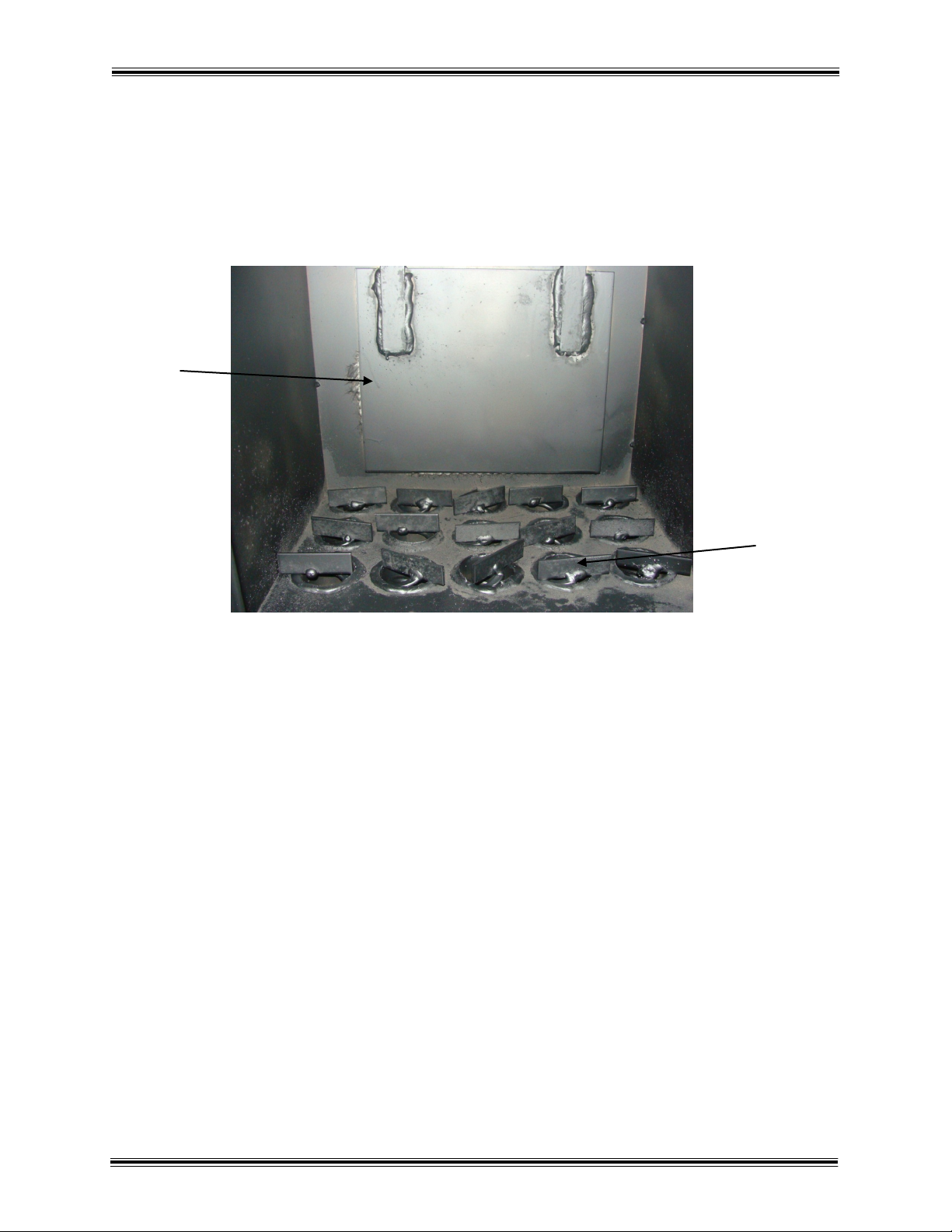
1-2 Heater Component Parts Model KB125
Standard Components (continued)
Legend Part No. Description
1 2065.50 (15) Turbulators
2 7165.99 Bypass Damper
2
1

HARDY MANUFACTURING CO., INC (MODEL KB125) PAGE 4
1-2 Heater Component Parts Model KB125
Standard Components (continued)
Legend Part No. Description
1 3105.17 (4) Refractory Grates
2 2165.31 (2) Front & Back Fire Bricks
1
2

HARDY MANUFACTURING CO., INC (MODEL KB125) PAGE 5
SECTION II
INSTALLATION OF HEATER
2-1 Location of Heater
The Hardy Heater is designed to operate outside the structure to be heated. The unit
must be located a minimum of 10 feet from any structure.
The heating unit should be installed on a concrete pad with a recommended minimum
dimension of 34”W x 61”L x 4”D. On the plumbing end of the heater you will need to
bring up through the pad a 4” water tight chase pipe to route your water lines and
electrical lines from the structure to be heated to the furnace.
Reference the illustration below for pad layout and ideal placement of 4” pipe.
Concrete Pad
Top View
4" pipe should be located
within shaded area.
4.00
9.00
6.00
5.00
34.00
61.00

HARDY MANUFACTURING CO., INC (MODEL KB125) PAGE 6
2-3 Location of Plumbing & Electrical Lines
To locate the connection points for plumbing and electrical lines you will need to open
the back hull door. The plumbing and electrical lines for your unit must be installed
underground in a water tight pipe or other suitable insulation means. The water lines
must be buried below the frost line to prevent freezing. Verify the correct depth
according to local building codes prior to installation.
The installation will require a trench wide enough to accommodate a 4” water tight pipe
or other insulation means. All plumbing and electrical lines should be installed inside
the 4” water tight pipe or other insulation means for a standard installation.
This pipe will run from the rear of the unit to the location to be heated. Contained inside
the 4” watertight pipe is 2 water lines and electrical supply wire. The listing below
describes each line and related function.
1. One 1” water supply line to heating system
2. One 1” water return line from heating system
(Note: The supply and return lines must be 1” pipe .)
3. One #12/2 w/gnd NM type UF underground wire
2-2 Chimney Connection
Do not connect this unit to a chimney flue servicing another appliance

HARDY MANUFACTURING CO., INC (MODEL KB125) PAGE 7
2-4 Connection of Power to Heater
This unit must be wired by a qualified electrician
in accordance with the National Electrical Code.
Verify that all electrical power is turned off. Install a 20 amp circuit with #12/2 W/Gnd
NM Type UF wire from the power source through the 4” watertight pipe or other
means to the heater. This wire will connect to the “LINE” Terminals on the GFCI
Receptacle located on the rear of the Heater. The breaker installed at the power
source should be a 20 amp GFCI.
2-5 Wiring Diagram
This equipment must be installed in accordance
with the National Electrical Code.
( See wiring diagram next page )

HARDY MANUFACTURING CO., INC (MODEL KB125) PAGE 8
2-5 Wiring Diagram (continued)

HARDY MANUFACTURING CO., INC (MODEL KB125) PAGE 9
Existing
Boiler
Heat
Zone
Heat
Zone
Existing
Pump
Close this valve
Hardy
P/N 300.01
40 Plate Heat
Exchanger
with 1" fittings
Heater with hull and stacks
removed to show connections
2-6 Plumbing Connections
Connection to Heating System
1. The pipe that will supply the heating system is connected to the first tee connection
above the pump.
2. The pipe that will carry the return water from the heating system is connected to the
second tee fitting after the pump.
Table of contents
Other Hardy Heater manuals


