Hardy C3 User manual

Model – C3 & C5
INSTALLATION AND
OPERATING INSTRUCTIONS
FOR
THE HARDY
OUTSIDE COAL
BURNING HEATER
HARDY MANUFACTURING
COMPANY, INC.
12345 ROAD 505
PHILADELPHIA, MS 39350
PHONE: (601) 656-5866
FAX: (601) 656-4559
www.hardyheater.com
Model – C3 & C5
Rev. 3/25/2015

THIS PAGE INTENTIONALLY LEFT BLANK

(MODEL C3 & C5)
i
INTRODUCTION
Thank you for purchasing the original all stainless steel Hardy Outside Coal Burning
Heater. It represents the result of many years of Hardy experience and the input of
Hardy customers in the production of a top quality heater. With the purchase of this
Hardy Heater, you can now appreciate the high degree of craftsmanship and reliability
that have made The Hardy the leader in the Outside Coal Burning Heater field. This
manual will provide you with a good basic understanding of the installation and
operation of this heater.
THIS MANUAL INCLUDES IMPORTANT SAFETY INFORMATION.
Your new heater should have the following:
(1) Owner’s manual complete with Installation
and Hook-Up Instructions
(2) Warranty & Return Warranty Card
(3) A tube of silicone (located in the firebox for shipping)
(4) Smoke stack and condenser tank stack both
with trim (located in the firebox for shipping)
(5) C3 has two I-beams and Shaker grates (located in the firebox)
C5 has two I-beams and Shaker grates (located in the firebox)
(6) box of Fire Brick and support pieces
(7) Shovel (located in the firebox for shipping)
(8) Stainless steel panel and insulation that will be
located between the firebox door & ash door
after installation of the heater
(9) Stainless steel flame baffle (15” x 10”). Only for
use on Hardy model C5
Should your heater not have any of these items or if you have any questions regarding
the operation or maintenance of your heater, please consult you local Hardy dealer.
Again, thank you for purchasing a Hardy Heater.
Sincerely,
Frank L. Moore
President
Hardy Manufacturing Company, Inc.

(MODEL C3 & C5)
ii
Please fill in the following information
Hardy Model
Serial Number
Date of Purchase
Date of Installation
Dealer Purchased from
Dealer Address
Dealer Phone Number
HARDY MANUFACTURING COMPANY, INC.
12345 ROAD 505
PHILADELPHIA, MS 39350
PHONE: (601) 656-5866
www.hardyheater.com
(MODEL C3 & C5)
iii
SAFETY PRECAUTIONS
WARNING
Do not operate this equipment for other than its intended purpose nor other
than in accordance with the instructions contained in this manual and all other
instructions accompanying the unit.
For units covered by this instruction book, it is important to observe safety precautions
to protect yourself from possible injury. Among the many considerations, you are
advised to:
Observe all safety stickers on the unit.
This unit must be wired by a qualified electrician in accordance with the National
Electrical Code.
Never use any type of petroleum product, petroleum based product, charcoal
starter, lighter fluid, or any other flammable accelerant to start your unit.
Always open the ash door (bottom) before you open the firebox door (top).
Never leave the doors open, always latch the doors securely.
Always use proper care when installing, operating and maintaining the unit.
Do not modify the unit.
Do not substitute repairs which can be provided by your dealer, distributor, or
Manufacturing Company.
Failure to heed this warning or any additional warnings on the unit may result in an
accident causing personal injury.
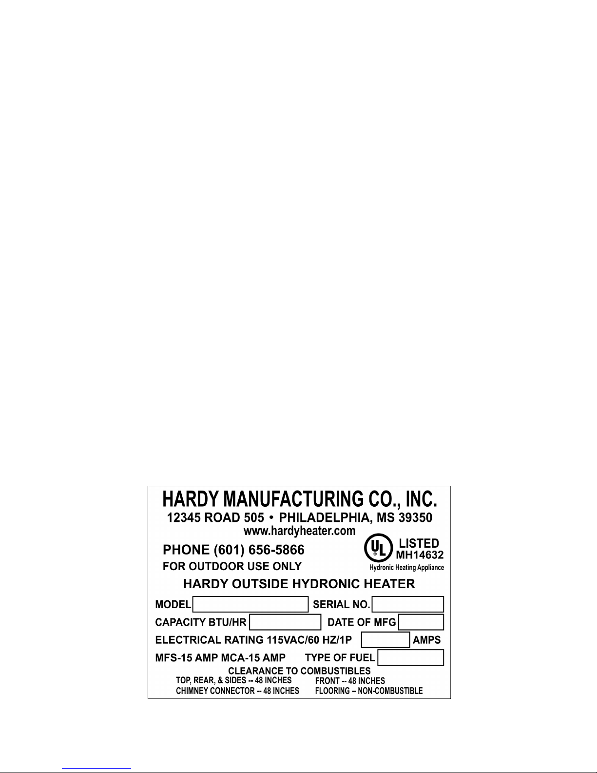
Safety Labels and Rating Labels
Read all safety labels on this unit
5” X 3.5”
C3-1-07
120,000
2.69
COAL

(MODEL C3 & C5)
iv
Safety Labels
Read all safety labels on this unit
Name Plate Supplement
5” X 10” (not shown actual size)

(MODEL C3 & C5)
v
Safety Labels
Read all safety labels on this unit
Heater Wiring Diagram
3” X 8”
R
WATER VALVE
LIQUID LEVEL
SWITCH
M
PUMP MOTOR
RELAY
R3
M
DAMPER BLOWER
MOTOR
DAMPER
AQUASTAT
M
PUMP MOTOR
RELAY
R3
OPTIONAL
SECOND
HEATING
ZONE
GROUND FAULT
CIRCUIT
INTERRUPTER
L 1
L 2
DAMPER SOLENOID
R
LLS
46
R 3
4 6
R 3
T1 BM
PM
PM
W V
SOL
GFCI L 2
L 1
LEGEND
GFCI GROUND FAULT CIRCUIT INTERRUPTER
LLS LIQUID LEVEL SWITCH
WV WATER SOLENOID VALVE
(OPTIONAL ON H3 & H5)
R3 CIRCULATOR PUMP RELAY
PM WATER CIRCULATOR PUMP
T1 DAMPER AQUASTAT
BM DAMPER BLOWER MOTOR
SOL DAMPER SOLENOID
R LOW WATER LIGHT
HEATER WIRING DIAGRAMS
CONNECTION DIAGRAM
SCHEM ATIC DIAGRAM
(MODEL C3 & C5)
vi
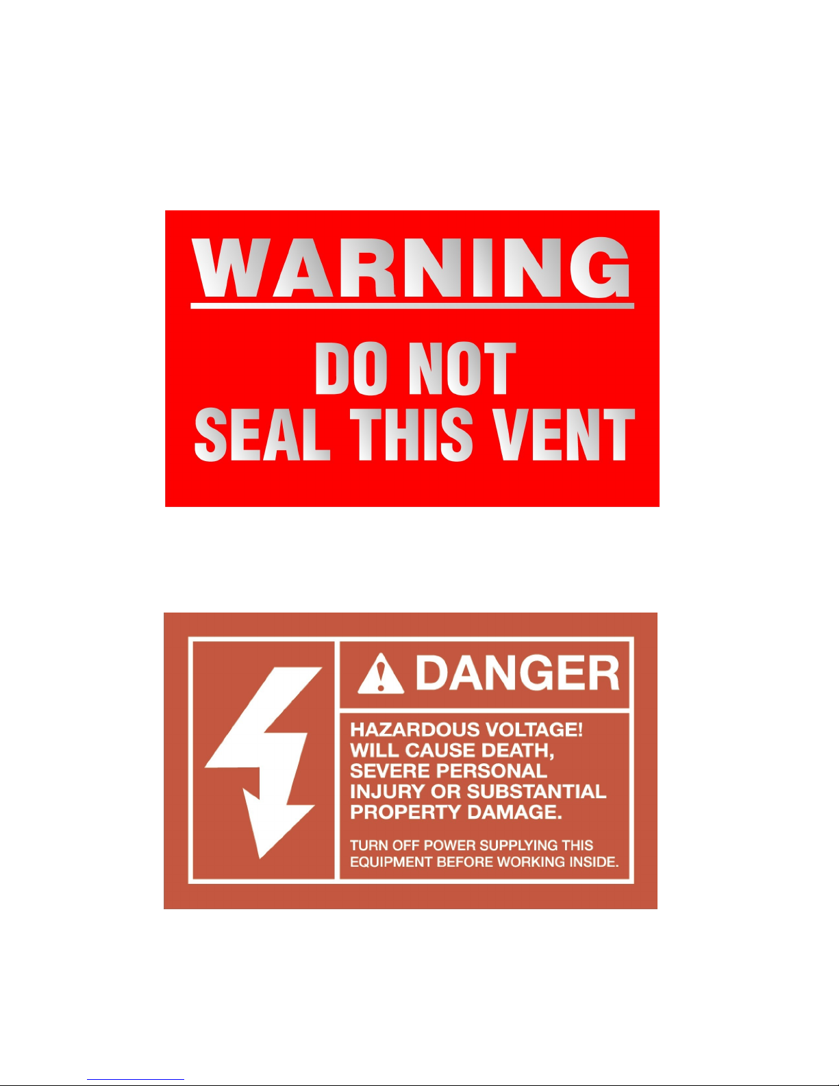
Safety Labels
Read all safety labels on this unit
Warning label for Condenser Vent
5” X 3”
Back Door label
5” X 3”

(MODEL C3 & C5)
vii
Safety Labels
Read all safety labels on this unit
Warning label on front between doors
4” X 2 3/4”
Field wiring label
2 3/4” X 1”
Hot water label
2 3/4” X 1”

(MODEL C3 & C5)
viii
THIS PAGE INTENTIONALLY LEFT BLANK
(MODEL C3 & C5)
ix
OUTDOOR FURNACE BEST BURN PRACTICES
1.1. Read and follow all operating instructions supplied by the manufacturer.
2. FUEL USED: Only those listed fuels recommended by the manufacturer of your unit.
Never use the following: trash, plastics, gasoline, rubber, naphtha, household
garbage, material treated with petroleum products (particle board, railroad ties and
pressure treated wood), leaves, paper products, wood, and cardboard.
3. LOADING FUEL: For a more efficient burn, pay careful attention to loading times and
amounts. Follow the manufacturer’s written instructions for recommended loading
times and amounts.
4. STARTERS: Do not use lighter fluids, gasoline, or chemicals.
5. LOCATION: It is recommended that the unit be located with due consideration to the
prevailing wind direction.
6. Always remember to comply with all applicable state and local codes.
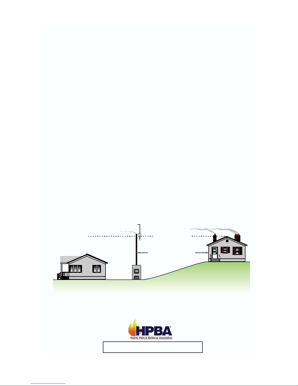
Outdoor Furnace Manufacturers Caucus
• Furnace should be located no less than 100 feet from any residence not served by
the furnace.
• If located within 100 feet to 300 feet to any residence not served by the furnace, it
is recommended that the stack be at least 2 feet higher than the peak of that
residence.
Chimney Height Installation Scenario
Residence
served by furnace
Residence not
served by furnace
Chimney height
should be 2 feet above roof line.
2 feet
Minimum of 100 feet

(MODEL C3 & C5)
x
THE HARDY OUTSIDE COAL BURNING HEATER
How does an outside heater heat my home?
The Hardy Outside Coal Burning Heater is designed to save the most energy and
provide the most comfortable heating available. It heats your home by heating a
stainless steel tank filled with water, which surrounds the firebox of the outside heater.
The heater is basically a non pressurized boiler with an atmospheric vent. This hot
water is then circulated through underground hot water pipes to a water coil inside your
existing central duct system. The Hardy heater can be connected to any existing
hydronic heating system that operates at 180 degrees or less.
How does THE HARDY heat water for household use?
A cold water supply line goes to the outside heater. This water line also keeps the
water tank of the heater full. The heater only takes on water as it evaporates. The cold
water line is connected to a heat exchanger which lies inside the water reservoir of the
outside heater. The pressure on the supply line forces water through the heat
exchanger when you open a hot water faucet inside your home. As this water passes
through the heat exchanger it picks up the heat from the hot water that surrounds it
and then goes to the cold side of your water heater. This means your water heater will
take on hot water. This water is not contaminated with the water that passes through
your heater and coil to heat your house.
How do the Thermostat Controls work?
The only visible addition to the heating system inside your home is the thermostat
which is located near the existing thermostat. The two thermostats are installed so that
if the outside heater is not in operation, your existing unit will automatically take over to
maintain the household temperature. The wall thermostat which regulates the heat
from the outside heater performs two functions; when it senses the need for heat, it
turns the water pump on to circulate the hot water through the coil and also turns the
blower on inside your central unit to force air across the hot coil. This forces hot air
into your central duct system. The outside heater has a hot water thermostat which
senses the water temperature of the unit. If the water is not as hot as the thermostat
setting then the combustion air intake is automatically opened and remains open until
such temperature is attained.
Where should an Outside Coal Burning Heater be located?
The outside unit should be located at least 10 feet from your home so that all fire
danger is removed from your home. The unit may be installed as much as 100 feet
away and still heat your house and hot water. If the unit is located more than 100 feet
away, you may experience some heat loss on the water going to your hot water heater.
Locate the outside coal heater where it will be convenient for refueling and fuel
storage. All water and power lines are installed underground between the house and
the outside heater.

(MODEL C3 & C5)
xi
TABLE OF CONTENTS
SECTION I: General Information
1-1 Specifications............................................................1-2
1-2 Heater Component Parts Model C3 .............................3
1-3 Heater Component Parts Model C5 .............................4
SECTION II: Installation of Heater
2-1 Location of Heater.....................................................5-6
2-2 Hull Removal................................................................7
2-3 Set-Up of Fire brick .................................................8-10
2-4 Location of Plumbing & Electrical Lines .....................11
2-5 Connection of Power to Heater ..................................12
2-6 Wiring Diagram ..........................................................13
SECTION III: Plumbing Instructions
3-1 Plumbing Instructions for Forced Air..........................14
3-2 Location of Heating Coil .......................................15-16
3-3 Connecting to Existing Hydronic Systems ............17-18
3-4 Plumbing for Domestic water C3 & C5 ......................19
3-5 Replacing Hull ...........................................................20
3-6 Filling the Heater with Water .....................................21
SECTION IV: Connection to Central Heating/AC System
4-1 Connection to Central Unit
with Existing Blower Relay ...................................22-23
4-2 Typical Wiring Diagram ............................................24
SECTION V: Heater Operation
5-1 Firing the Heater ........................................................25
5-2 Water Temperature ...................................................25
5-3 Moisture in the Firebox ..............................................25
5-4 Fuel Usage ................................................................26
5-5 Improper Burning.......................................................26
5-6 Ash Removal .............................................................26

(MODEL C3 & C5)
xii
SECTION VI: Service Information
6-1 Electric Make-Up Water System................................27
6-2 Water Circulation System ..........................................27
6-3 Temperature Control System ....................................28
SECTION VII: Heater Maintenance
7-1 Preventative Maintenance .........................................29
7-2 Preseason Maintenance.......................................30-31
7-3 In Season Maintenance........................................31-32
7-4 Post Season Maintenance.........................................32
SECTION VIII: Appendix
8-1 General Trouble Shooting Guide ..........................33-40
8-2 Circulator Maintenance Instructions......................41-42
8-3 Damper Solenoid Replacement Instructions ..............43
8-4 Low Water Switch Replacement Instructions ........44-45
8-5 Draft Blower Replacement Instructions .................46-47
8-6 Aquastat Replacement Instructions.......................48-50
SECTION IX:Warranty
9-1 Warranty ....................................................................51

HARDY MANUFACTURING CO., INC (MODEL C3 & C5) PAGE 1
SECTION I
GENERAL INFORMATION
1-1 Specifications
Type of fuel –Coal, (Use of wood in the appliance, except for coal ignition
purposes, is prohibited by law. The use of any other
fuel will void the warranty)
For outdoor use only
Electrical Rating 115 VAC/ 60 HZ / 1PH
MFS-15 AMP, MCA-15 AMP
Clearance to Combustibles
Top, Rear, Sides 48”
Chimney Connector 48”
Front 48”
Flooring Non Combustible
Water Capacity
C3 –Holds Approximately 100 Gallons of Water
C5 –Holds Approximately 130 Gallons of Water
Heater Dimensions
Description Width Depth Height Weight
C3 –120,000 BTU 30” 52 ½” 59 ½” 820 lbs.
C5 –180,000 BTU 40” 52 ½” 59 ½“ 945 lbs.
Firebox sizes
Description Width Depth Height
C3 –120,000 BTU 24” 32” 36” + 8” for Grates
C5 –180,000 BTU 34” 32” 36” + 8” for Grates

HARDY MANUFACTURING CO., INC (MODEL C3 & C5) PAGE 2
On the front of your heater there is a nameplate. Along with other information you will
find the model number of your heater. This model number tells you what your heater
rating is and what electrical and plumbing options your heater has, use the following
list to determine this. The first section determines the rating of your heater. The second
section determines electrical options. The last section determines the plumbing
options. For example heater model number C3-1-07. The C3 designates that you have
a 120,000 BTU heater. The 1in the second section designates that you have a
standard pump. The 7in the last section designates that you have extra ports on your
heater.
Heater Rating
C3 –120,000 BTU
C5 –180,000 BTU
C3-1-07
120,000
2.69
COAL
1-1 Specifications
Electrical Options
0 –Without a Pump
1 –Standard Pump
2 –2nd Pump & Relay
3 –3rd Pump & Relay
8 - Optional External Plate & Circulator
9 - Optional Automatic Water Fill
Plumbing Options
0 –Without Domestic Hot Water
7 –Extra Ports, 1/2”, 3/4”, 1”, etc.
Model Electric options Plumbing options
HARDY MANUFACTURING CO., INC (MODEL C3 & C5) PAGE 3
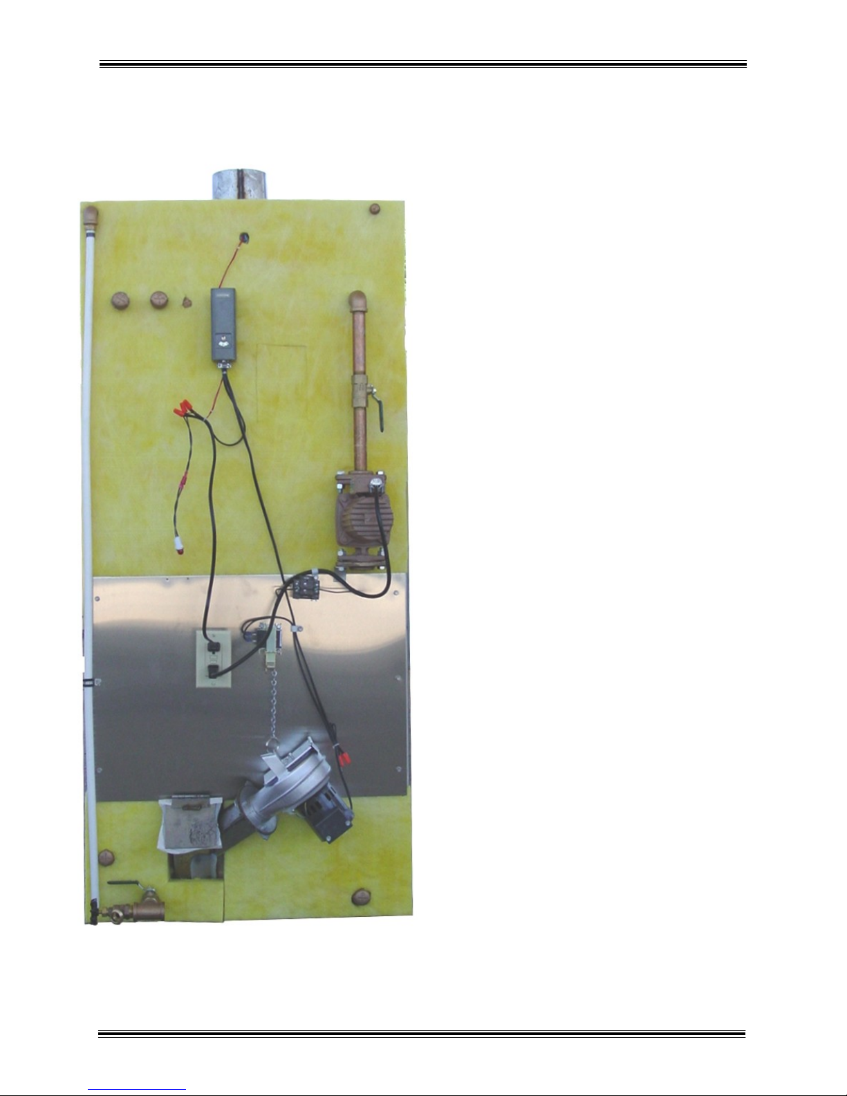
1-2 Heater Component Parts Model C3
29
27
26
25
24
23
21
20
19
18
17
16
15
14
13
13
12
11
11
28
22
10
9
8
7
7
7
7
6
5
4
3
2
1
Part No. Description
1 600.10 1/2” Brass Elbow
2 810.00 1/2” Overflow Pipe
3 1100.28 Low Water Switch
4 602.16 3/4” Brass Tee
5 603.40 3/4” x Close Brass Nipple
6 600.30 3/4” Brass Elbow
7 604.32 3/4” Brass Cap
8 604.16 1/2” Brass Cap
9 2000.48 1/2” Well Fitting
10 2000.08 Honeywell Aquastat
11 603.32 3/4” x 6” Brass Nipple
12 607.12 3/4” Brass Ball Valve
13 502.60 3/4” SS flange
14 502.50 Taco 009 SS Circulator
15 2004.40 Wire Connectors
16 1100.30 Low Water Light
17 2000.52 Honeywell Relay
18 2001.05 Damper Solenoid
19 2004.00 GFCI Receptacle
20 2004.16 Receptacle box 2 1/8” deep
21 3200.12 Jack Chain
22 3200.16 Key Ring
23 2002.16 100 CFM Blower / Lid
24 2004.28 Plastic Romex Connector
25 607.42 3/4” Boiler Drain
26 2004.04 3’ 3 Wire Power Cord
27 2004.08 8’ 2 Wire Power Cord
28 2004.52 Electrical Mounting Panel
29 604.00 1/4” Brass Cap

HARDY MANUFACTURING CO., INC (MODEL C3 & C5) PAGE 4
1-3 Heater Component Parts Model C5
Part No. Description
1 600.10 1/2” Brass Elbow
2 810.00 1/2” Overflow Pipe
3 1100.28 Low Water Switch
4 602.16 3/4” Brass Tee
5 603.40 3/4” x Close Brass Nipple
6 600.30 3/4” Brass Elbow
7 604.32 3/4” Brass Cap
8 604.16 1/2” Brass Cap
9 2000.48 1/2” Well Fitting
10 2000.08 Honeywell Aquastat
11 603.32 3/4” x 6” Brass Nipple
12 607.12 3/4” Brass Ball Valve
13 502.60 3/4” SS flange
14 502.50 Taco 009 SS Circulator
15 2004.40 Wire Connectors
16 1100.30 Low Water Light
17 2000.52 Honeywell Relay
18 2001.05 Damper Solenoid
19 2004.00 GFCI Receptacle
20 2004.16 Receptacle box 2 1/8” deep
21 3200.12 Jack Chain
22 3200.16 Key Ring
23 2002.16 100 CFM Blower / Lid
24 2004.28 Plastic Romex Connector
25 607.42 3/4” Boiler Drain
26 2004.04 3’ 3 Wire Power Cord
27 2004.08 8’ 2 Wire Power Cord
28 2004.52 Electrical Mounting Panel
29 604.00 1/4” Brass Cap
29
27
26
25
24
23
21
20
19 18
17
16
15
14
13
13
12
11
11
28
22
10
9
8
7
7
7
7
6
5
3
2
1
12
4

HARDY MANUFACTURING CO., INC (MODEL C3 & C5) PAGE 5
SECTION II
INSTALLATION OF HEATER
2-1 Location of Heater
The Hardy Heater is designed to be positioned outside the building to be heated. The
unit must be located a minimum of 10 feet from the building. The unit should be
installed upon a concrete pad. There are two typical options that we recommend.
Option 1 has the unit installed on concrete pad with the rear of the water tank flush with
end of the pad. We recommend the pad to be 48” wide and 53” long minimum. If you
add extra length it will allow ample concrete in front of the heater for loading fuel and
removing ashes. The space between the rear of the unit and the outside cover will
allow a 4” watertight pipe or other means to insulate the plumbing and electrical lines to
run directly into the ground. The outside cover can be removed by lifting it off the water
tank on all four corners. This will allow you easy access for the connection of the
plumbing and electrical lines.
Please see the illustration below for details.
58.000
48.000 20.000
14.000
6.000
Option 1

HARDY MANUFACTURING CO., INC (MODEL C3 & C5) PAGE 6
2-1 Location of Heater
Option 2 illustrates the unit installed on a concrete pad with cut out in the pad for
plumbing and electrical connects to run through. We recommend this pad to be 48”
wide by 60” minimum long. If you add extra length it will allow ample concrete in front
of the heater for loading fuel and removing the ashes. The 4” watertight pipe or other
means to insulate plumbing that runs underground exits through this cut out to allow
connections to the unit. The unit sits on the pad with the rear of the water tank flush or
even with the front side of the cutout. The outside cover of the heater can be removed
by lifting it from the water tank on all four corners. This will allow you easy access for
the plumbing and electrical connections.
Please see the Illustration below for details.
Option 2
60.000
48.000
4.000
6.000
20.000
14.000
This manual suits for next models
1
Table of contents
Other Hardy Heater manuals


Popular Heater manuals by other brands

RollSeal
RollSeal 100 owner's manual

STIEBEL ELTRON
STIEBEL ELTRON CNS 125 S Operation and installation instructions

Rointe
Rointe Sygma SRI0330RAD2 instruction manual

Maxkon
Maxkon STAR 2000 Installation & operating instructions

MILL
MILL CUS1800MECWA Assembly and instruction manual

Hiton
Hiton HP-115 user manual

L.B. White
L.B. White Pilot Light Ignition Installation and service guide

Schwank
Schwank STS-JZ Installation & owner's manual

Wacker Neuson
Wacker Neuson HDR155 Operator's manual

INTELLI HEAT
INTELLI HEAT MySense iSense Brief guide

Supplies4Heat
Supplies4Heat BEAUFORT Slim Fitting instructions

Dantherm
Dantherm MASTER CF 75 User and maintenance manual


