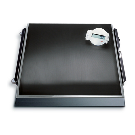
Hardy HIPS series User manual

HIPS SERIES
PLATFORM SCALES
OPERATION AND INSTALLATION
MANUAL
Corporate Headquarters
3860 Calle Fortunada
San Diego, CA 92123-1825
Phone: (858) 278-2900
FAX: (858) 278-6700
Web-Site: http://www.hardyinst.com
Hardy Instruments Document Number: 0596-0191 Rev B-1
Copyright November 1999 Hardy Instruments, Inc. All Rights Reserved. Printed in the U.S.A. (941028)

CAUTION: UNPACK WITH CARE
WHEN UNPACKING, DO NOT DISCARD THE PACK-
ING CASE OR ANY PACKING MATERIAL, UNTIL THE
CONTENTS OF THE PACKING CASE ARE
INSPECTED AND CAREFULLY COMPARED WITH
THE SHIPPING DOCUMENTS.
IF ANYTHING IS UNSATISFACTORY, PLEASE
NOTIFY HARDY INSTRUMENTS IMMEDIATELY BY
CALLING, FAXING OR E-MAILING TO:
Customer Support Department
HARDY INSTRUMENTS, INC.
3860 Calle Fortunada
San Diego, California 92123-1825
Phone: (800) 821-5831
(858) 278-2900
FAX: (858) 278-6700
E-mail: [email protected]
Web Address: www.hardyinst.com
A RETURN AUTHORIZATION NUMBER IS REQUIRED
BEFORE RETURNING ANY DAMAGED PRODUCT.
CALL THE CUSTOMER SUPPORT DEPARTMENT TO
GET THE NUMBER. YOUR COMPANY NAME,
ADDRESS, TELEPHONE NUMBER, SERIAL NUMBER
OF THE UNIT AND A BRIEF DESCRIPTION OF THE
PROBLEM SHOULD BE READY WHEN CALLING.
IN CASE OF DAMAGE DUE TO SHIPPING, NOTIFY
THE DELIVERING CARRIER IMMEDIATELY FOR AN
INSPECTION.

HIPS SERIES PLATFORM SCALES
i
Table of Contents
Table of Contents- - - - - - - - - - - - - - - - - - - - - - - - - - - i
Introduction - - - - - - - - - - - - - - - - - - - - - - - - - - - - -1-1
Description - - - - - - - - - - - - - - - - - - - - - - - - - - - - - -1-1
The Stainless Steel Platform Cover - - - - - - - - - - - - - - - -1-1
Upper Frame Assembly - - - - - - - - - - - - - - - - - - - - -1-1
Single Point Load Cell - - - - - - - - - - - - - - - - - - - - - -1-1
Lower Frame Assembly - - - - - - - - - - - - - - - - - - - - -1-2
Preassembly Precautions - - - - - - - - - - - - - - - - - - - - - -1-2
Unpacking and Assembly - - - - - - - - - - - - - - - - - - - - - -1-2
Leveling the Scale - - - - - - - - - - - - - - - - - - - - - - - - - -1-3
Electrical Connections - - - - - - - - - - - - - - - - - - - - - - - -1-3
Calibration - - - - - - - - - - - - - - - - - - - - - - - - - - - - - -1-3
C2 Second Generation Calibration - - - - - - - - - - - - - - - -1-4
Test Weight Calibration (Hard Cal) - - - - - - - - - - - - - - - -1-4
Material Substitution - - - - - - - - - - - - - - - - - - - - - - -1-4
Electrical Specifications - - - - - - - - - - - - - - - - - - - - - - -1-4
Mechanical Dimensions - - - - - - - - - - - - - - - - - - - - - - -1-5
Capacities - - - - - - - - - - - - - - - - - - - - - - - - - - - - - -1-8
Model Numbers - - - - - - - - - - - - - - - - - - - - - - - - - - -1-9
Troubleshooting - - - - - - - - - - - - - - - - - - - - - - - - - - -1-9
Scale does not respond when weight is applied - - - - - - - - - -1-9
Scale indication is not linear - - - - - - - - - - - - - - - - - - -1-9
Scale reads backwards - - - - - - - - - - - - - - - - - - - - -1-10
Scale reading drifts or is erratic - - - - - - - - - - - - - - - - - -1-10
Service and Repair - - - - - - - - - - - - - - - - - - - - - - - - - -1-10

HIPS SERIES PLATFORM SCALES
1-1
Introduction Congratulations on your purchase of a Hardy Instru-
ments HIPS Series platform scale. The Hardy Plat-
form Scales are designed for table top or floor
applications requiring high accuracy and reliability.
The covers are all stainless steel for durability. The
bases have no bearings, bubble levels, or moving
parts that can be damaged or wear out. The active ele-
ment of the scale is a precision strain gauge load sen-
sor.
Each platform is certified for use in a C2®Second
Generation Calibration System.
Description The basic HIPS platform scale consists of four major
components:
1. Stainless Steel Platform Cover.
2. Upper Frame Assembly
3. Single Point Load Cell
4. Lower Frame Assembly
The Stainless
Steel Platform
Cover
The platform cover is a single piece constructed of
series 300 Stainless Steel. The cover provides a
weighing surface and offers protection to the load
cell. Access to the upper frame, load cell and lower
frame is gained by lifting up on the cover.
Upper Frame
Assembly The upper frame is bolted directly to the load cell and
serves as support for the platform cover. In the HI
1212PS/S and the Hi 1318PS/S the upper frame is
made of cast aluminum. The HI 1842PS and HI
2424PS upper frame is all stainless steel. They all
have rubber load pads and a shock load adjustment.
Single Point Load
Cell The HIPS Series Platform Scales have potted alumi-
num load cells with a unique humidity resistant pro-
tective which assures long term stability even under
harsh environment and extreme temperatures. All
HIPSS series scales have potted stainless steel load
cells. Each cell has a six conductor cable, ten (10) feet

HIPS SERIES PLATFORM SCALES
1-2
long with C2®on its end. The output of each cell is
2mV/V with 5 to 15 volts DC excitation.
Lower Frame
Assembly The lower frame assembly is also bolted directly to
the load cell and serves as support and protection. It
comes equipped with four leveling feet, a shock load
set screw and corner overload adjustments. The cor-
ner overload adjustments have been factory set to bot-
tom out at approximately 75% of the scale capacity.
DO NOT change this adjustment. As in the upper
frame assembly the HI 1212PS/S and the HI 1318PS/
S lower frame is made of cast aluminum. The HI
1824PS and HI 2424PS lower frame is all stainless
steel.
Preassembly
Precautions Do not store or operate the scale out of its specified
temperature range.
Do not store other equipment on the scale when it is
not in use or in storage.
Do not allow a build-up of debris on, around or under
the scale.
Do not set the scale in water or allow water to settle
around the scale. Provide Proper drainage.
Do not let moisture get on or into any of the electrical
interconnections.
Do not allow static or other electrical discharges
through the scale.
Do not try to adjust the shock or over load stops.
Do not try to remove the load cell or adjust the allen
set screws above or below the load cell.
Unpacking and
Assembly The HIPS Series scales are shipped fully assembled
and only require adjustment of the leveling feet. If
there is any damage to the shipping container or to the
scale save, all the packaging material and file a report
with the shipper.

HIPS SERIES PLATFORM SCALES
1-3
Make sure each corner of the upper frame assembly
has a rubber boot or strip and that there is a rubber
strip in the center for the HI 1212 and Hi 1318 scales.
For the HI 1824 and HI 2424, make sure there are rub-
ber strips in each corner, down the center and at the
center of each 24 inch length of the upper frame.
Leveling the Scale To level the scale, loosen the foot lock nut on the
lower frame assembly and turn the foot clockwise to
lower the scale corner, or counter clockwise to raise
it. Tighten the lock nut when no wobble of the scale is
detected.
Electrical Connections Make sure the cable is not pinched and is clear of the
feet, cover, and overload stops. The platform requires
a recommended DC or AC excitation voltage of 5
volts with a maximum of 15 volts. Wire the platform
load cell cable to an instrument or indicator following
the color code label found on the upper frame or as
follows:
+ Excitation Green
+ Sense Blue
+ Signal Red
+ C2 Cal Gray
- Signal White
- Sense Brown
- Excitation Black
- C2 Cal Violet
WARNING USE CAUTION WHEN WIRING. MAKE SURE
TO DISCONNECT ALL POWER TO THE
SCALE. FAILURE TO REMOVE POWER CAN
RESULT IN SCALE OR INSTRUMENT DAM-
AGE, DEGRADATION OF PERFORMANCE OR
PERSONAL INJURY
Calibration To calibrate the platform, make sure the platform is
wired correctly to the weighing instrument/indicator.
Refer to the weighing instrument/indicator manual for
calibration instructions.

HIPS SERIES PLATFORM SCALES
1-4
C2 Second
Generation
Calibration
C2 electronically calibrates a scale system without the
need for test weights. If you are using a Hardy Instru-
ments HI 2151/20WC, HI 2151/30WC, HI 2160RC
controller or HI 1746-WS, Hardy HI 1771-WS weigh
module, all that’s required is to enter a reference
point. Refer to the instrument or module manual for
instructions.
Test Weight
Calibration (Hard
Cal)
This is the traditional means of calibration requiring
certified class F test weights equal to a minimum of
80% of the rated scale capacity. Additionally three
weights between 10% and 100% of the scale capacity
should be available to check the mid-range. Several
low capacity weights equivalent to one or two instru-
ment divisions are necessary to check the system sen-
sitivity.
Material
Substitution When certified test weights are not available you can
use an accurately weighed material to calibrate the
system. In this method, a material is weighed on a
secondary, calibrated scale and delivered to the site of
the scale to be calibrated. The secondary calibrated
scale should be of the same accuracy or greater and
have a capacity approximately equal to the scale
being calibrated.
Electrical
Specifications Rated Output 2mV/V +- 10%
NOTE: All accuracy specifications are maintained when
150% of nominal load is applied for 3mV/V output.
Excitation:
Recommended 5-10 Volts AC or DC
Maximum 15 Volts AC or DC
NOTE: 20 volts maximum on the 1824 & 2424 models.
Total Error 0.02% of rated output
Maximum Overload
At the Center

HIPS SERIES PLATFORM SCALES
1-5
Loading Point 200% of the rated
capacity
Temperature Range
Safe -30 to +70 Degrees C
Compensated -10 to +50 Degrees C
Temperature Effect
On Output 0.0014% of load/oC
On Zero 0.003% of rated
output/oC 0.006% of
rated output/oC for the
HI 1318PSS-C400
Cable 10 feet, 6 conductor,
Polyurethane Jacket,
Floating Shield
Mechanical
Dimensions The following dimensions are for reference only

Wire Color Signal
Gray + C2
Violet - C2
Green + EXC
Blue + SENSE
Red + SIG
Black - EXC
Brown - SENSE
White - SIG
Inches
(mm) HI 1212PS
HI 1212PSS HI 1318PS
HI 1318PSS HI 1824PS HI 2424PS
A12 (305) 13.75 (349) 18 (457) 24 (610)
B12 (305) 18.55 (471) 24 610) 24 (610)
C3.75 (95) 3.75 (95) 4.5 (114) 4.5 (114)
HIPS SERIES PLATFORM SCALES
1-6

HIPS SERIES PLATFORM SCALES
1-7
Base for HI 1212PS/PSS and HI 1318 PS/PSS With cover removed.
Base for HI 1824PS and HI 2424PS with cover removed.

HIPS SERIES PLATFORM SCALES
1-8
Capacities
LBS
(KGS) HI 1212
PS HI 1212
PSS HI 1318
PS HI 1318
PSS HI 1824
PS HI 2424
PS
10 (4.5) X
25 (12.2) X X X X
50 (24) X X X X X
75 (35) X
100 (45.3) X X X X X
125 (60) X
150 (68.5) X X X X
175 (80) X X
200 (93) X X X X
275 (127) X
300 (136) X
400 (181.4) X X X
500 (292) X X
600 (277) X X
1000 (472) X X
1300 (602) X X

HIPS SERIES PLATFORM SCALES
1-9
Model Numbers
Troubleshooting
Scale does not
respond when
weight is applied
Step 1. Make sure the scale is wired correctly to
the instrument and there are no breaks in
the wiring.
Step 2. Lift off the lid and see if there is packing
material or debris wedged under the scale.
Step 3. Check to see that the corner stops are not
touching the top frame. On the 1824 or
2424 insure the shock bolt is not touching
the lower frame.
Step 4. Verify that the Instrument is operating cor-
rectly.
Scale indication is
not linear Step 1. Check the instrument for proper calibra-
tion.
Step 2. Lift off the lid and see if there is packing
material or debris wedged under the scale.

HIPS SERIES PLATFORM SCALES
1-10
Step 3. Check that the corner stops are not touch-
ing the top frame. On the 1824 or 2424
insure the shock bolt is not touching the
lower frame.
Step 4. Make sure all electrical connections are
tight with no corrosion and that there has
not been an ingress of moisture to the sys-
tem.
Scale reads
backwards Check for correct wiring to the instrument. The +-
signal or excitation wires may be reversed.
Scale reading
drifts or is erratic Step 1. Make sure all electrical connections are
tight with no corrosion and that there has
not been an ingress of moisture to the sys-
tem.
Step 2. Verify that the instrument is operating
properly.
Step 3. Make sure there are no high voltage wires
close to the scale’s load sensor.
Step 4. Check that the scale and instrument are
properly grounded.
Step 5. If high static electricity is present a ground
strap should be added from the platform
cover to the lower frame assembly and to
earth ground.
Service and Repair For Service and Repairs, contact your local Hardy
Representative.
Before returning any product to Hardy Instruments
Inc., please contact the Customer Support Department
for a return authorization number. Please have the
scale model number and serial number and a brief
description of the problem ready when you call.
Customer Support Department
Hardy Instruments, Inc.
3860 Calle Fortunada
San Diego, California 92123-1825
Table of contents


