Harmony HB 46 ADSP User manual

DSP/AMPLIFIER
HB 46 ADSP
HB 48 ADSP
Quick Guide
Before operating the unit, please read this manual throughly
and retain it for future reference.
Any updates are available on harmonycar.it

Table of Contents
Before you start installation 4
All wire is not created equal 4
Plannin your power connections 5
More words about Power and Ground 6
Wire size 6
Mountin your unit 7
Remote Control 7
Control Panel (RCA, USB) 8
Control Panel (Power, Hi-Lev, Rem, BT) 9
PC Control Pro ram 10
Main Screen 11
File Menu 12
I/O Matrix 12
System Phasin 12
Mobile Control Pro ram (APP) 14
Main Screen 14
Channel Setup 15
Equalizer 15
Crossover 16
System 16
I/O Matrix 17
Music Player 17
Technical Specifications 18
32

Before you start nstallat on
We recommend that a fuse or circuit breaker be placed within 18" of the battery.
Althou h you will add a fuse or fuse block near the amplifier it is still a possibility that a
pinched power wire between the component fuse and the battery could result in a short,
or even a fire. The protection device should be placed where it can be accessed easily
and all wirin should be routed safely and correctly accordin to the followin uidelines:
• Do not run wirin close to hot or spinnin objects.
• Use wire rommets when routin wire throu h the firewall or any other metal panels
• Make sure that the potential for pinched wirin is avoided by routin all wires away
from movin objects, includin brake, as and clutch pedals, etc.
When connectin our amplifiers to pre-wired stock speakers, care must be taken that there
are no common connections between left and ri ht speaker wires, i.e. two or more speakers
usin the same round connection (very common in pre-85 cars), as this will cause the
amplifier to o into immediate protection or may cause dama e to the amplifier. Output
connections are not common chassis round. Please follow the hookup instructions in
this owner's manual. Any questions should be directed to your local dealer.
All w re s not created equal
It is easy to think of wire as just wire but the fact is there are major differences between
the types of wires bein offered today. The price of copper has one up quite a bit lately,
but you will notice that you can still buy heavy primary wire at very reasonable prices.
How can this be? Simple... That lower price wire is not all copper, it is CCA wire.
CCA stands for Copper Clad, Aluminum. That means it is aluminum wire with a thin coatin
of copper around the outside of the wire. Does it conduct electrical current like copper?
Absolutely not. If the wire does not say OFC Copper wire or Solid Copper wire do not use it.
Two thin s can and likely will happen:
• Because CCA wire can not conduct DC electrical current like copper wire can, your amp
will not et the current it needs to produce its rated power. That means you et less
power and more distortion. It also taxes the amplifier that is tryin to make its power,
shortenin the life of the amp.
• CCA wire corrodes quickly and causes terminals that used to be ti ht to become
loose. This causes arcin when electrons to fly around all the open space lookin for
more copper. This causes heat that dama es connections and can even eventually
melt the terminal blocks on your amplifier.
In short: While CCA wire is excellent for hi h frequency AC current (like tweeter voice
coils), it is absolutely bad for hi h current 12V DC like power and round for a car audio
amplifier. We have seen CCA wire become a major cause of amplifier failures as buyers
are offered CCA as a low cost alternative to pure copper wire. So always look at the
description of the contents of wire that you purchase. When someone offers to save you
some money with CCA wire just say "No, thank you". Protect your investment with real
copper wire.
Plann ng your power connect ons
The power end plate has the main 12-volt power input, the 12-volt turn-on wire, and the
main Ground connection.
• The 12-volt power input must be connected the vehicle battery's positive (+)
terminal, and a main system fuse should be placed close to the battery.
• The Ground connection must be securely attached to bare metal at the vehicle
frame, or other heavy chassis component with a direct connection to the frame.
Note: Seat bolts and seat belt bolts are NOT good ground po nts
• The REM In input can be connected to the head unit turn-on output wire.
If none is available it can be connected to an accessory (ACC) terminal. You should
avoid usin any i nition-on (IGN) wire, as they can be noisy.
4 5

6 7
More words about Power and Ground
The second most common cause of under performin amplifiers is insufficient power
current or a poor power connection. The most common cause of under performin
amplifiers is insufficient round current or a bad round connection.
12-volt current: Battery power works only if it travels in a complete circuit from the battery
positive terminal to the battery ne ative terminal. Main power input, of course, is attached
to the battery positive terminal. Ground current is returned to the battery throu h the
chassis to the point where the battery is rounded.
The current available for your amplifier to use to produce power will be restricted by the
smallest au e of wire in the circuit and by the weakest physical connection in the circuit.
W re S ze
It's often surprisin how many people will obsess about si nal wire but routinely provide
the amplifier with only a fraction of the current it needs to do its job. The most common
wire au e used in car audio is 10- au e, and the most common location for amplifiers
is in the trunk. That will only be ood for about 100 watts (See the chart).
4 ft 7 ft 10 ft 13 ft 16 ft 19 ft 22 ft 28 ft
0-20 amps 14 12 12 10 10 888
20-35 amps 12 10 886664
35-50 amps 10 8866444
50-60 amps 88644442
65-85 amps 66442220
85 -105 amps 66422220
105-125 amps 44422000
125-150 amps 22220000
Let's look at a fairly small system. If you use a 50 watt/ch amp (25 amps) for the hi hs
and a 100 watt/ch amp (40 amps) for the woofers, you need at least a 4- au e and
maybe a 2-Gua e wire to provide 65 amps at the trunk. Use the Wire Sizin Chart. Add
up the fuse values on the amplifier(s) then choose the proper size wire based on the dis-
tance from the car battery to the amplifier location. Always use the same au e wire for
the main round as you do for the main power. Always make your round as short as
possible and secure it to a clean solid surface, preferably the vehicle frame.
Length of Run
Mount ng your un t
Mountin your unit is easy. Just keep in mind a few uidelines:
• The unit can be mounted in any direction, on wood, metal, or carpet but not upside
down as heat rises and will build up if it is mounted upside down.
• The metal chassis of the amp can be rounded or left isolated.
• The amplifier requires adequate ventilation. Creatin power creates heat, and
coolin requires air. Position the amplifier with sufficient surroundin area for air
supply and keep the end plates clear for future access.
• Keep the unit out of the en ine compartment or other locations that may cause
excessive heat or moisture.
• Do not mount the unit to a subwoofer box or other place that may have excessive
vibration.
Remote Control (opt onal)
Here the remote controls.
Press the knob to switch between:
• VOL. Rotate the knob
to increase/decrease
the main volume.
• S.VOL. Rotate the knob
to increase/decrease
the subwoofer volume.
• PRESET. Rotate to switch
between presets, then
press to enter. Press and hold for 3 sec. to o back to volume mode.
• SOURCE. Rotate to switch between available input sources.
PLAYER Mode. Connect a USB device to the external BT module and plu -in into the
dedicated port. Press the knob to select SOURCE then rotate the knob to select USB.
Press to confirm, then rotate the knob to o to the previous or the next son . Press and
hold to o back to volume mode.

Control Panel (RCA, USB)
Both the units share the same panel, except the RCA outputs.
1 - USB Port, to connect your PC for DSP calibration and updates.
2 - 6- Channels (HB 46 ADSP), 8-Channels (HB 48 ADSP) RCA Outputs.
3 - 2-Channels RCA Inputs.
8 9
1
HB 48 ADSP HB 46 ADSP
2 3
Control Panel (Power, H -Lev, REM, BT)
Both the units share the same panel.
1 - Hi-Level Speaker Inputs and Outputs, Power/Ground/Rem Connections.
Use only the ori inal harness provided. Here a detail of the connector functions.
2 - Hi-Level/Rem In Switch.
3 - Remote Control Port.
4 - Bluetooth Port for external BT/Player module.
1 2 3 4

10 11
PC Control Program
The Control Pro ram requires no installation. Just download the file from the Harmony
website an put it on your desktop. You should check back on the site re ularly to assure
you have the most up-to-date version of the software. Below is the layout of the main
screen (6-Ch./15-bands EQ for the HB 46 ADSP model and 8-Ch./31-bands EQ for the
HB 48 ADSP model).
Ma n Screen
Both the units share the same GUI, but the HB 46 ADSP has a 6-Channels DSP with a
15-bands EQ, while the HB 48 ADSP has a 8-Channels DSP with a 31-bands EQ.
1 - At the very top of the GUI there is the F le Menu (Pa . 14). The Preset button is
where you will save setups to memory presets and load setups from those saved.
Option let you choose Lan ua e and other tools like BT/USB volume. The Mix
button opens the I/O Matrix screen, where you can manually determine which
inputs will be used for each output and how much of each input the output will
receive. Encrypt is where you mana e your password.
2 - Here you choose the Input you will use while tunin . You can choose AUX which
can be an aftermarket head unit, or a factory head unit usin the HI-LEV option.
You also have USB and BT (Bluetooth) input if you add the optional module.
3 - Connection status.
4- H gh-Pass and Low-Pass F lter for each channel. You can type in the frequencies
and choose crossover style and slope or turn the crossovers off, if you do not want
them for some channels. Always check the speaker makers recommendations for
crossovers before you make the crossover decisions.
5 - EQ area. Here are 15-bands (HB 46 ADSP) or 31-bands (HB 48 ADSP) of
parametric equalization for each output channel and you can vary Frequency, Gain,
and Q (the shape of the adjustment) for each band. Frequency: Each band is
numbered. You can simply click onto a band button and dra it to where you want
it. When you click onto a band there is a “Heads-up display” of the Frequency, Gain,
and Q of the band.
6 - Here you find the master level control.
7- The Output Channels section is for Speaker Assi nment, Delay, adjustin Levels and
checkin Polarity to be sure all speakers are in phase with each other. There are a
number of systems for checkin System Phase. If the systems speakers are not
all in phase there will be issues you can not fix by tunin . You can see the section
on System Phasin (Pa . 12) to see one method of Phase checkin . The MUTE
buttons allow you to turn off any speakers that you do not want to hear while you
are tunin other speakers. The purpose of Delay is to make every speaker the
same distance from you, so you are in the middle.
8 - Here you choose between GEQ (Graph c) and PEQ (Parametr c) equalizers, or
Reset EQ, if you want to reset channels to default positions with no equalization.
9 - Here you Reset, Link or Lock Output Channels.
HB 48 ADSP Ma n Screen HB 46 ADSP Ma n Screen
1
2 3
4 5
6 7 8
9

12 13
F le Menu
At the very top of the GUI there is the File Menu. The Preset button is where you will save
setups to memory presets and load setups from those saved. Here you can also save
setups into your PC. Opt on button let you choose between Lan ua es, Noise Reduction,
Reset function, Input volume, and informations about your device and software. MIX will
open the I/O Matrix screen (see below). With Encrypt you can mana e your Password.
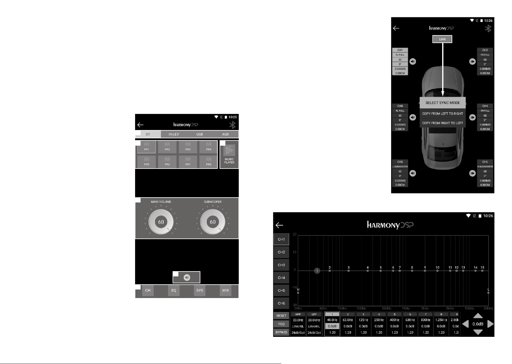
I/O Matr x
With the Mixin Set, you can manually determine which inputs will be used for each output
(processin channel) and how much of each input the output will receive. The inputs are
listed down the left side and the output channels are listed across the bottom.
System Phas ng
Before equalization you should assure that all speakers are in phase as a system at the
listenin position. All speakers need to have the same polarity so they move the same
direction at the same time. If they are not, you will not be able to et a proper tune.
There are a number of methods for doin this. We offer one.
Tweeters (A): Mute all speakers except the tweeters and play a hi h female vocal solist.
You should hear the voice at a sin le point near upper middle of the windshield. If the
speakers are out of phase the voice will not be localized but will seem to come from
everywhere. To test, usin the Phase buttons, chan e the phase of the ri ht speaker and
listen for the difference. Do this a couple of times as needed. The position that puts the
voice in a small sin le location on the window is the correct phase.
Tweeters (B): Note where the Tweeter center is located. It should be just sli htly above
and to the left of the center of the windshield (for left hand drive cars). If it is off to the
opposite side of center or too far to the left, and if you have measured correctly, then you
have a ain difference and you can correct by a sli ht level adjustment reduce the ri ht
tweeter to brin it left or reduce the left channel to take it ri ht. No more that 1dB or
2dB. Now the tweeters are set. From here on out you cannot chan e the levels or phase
of either tweeter.
M ds, M d-Woofers, and Subs: Now mute the tweeters and un-mute the midran es.
The process is the same for each pair of speakers. The sound should come from a sin le
focused point near the center of the windshield. For midran es and lar er drivers, you
want to use a deeper male vocal. The lar er drivers are much easier to tell the differences
between in-phase and out of phase. Also, with the lar er speakers you will hear a dramatic
reduction of bass if the speakers are out of phase. So, for midran e and lar er speakers
you will look for a focused sound source in the windshield with stron er bass.
NOTE: Once each channel pa r s adjusted, they cannot be separated. Any change of phase must be
done by the pa r.
Phas ng the pa rs: A ain, listenin to a sin le vocalist. Mute all channels a ain except
the tweeters. Then brin in the midran es. If these pairs are in proper phase the sound
should be near center in the upper part of the windshield. If they are not in phase the
sound will be pulled down lower. You can reverse the phase of BOTH mids now and
listen for the difference in the sound location. Choose the phase position that puts the
sound hi h near the center.
Once you have these phased you can brin in the mid-bass with the same process. A ain,
the focus should be hi h in the dash. If the mid-bass is out of phase with the tweeters
and mids then they will pull the sound down toward the floor.
Woofers or Subs: There will be bass! You have phased the woofers, so we know there
will be bass. What you need to listen for here is location, and mid-bass (somethin with
kick drums is ideal). Proper woofer phasin will work with the mid-bass drivers to ive
ood solid, crisp mid-bass. Out of phase will result in a soft, low-impact mid-bass. Bass
out of phase with the mid-bass will also be more located in the back of the vehicle while a
properly phased bass will blend better into the front soundsta e.

14 15
Mob le Control Program (APP)
The HB 46 ADSP and HB 48 ADSP apps are identical, except for the number of channels
and EQ bands, dependin on the models, (6-Ch./15-bands EQ for the HB 46 ADSP model
and 8-Ch./31-bands EQ for the HB 48 ADSP model). The oal is to have a control system
that made sense in a smaller platform but would allow the user to do everythin necessary
for a complete setup and tune with a smartphone or tablet.
Turn on your unit and connect the ext. BT module. It will enter into pairin mode with blue
li ht flash alternately. Open the Bluetooth of your smart device and search the DSP for
pairin . Red BT icon means not connected.
Ma n Screen
1 - In the main screen you will find the
Input Source menu where you can
choose BT, HI-LEV, USB and AUX.
2 - Here you find 8 Presets (saved into
your device) to choose from.
3 - Here you open the Music Player.
4 - Main and Subwoofer Volume.
5 - System MUTE.
6 - The advanced menu with Channels,
EQ, System and Mixin buttons.
1
2 3
4
5
6
Channels Setup
Click on CH button in the main screen
and you will have the Channel setup
screen. Choose from 1 to 6 (model HB
46 ADSP) or from 1 to 8 (model HB 48
ADSP) to setup:
• Channel Assi nment
• Gain
• Phase
• Delay (in MS and CM)
You can also mute each channel with the
individual speaker icon. LINK button let you
link channels between them.
Equal zer
Click on EQ button in the main screen
and you will have the EQ main pa e
(6-Ch./15-bands EQ for the HB 46 ADSP
model and 8-Ch./31-bands EQ for the
HB 48 ADSP model).

16 17
Crossover
Hi h-Pass and Low-Pass Filter for each
channel. You can type in the frequencies
and choose crossover style and slope or
turn the crossovers off, if you do not want
them for some channels. Always check
the speaker makers recommendations
for crossovers before you make the
crossover decisions.
System
Click on SYS button in the main screen
and you will have the System screen with
the followin functions.
• USB/BT Levels.
• Mana e Presets
• Noise Reduction
• Resume Factory Settin / Password
• Device and Software informations
I/O Matr x
Click on MIX button in the main screen
to enter the I/O Matrix.
You can manually determine which inputs
(USB-L/R, Di ital-L/R, BT-L/R) will be
used for each output (processin channel)
and how much of each input the output
will receive.
Mus c Player
Connect a USB device to the external BT
module and plu -in into the dedicated port.
Click on USB button on input source
menu, then click on Music Player button
in the main screen to enter the Player.
Be sure the USB device contains audio
files in the supported format (MP2/4,
WMA, APE, FLAC, AAC, M4A,WAV, AIF,
AIFC). From the App it is possible to
access the folders and the contained
audio files.
HBT1

18 19
Technical Specifications
Main Features
DSP Channe s 6 (HB 46 ADSP) - 8 (HB 48 ADSP)
High Leve Inputs 4-Channe s
RCA Inputs 2-Channe s
RCA Outputs 6-Channe s (HB 46 ADSP) - 8-Channe s (HB 48 ADSP)
Amp ifier Power 4 x 70W (Max)
P ug & P ay Ready Yes
BT 5.1 Streaming Yes
Music P ayer Yes (APP)
Audio Format MP2/4, WMA, APE, FLAC, AAC, M4A,WAV, AIF, AIFC
DSP Too s PC and APP
DSP Features
DSP Equa izer 15-Bands (HB 46 ADSP) - 31-Bands (HB 48 ADSP)
Input Choice: AUX, BT, HI-LEV, USB
I/O Mixing Matrix Yes
Crossover High-Pass - Low-Pass Fi ter
Crossover Type Butterworth, Besse , Linkwitz–Ri ey
Crossover S ope 6-12-18-24-30-36-42-48 dB/Oct.
De ay 0.00-20.00 ms, 0.00-692.00 cm, 0.00-273.00 in.
Technicals
Active Range > 110dB
S/N Ratio > 100dB
THD < 0.05%
Samp ing Rate 48KHz/24Bit
Frequency Response 20Hz - 20KHz
Amp ifier Power 4 x 35W (Norma ), 4 x 70W (Max)
Input Impedance 20 KOhm (Low), 240 Ohm (High)
Signa I/O Range RCA Input 6Vpp, RCA Output 9Vpp, High-Lev. 26Vpp
Power Supp y DC 9V-16V
Power Consumption < 0.1W
Dimensions: 135 (159) x 115 x 45.5 mm (HB 46 ADSP)
160 (184) x 115 x 45.5 mm (HB 48 ADSP)
81.8 x 36.8 mm (optiona Remote)

HARMONY is a B and of APEX G oup
APEX Eu ope s l
Via della Meccanica 14 - 04011 Ap ilia LT - ITALY
ha monyca .it / man hb 46.48 adsp v.1.0
This manual suits for next models
1
Table of contents